Table of Contents
Advertisement
Quick Links
Advertisement
Table of Contents

Related Manuals for EXFO ETS-1000G


Summary of Contents for EXFO ETS-1000G
- Page 1 User Guide ETS-1000G 10 Gigabit Ethernet Analyzer...
-
Page 2: Copyright Information
Copyright Information Copyright Information Copyright © 2013 EXFO Inc. All rights reserved. No part of this publication may be reproduced, stored in a retrieval system or transmitted in any form, be it electronically, mechanically, or by any other means such as photocopying, recording or otherwise, without the prior written permission of EXFO Inc. -
Page 3: Table Of Contents
Contents Contents Copyright Information ......................ii Certification Information ...................... vii 1 Introducing the ETS-1000G ................1 Scope of use ...........................1 Conventions ..........................4 Supply Kit ..........................5 2 Safety Information ..................7 Laser Safety Warnings ......................7 Installation Instruction Warnings ....................8 3 Device Description ..................9 Front Panel ..........................9... - Page 4 16 Statistics ......................95 Summary statistics ........................95 Statistics of Frame Types .......................96 Statistics of Frame Sizes ......................97 Statistics for Layers .......................98 Statistics of Frame Errors ......................99 17 Saving test results and statistics .............101 18 Network Parameters .................103 19 Interface Parameters ................105 ETS-1000G...
- Page 5 26 Warranty ....................133 General Information ......................133 Liability ..........................134 Exclusions ...........................135 Certification ........................135 Service and Repairs ......................136 EXFO Service Centers Worldwide ..................137 A Specifications ..................... 139 Interfaces ..........................139 Testing ..........................139 General Features .........................141 Delivery options ........................142 10 Gigabit Ethernet Analyzer...
- Page 6 Test Sequences ........................148 Digits, Letters, and Characters ....................148 C Remote Control Commands ..............151 Remote control commands (a console terminal) ..............151 Remote control commands (TELNET). Configuration mode ..........162 D Ethernet Frame Structure ................171 E Glossary....................... 173 Index .......................181 ETS-1000G...
-
Page 7: Certification Information
Electronic test and measurement equipment is exempt from FCC part 15, subpart B compliance in the United States of America and from ICES-003 compliance in Canada. However, EXFO Inc. makes reasonable efforts to ensure compliance to the applicable standards. The limits set by these standards are designed to provide reasonable protection against harmful interference when the equipment is operated in a commercial environment. - Page 8 European Union Directive and Standards mentioned in the Declaration of Conformity. Laser Your instrument is a Class 1 laser product in compliance with standards IEC 60825-1 and 21 CFR 1040.10. Laser radiation may be encountered at the output port. viii ETS-1000G...
- Page 9 Tel.: +44 2380 246 800 Equipment Type/Environment: Test & Measurement / Basic Trade Name/Model No.: Ethernet Loopback Device / ETS-1000G Standard(s) to which Conformity is declared: EN 55022: 2006 Information technology equipment — Radio disturbance characteristics — Limits and methods of measurement...
-
Page 11: Introducing The Ets-1000G
Introducing the ETS-1000G The analyzer ETS-1000G (hereinafter referred to as the device, the tester) is designed for analyzing and performing diagnostic tests of equipment in the Ethernet networks. It supports all data transfer rates from 10 Mbps to 10 Gbps. - Page 12 Introducing the ETS-1000G Scope of use Key Features and Benefits Interfaces: 10G Ethernet: SFP+; 1G Ethernet: SFP (1000BaseX) / RJ-45 (10/100/1000BaseT); LAN 10/100 BASE-T; USB 1.1/2.0. ETS-1000G...
- Page 13 Setting up a loopback on the physical, data link, network and transport layers. Intelligent device search mode: detecting other ETS-1000G devices in the network and subsequently enabling the Loopback mode on them for the data link, network or transport layer using the OAM protocol.
-
Page 14: Conventions
Introducing the ETS-1000G Conventions Conventions Before using the product described in this guide, you should understand the following conventions: ARNING Indicates a potentially hazardous situation which, if not avoided, could result in death or serious injury. Do not proceed unless you understand and meet the required conditions. -
Page 15: Supply Kit
Introducing the ETS-1000G Supply Kit Supply Kit The supply kit consists of the following: Name Quantity 10 Gigabit Ethernet Analyzer ETS-1000G Pulsed power supply unit with connecting cable PC connecting cable 10 Gigabit Ethernet Analyzer... -
Page 17: Safety Information
Laser Safety Warnings ARNING When the LASER LED is on or flashing, the ETS-1000G is transmitting an optical signal. ARNING Do not install or terminate fibres while a laser source is active. -
Page 18: Installation Instruction Warnings
before connecting or disconnecting cables to/from the module. before inserting or removing SFP/SFP+ to/from the module. ETS-1000G... -
Page 19: Device Description
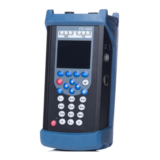
Device Description The parts of the device are explained in the sections that follow. Front Panel Status LEDs Status Bar Display Keyboard Power On/Off Indicator On/Off Button 10 Gigabit Ethernet Analyzer... -
Page 20: Keyboard
(Yes), the laser will be enabled and the Laser LED will be lit red (refer to LEDs on page 11). To disable the laser, press again. Depending on the 10G or 1G mode SFP+ or SFP laser is turned on. Function keys Cursor keys ETS-1000G... -
Page 21: Leds
Device Description LEDs Icon Description Numeric, character and symbol keys. Digits, letters and characters that can be input using the numeric keyboard. LEDs Color State Description 10G, 1st LED Green LED is A connection to the 10G constantly on. equipment being tested is established. - Page 22 LED is A test is being performed. constantly on. Green LED is flashing. The Loopback mode is enabled. — LED is off. The Loopback mode is disabled; testing is not performed. Laser LED is Laser is enabled (SFP/SFP+). constantly on. ETS-1000G...
-
Page 23: Status Bar
Device Description Status Bar The LED which is located at the bottom of the device's clipboard is lit when the external power supply is connected: Green - batteries are charged, Green (flashing) - batteries are being charged, Green (blinking) - the device's SW versions are being updated. ... -
Page 24: External Connectors
The functions of determining the packet jitter and generating test traffic are started on the same port. CTR (complex traffic) Generating/receiving complex traffic. External Connectors The layout of external connectors on the top and side panels of the device is shown in following figures ETS-1000G... -
Page 25: Control Menu Structure
Connecting to a PC via the USB interface DC IN External power unit connector Control Menu Structure The main menu of the ETS-1000G device consists of three submenus (hereinafter referred to as menus). To switch between them, use the following keys: (ETS-1000G Setup), (ETS-1000G Tools), (ETS-1000G Tests). - Page 26 Device Description Control Menu Structure ETS-1000G...
- Page 27 Device Description Control Menu Structure 2. ETS-1000G Tools. ETS-1000G Tests. 10 Gigabit Ethernet Analyzer...
-
Page 29: Rfc 2544
Owing to an opportunity of making an analysis of throughput, latency, frame loss rate and limit load, these methods are currently are a de facto standard for evaluating the performance of Ethernet-based networks. ETS-1000G allows performing four standard tests in compliance with RFC 2544. Throughput Analysis... -
Page 30: Latency Analysis
On the receiving side the label is identified and a Tb value (the time when the labeled packet was received) is recorded. A latency is a difference (Tb - Ta). The analysis results are used for calculating an average latency. ETS-1000G... -
Page 31: Frame Loss Rate Analysis
RFC 2544 Frame Loss Rate Analysis Frame Loss Rate Analysis Note: An analysis of frame loss rate is necessary for checking the network's capability to support real-time applications (which do not provide for retransmission), as a high frame loss rate causes the deterioration of QoS. An analysis of frame loss rate allows calculating the percentage of frames that a network element has failed to transmit in case of steady load due to the shortage of hardware resources. -
Page 32: Back To Back Analysis
If it turns out to be equal to the quantity of sent frames, the test will be finished. If the quantity of packets on the output of DUT is less than the quantity of transmitted packets, the time will be reduced and the test will be repeated. ETS-1000G... -
Page 33: Preparing Rfc 2544 For Analysis
MAC s A sender's MAC address. MAC d A destination MAC address. IP s A sender's IP address. IP d A destination IP address. MAC r A router's MAC address. MAC 1 A MAC address of ETS-1000G. 10 Gigabit Ethernet Analyzer... - Page 34 A router. To test the networks which include the devices operating on the data link layer of the OSI model, for example, a switch, ETS-1000G should be connected according to the diagram. In this case the traffic being generated by the device should be redirected back via setting up a loopback.
-
Page 35: Topology
Preparing RFC 2544 for Analysis Topology Topology Remote IP Remote device IP address (see Asymmetric Test on page 45) Direction Testing direction: both — select if you want to perform measurement of both direction (from local device to remote and from remote device to local);... -
Page 36: Main Header Parameters
MAC address. If there is at least one router between the source and the destination, the MAC address of the router which is nearest to the source should be specified as the destination MAC address. ETS-1000G... -
Page 37: Additional Header Parameters
Preparing RFC 2544 for Analysis Additional header parameters There is an option to automatically substitute MAC addresses and IP addresses: Press (when Src. MAC or Dst. MAC is selected) to substitute the MAC address of test port which has been specified using the Interface Parameters menu for the current MAC address. - Page 38 Interface Parameters > VLAN for the VLAN settings. Press (when MPLS is selected) to automatically substitute the settings of test port which have been specified using the menu Interface Parameters > MPLS for the MPLS settings. ETS-1000G...
- Page 39 Preparing RFC 2544 for Analysis Additional header parameters VLAN setting VLAN Selecting the number of labels (1 - 3, Off). A 12-bit VLAN identifier. It is a number in the range from 0 to 4095. It uniquely defines the VLAN which a frame belongs to.
- Page 40 Preparing RFC 2544 for Analysis Additional header parameters MPLS setting Number of Labels Select the number of labels (1 - 3, Off). Label The label value. MPLS COS The Class of Service of a packet. The time-to-live of a labeled packet. ETS-1000G...
-
Page 41: Select The Frame Size
Preparing RFC 2544 for Analysis Select the Frame Size Select the Frame Size There are two ways to set the size of the frames to be transmitted: 1. To select standard sizes in compliance with RFC 2544 (using default)): 64, 128, 256, 512, 1024, 1280 and 1518 bytes. In this case it is possible to additionally set one frame of a random size. -
Page 42: Setting Test Parameters
To optimize the speed and to increase the efficiency of making an analysis, ETS-1000G provides an option to change the standard values of test parameters (defined by RFC 2544). Test results are represented in the tabular and graphical forms according to RFC 2544 recommendation. - Page 43 Preparing RFC 2544 for Analysis Setting Test Parameters Trial, s The period of time during which the test should be per- formed for each frame size specified in the settings (1-3600 s). Resolution, % Resolution at which the throughput search should be per- formed.
- Page 44 If the Throughput value is selected ( ), the Latency test will be performed using the load value obtained as a result of the Throughput test. If the Manually value is selected ), then user-defined values will be used for perform- ing the test. ETS-1000G...
- Page 45 Preparing RFC 2544 for Analysis Setting Test Parameters Parameters of the Frame Loss Rate Test Enabled Enabling/disabling the deviation loss rate analysis. Trial, s The period of time during which the test should be per- formed for each frame size specified in the settings (1-3600 s).
- Page 46 The number of test reiterations for each frame size config- ured in the settings. Trial, s The period of time during which the test should be per- formed for each frame size specified in the settings (2-3600 s). Rates (L1) Open the Rates (L1) menu. ETS-1000G...
- Page 47 Preparing RFC 2544 for Analysis Setting Test Parameters Advanced Settings Wait time, ms The time between completing a test iteration and sending a learning frame. Learn time, ms The interval between sending a learning frame and starting the test. According to RFC 2544, the interval is 7000 ms (2000 ms are allocated for receiving residual frames, 5000 ms are allocated for stabilization of the device under test), and the duration of learning is 2000 ms.
-
Page 49: Analyzing Rfc 2544
Analyzing RFC 2544 To start tests that are based on RFC 2544, open the RFC-2544 menu and press (Start). All the selected tests will be conducted. To conduct tests selectively, open the menu of the specific test and press (Start). Throughput Test Results Test results are displayed in the tabular form: the frame size (in bytes), a throughput value (in %), which has been obtained as a result of the... -
Page 50: Latency Test Results
Latency Test Results The table displays an average latency value (in ms) for each data frame size specified in the settings and the respective throughput value (in %), which has been obtained as a result of the Throughput test. ETS-1000G... - Page 51 Analyzing RFC 2544 Latency Test Results The diagram shows a column for each frame size whose height corresponds to an average latency value (in ms). 10 Gigabit Ethernet Analyzer...
-
Page 52: Frame Loss Rate Test Results
(in %). To select the unit of measurement, including Mbps L2, Mbps L3, Mbps L4 or %, press The diagram shows dependence of the frame loss rate (in %) on the load (in %) for each frame size specified in the settings. ETS-1000G... -
Page 53: Back To Back Test Results
Analyzing RFC 2544 Back to Back Test Results Back to Back Test Results The table lists the load defined in the test settings and the time it takes the device to process the limit load for each packet size. If the time during which the device endures the maximum load cannot be determined, the test status column will display Error and the Time, s column will be filled with dashes. -
Page 54: Saving Test Results
In the mode of testing based on RFC 2544, press (Save/Load) to open the menu which allows displaying information about saved measurements ), saving test results and parameters ( ), loading ( ) and deleting ( ) saved measurement results and parameters. ETS-1000G... -
Page 55: Asymmetric Test
Therefore, the test traffic transmission is produced in one selected by the user direction. By testing two ETS-1000G should be used: local and remote. On the local device the test parameters are set. The remote device is on the other end of asymmetric channel. -
Page 56: Testing Example
To perform measurement in the direction from local device to remote, do the following: 1. Make sure that the local and remote device support asymmetric test function: in the ETS-1000G. Setup > Device settings > Options menu list of options should contain XAT option. ETS-1000G... - Page 57 2. Connect the local and remote device according to the scheme shown in the scheme image on this page. 3. On the local and remote device switch to the ETS-1000G. Setup > Network Setup menu and set: Interface – Test...
- Page 58 Connecting to remote port... — occurs immediately after the test start. No route to host — occurs if the local device is unable to connect to the remote device. Connection is lost — occurs if the remote device is not responding after the connection is established. ETS-1000G...
- Page 59 Asymmetric Test Testing Example Remote unit is busy — occurs when the remote device is already under test. Asymm. BERT at L1 is not supported — occurs when you try to perform BERT on the first level. Note: The Unit is used for remote testing message is displayed on the screen of the remote device during the test.
- Page 60 XAT option. 2. Connect the local and remote device according to the scheme shown in the image. 3. On the local and remote device switch to the ETS-1000G. Setup > Network Setup menu and set: Interface - Test...
-
Page 61: Complex Traffic
Complex Traffic The complex test traffic generation function1 allows creating up to 10 data streams with various parameters. It can be used for checking whether the priority assignment function is properly implemented in the device being tested and for simulating various workload profiles. Tests Opening the Complex Traffic: Report screen (for starting a test, displaying measurement results). - Page 62 (Diagram) to open the screen which contains the graphical representation of test results. The diagram shows a column for each stream whose height corresponds to the respective frame loss value. Press (Save/Load) to open the Results menu. Press to open the Complex Traffic: latency screen. ETS-1000G...
- Page 63 Complex Traffic Current data deference. Minimum data deference. Average data deference. Maximum data deference. Press again to open the Complex Traffic: Frames screen. The screen displays the number of transmitted packets (Tx) and the number of received packets (Rx) for each stream. 10 Gigabit Ethernet Analyzer...
- Page 64 Complex Traffic Streams Quantity of data streams (1-10). Duration Duration of generating the specified quantity of streams (1-2886 s). Header Opening the Header menu. Frames Opening the Frames menu. Rates (L2) Opening the Rates (L2) menu. ETS-1000G...
- Page 65 Complex Traffic To select the number of the stream to be adjusted, use the keys Frame sizes should be set manually within the range from 64 to 9600 bytes for each stream. A data rate value (L2) should be specified in percentage terms ( Kbps ( ) or Mbps ( 10 Gigabit Ethernet Analyzer...
-
Page 66: Complex Traffic Mpls Setting
Complex Traffic MPLS Setting Complex Traffic MPLS Setting The label stack to be used for testing is set using the Label Stack menu: ETS-1000G. Measurements > Complex Traffic > Setup > Header > Advanced > MPLS. Labels Select the number of labels (from 1 to 3) to be added to an outgoing packet. -
Page 67: Loopback
Loopback The loopback feature is used for testing networks in compliance with RFC 2544, measuring BER and solving some other tasks. It allows looping back the traffic coming to the device on the four OSI layers. On the physical layer (L1) all incoming traffic is left unchanged and redirected back. - Page 68 Off – disable the loopback feature, 1 – the physical layer, 2 – the data link layer (MAC), 3 – the network layer (IP), 4 – the transport layer (TCP/UDP). ET-Discovery Open the ET-Discovery menu. Open the OAM menu. ETS-1000G...
-
Page 69: Oam
An important feature of the OAM protocol consists in providing an opportunity of enabling the Loopback mode on a remote device. To establish a connection between the ETS-1000G device and a remote device over the OAM protocol and to enable the Loopback mode, it is necessary to execute the following procedure: 1. - Page 70 Ethernet OAM commands received from the remote device. Passive – the passive mode. In this mode the port cannot initiate enabling the Loopback feature, it can only respond to the Ethernet OAM commands received from the remote device. Off – OAM is disabled. ETS-1000G...
- Page 71 Discovery A remote network device detection status. The possible statuses are: Fault — the initial state. A connection to the remote device is not established. Send local — send OAMPDU with information about supported operating modes. Passive wait — wait for OAMPDU with information about ...
- Page 72 Support for the notification of connection errors. Var. retrieval Support for reading the variables used for the evaluation of link quality. LB status A status of the Loopback mode on the remote device. Note: ETS-1000G doesn't support the unidirectional, link events and var. retrieval features. ETS-1000G...
-
Page 73: Discovery
(ETS-1000G) or the remote loopback device. According to the test diagram, it is possible to enable the Loop-back mode successively on several devices ETS-1000G, which can belong both to different subnets or to the same subnet. 10 Gigabit Ethernet Analyzer... - Page 74 To obtain data on the remote device and ensure that the Loopback mode can be enabled, follow the procedure below: 1. Connect ETS-1000G to the network according to the diagram shown in the previous page. 2. Open the Network Parameters menu, specify the port's IP address or make sure that the device has received the correct IP address via DHCP .
-
Page 75: Tcp/Ip Tests
12 TCP/IP Tests The tests which are described in this section are used for diagnostics in the networks containing the devices which ensure the switching and routing of the data being transmitted. The TCP/IP tests which are implemented in the device allow detecting the problems relating to the network configuration, checking the network connectivity, determining data transmission routes, checking the operability of data links and estimating their occupancy. - Page 76 Open the Ping Setup menu. (Setup) Open the menu for saving test results. (Save/Load) 4. Set up the test parameters in the Ping Setup menu. IP address The IP address of the node whose accessibility is to be checked. ETS-1000G...
- Page 77 TCP/IP Tests Ping Packet Size The size of an ICMP packet (in bytes). Count The quantity of packets to be sent (from 0 to 9999). If the zero value is selected, the packets will be sent until a user presses (Stop) Timeout The timeout for receiving a response to a ping request (in ms).
- Page 78 (with the same serial number). The value in the timeout line indicates the number of packets for which the timeout for receiving a response to a ping request has expired. ETS-1000G...
-
Page 79: Traceroute
TCP/IP Tests Traceroute Traceroute The Traceroute tool is used for determining data routes and allows diagnosing the availability of intermediate network devices. During the test a sequence of frames is sent to the specified node and the system displays information about all the intermediate routers through which the data have been relayed on the way to the end node. - Page 80 (Start). The test will be started. As it is being per lines containing the following data (from left to right) are displayed in the screen: the number of an intermediate node, the IP address of an intermediate node, the response time. ETS-1000G...
-
Page 81: Dns Lookup
TCP/IP Tests DNS Lookup If the timeout for receiving a response from an intermediate node has expired, the asterisk character (*) will be displayed in the line containing results. An example of test results is shown in the following image. DNS Lookup The DNS lookup tool allows detecting faults in the operation of NS servers. - Page 82 4. Select the Host menu item and specify the domain name of the node. 5. Press (Start). The IP address of the node will be displayed in the IP menu item. If the IP address fails to be determined, the zero IP address (0.0.0.0) will be displayed in the IP menu item. ETS-1000G...
-
Page 83: Arp Request Monitor
TCP/IP Tests ARP Request Monitor ARP Request Monitor The ARP monitor tool allows monitoring the ARP responses being transmitted in the network and intercept the device IP and MAC addresses which are contained in them. To perform the test, follow the procedure below: 1. -
Page 84: Tcp Client
To establish a connection, follow the procedure below: 1. Connect the device to the network according to the diagram shown in this chapter. 2. Set up a network connection (refer to Network Parameters on page 103). 3. Open the TCP Client menu. ETS-1000G... - Page 85 TCP/IP Tests TCP Client Establish a TCP connection. (Open) Open the TCP Client. Setup menu. (Setup) Open the menu for saving test results. (Save/Load) 4. Open the TCP Client. Setup menu and adjust the connection parameters: Enter the domain name or the IP address of the node. ...
- Page 86 Reference Tables on page 143. Web pages are transmitted over HTTP . This protocol defines an HTTP GET request. It can be used for checking whether a server responds to HTTP requests and obtaining content of the specified resource. ETS-1000G...
-
Page 87: Bert
13 BERT BERT (Bit Error Rate Test) is a test that allows determining the main bit index of link quality, the bit error rate, i.e. the number of bit errors divided by the total number of transferred bits. A binary sequence that is known at the far end and the near end is inserted into an Ethernet frame which is transmitted to the physical media. - Page 88 The time during which there was no signal. %LOS The ratio of the time during which there was no signal to the time that has elapsed since the beginning of the test (in percentage terms). Setup Open the BERT Setup menu. ETS-1000G...
- Page 89 BERT Note: LSS is a state when there is no synchronization with the data being received and it is impossible to evaluate the BER parameter. The possible causes of the loss of synchronization are: Inconsistency of test sequences (for example, PRBS 2e15 is set at the ...
- Page 90 If Constant is selected, then the frames whose size is set using the Frame menu item will be used for testing. Frame Set the data frame size. Topology Switch to the Topology menu. Header Open the Header menu. ETS-1000G...
-
Page 91: Bert Mpls Setting
BERT BERT MPLS Setting BERT MPLS Setting The label stack to be used for testing is set in the MPLS menu. Labels Select the number of labels (from 1 to 3) to be added to an outgoing packet. Label The label value. MPLS COS The Class of Service of a packet. - Page 92 BERT Connection Options Testing on the physical layer (option 2) Testing on the data link/network layer (option 1) Testing on the data link/network layer (option 2) ETS-1000G...
- Page 93 BERT Connection Options Testing on the data link/network layer (option 3) 10 Gigabit Ethernet Analyzer...
-
Page 95: Delay Variation
14 Delay Variation During an analysis of Ethernet-based networks, an important task is to determine the packet jitter and latency. According to RFC 4689[5], the packet jitter is the absolute difference of propagation of two successively received packets which belong to the same data stream. This parameter is used for evaluating the network's capability to transmit the deference-sensitive traffic, such as video or voice. - Page 96 To start determining the packet jitter and latency for the packets being received to 10G/1G port, press (Start). To select Jitter or Latency measurement results press To open the screen which contains information about the jitter/latency distribution, press (Distribution). ETS-1000G...
- Page 97 Delay Variation The screen displays two columns. The first one contains the limits of subintervals, the second one contains the number of packets (in percentage terms) for which the jitter/latency belongs to the specified subinterval. The upper interval limit can be set in the Delay Variation > Setup menu.
- Page 98 Delay Variation test. Jit. threshold, ms The threshold jitter value. Lat. threshold, ms The threshold latency value. Duration The Delay Variation measurement duration. Traffic generator Open the Traffic Generator menu. ETS-1000G...
-
Page 99: Traffic Generator
15 Traffic Generator The test traffic generation option allows to produce different types of test traffic: static, MAC flood, VLAN flood, IP flood. MAC, IP and VLAN flood modes allow to consume the limited addressable memory of the DUT and to check if it has any protection against this kind of attacks. - Page 100 Frame size (any value within the range from 64 to 9600 bytes). Header Open the Header menu. The time that has elapsed since the beginning of the traffic generation. The time that is left until the end of the traffic generation. ETS-1000G...
-
Page 101: Static Traffic
It is possible to generate test traffic and measure the packet jitter and latency distribution on port 10G/1G of the device, and also to generate test traffic on the local device's port (ETS-1000G) and perform measurement on the remote device's port (ETS-1000G). - Page 102 Traffic Generator Static Traffic If ETS-1000G is connected to the network to conduct, for example, the Packet jitter test, do the following: 1. Open the Network setup menu, specify the IP address of 10G/1G port or make sure that the device has received the correct IP address via DHCP .
- Page 103 Traffic Generator Static Traffic Disable the test traffic generator. Specify the required threshold value. Specify measurement duration. 4. Open the Traffic generator menu on the local device and enable the test traffic generation feature. 5. Open the Delay Variation > Summary menu on the remote device and press (Start).
-
Page 104: Mac/Ip And Vlan Flood
To perform the test you need to: 1. Connect 10G/1G port of the ETS-1000G to the NUT/DUT. 2. Open the Network Setup menu on the local and remote devices, specify the IP address of test port or make sure that the device has received the correct IP address via DHCP. -
Page 105: Statistics
16 Statistics ETS-1000G enables gathering and displaying statistics of the traffic being received and transmitted on the physical, data link and network layers in compliance with RFC 2819. Statistical data are displayed on several screens. To switch between the screens, use . -
Page 106: Statistics Of Frame Types
Statistics Statistics of Frame Types Statistics of Frame Types Broadcast Broadcast frames. Multicast Multicast frames. Unicast Unicast frames. The number of received frames. The number of transmitted frames. ETS-1000G... -
Page 107: Statistics Of Frame Sizes
Statistics Statistics of Frame Sizes Statistics of Frame Sizes Size The size of a frame (in bytes). The number of received frames. The number of transmitted frames. 10 Gigabit Ethernet Analyzer... -
Page 108: Statistics For Layers
Statistics Statistics for Layers Statistics for Layers Layer 2 The number of received (Rx) frames on the data link layer. Layer 3 The number of received (Rx) frames on the network layer. ETS-1000G... -
Page 109: Statistics Of Frame Errors
Statistics Statistics of Frame Errors Statistics of Frame Errors The number of received frames which have an invalid checksum. Runt The number of received packets which do not exceed 64 bytes with a correct checksum. Jabber The number of received packets which exceed 1518 bytes in size and have an invalid checksum. -
Page 111: Saving Test Results And Statistics
17 Saving test results and statistics The Results menu is used for viewing information about saved measurements ( ), saving test results (including statistics) and parameters ( ), loading ( ) and deleting ( ) saved measurement results and parameters. To view detailed information about an entry, press To save data: Select the number to be used for saving measurement data. - Page 112 Saving test results and statistics To load saved measurement results and test parameters: Select the entry number. Press (Load). To delete saved measurement results: Select the number of the entry to be deleted. Press (Delete). Press (Yes). ETS-1000G...
-
Page 113: Network Parameters
18 Network Parameters Interface Select the interface (Test or LAN) to be configured. DHCP If this feature is enabled, the DHCP server will automati- cally send the port's IP address, the subnet mask, the gate- way's IP address and the IP address of a node where the DNS database resides to the tester. - Page 114 Note: The gateway's IP address and the IP address of the network node where the DNS database resides are set independently for each port. Note: MPLS is not included in the basic configuration. It is available as an option upon special request. ETS-1000G...
-
Page 115: Interface Parameters
19 Interface Parameters Interface Select the interface (Test or LAN) to be configured. Mode Select the interface mode: 10G (10 Gbps rate for 10G port with SFP+ module); 10G(WAN) (WAN-mode | 10G Ether- net, adapted to work in OC-192 networks); Auto(1G) (autonegotiation mode for 1G port);... - Page 116 The connection will be established only if the auto-negotiation mode is enabled also on remote end, and if the remote device supports at least one the same connection rates. The connection will be established at the maximum preferable rate for both device. ETS-1000G...
- Page 117 Interface Parameters Transmis- Open the Transmission menu. sion Reception Open the Reception Rules menu. Besides, the MPLS parameters specified using the Reception and Transmission menus are displayed on the screen. LSR address The IP address of the label-switching router's interface to which the device is connected.
- Page 118 Interface Parameters Labels Select the number of labels (from 1 to 3) to be added to the packet to be transmitted. Label The label value. MPLS COS The Class of Service of a packet. The time-to-live of a labeled packet. ETS-1000G...
- Page 119 Interface Parameters Labels Select the number of in incoming packets. Label 1, The label value. Label 2, Label 3 10 Gigabit Ethernet Analyzer...
-
Page 121: Device Settings
20 Device Settings Display Settings LEDs bright. Adjust the intensity level of LEDs on the clipboard of the device. Backlight Adjust the display illumination brightness. Chromaticity Adjust the image color. Contrast Adjust the image contrast. Keyboard beep Enable/disable keypad tones. LCD auto off This field can be used for setting the following values of the automatic display illumination switch-off time: Off, 20... -
Page 122: General Settings
Device Settings General Settings General Settings Language Change the interface language. Date Set the date. Time Set the time. ETS-1000G... -
Page 123: Information
Device Settings Information Information The MCU program version. SYS FPGA The system FPGA microcode version. EXP FPGA The expansion FPGA microcode version. BOOT The loader version. FILES The file system version. HWREV The mainboard and expansion card version. The serial number. MAC TEST The MAC address of test port. -
Page 124: Sfp/Sfp+ Information
The operation time of the device since the previous activa- tion until the previous deactivation. SFP/SFP+ Information The screen displays information about the vendor, the part number and the supported data transfer modes of the SFP/SFP+ module. Storage Battery ETS-1000G... -
Page 125: Temperature
The screen displays the current temperature of different device components. Option Control Options are features of ETS-1000G which are available upon special request. To activate options, it is necessary to enter the key which has been generated for the specified serial number of the device in the Options menu directly on the device or using the remote control command ats (refer to Annex B). -
Page 127: Profiles
21 Profiles ETS-1000G provides for an opportunity of creating profile of settings, which enables a user to adjust main tests and network interfaces promptly when performing tests. Each setting profile includes: Setting of topologies, headers and frame sizes for such tests as RFC ... -
Page 129: Event Logging
22 Event Logging The event logging system outputs messages about occurred events in the Log menu, and also to the console terminal in case of establishing a connection to the device through the USB interface or the remote control over TELNET. The events to be logged include: Starting/stopping a test, ... - Page 130 Event Logging To empty the buffer, use (Clean). (Results) is used for opening the Results menu for saving messages about occurred events. Besides, the messages are also saved when saving results and settings of any tests. ETS-1000G...
-
Page 131: Remote Control
In this case the recovery can only be implemented at the service center. The most recent SW versions for ETS-1000G are available in the Internet (http://www.myexfo.com). The current software version numbers can be viewed in the Information menu (Device Settings > Information). -
Page 132: Connecting To A Pc Via The Usb Interface
If you use HyperTerminal, take the following actions to establish a connection to the device via the USB interface. 1. Turn on ETS-1000G. 2. Connect the device to the USB port of the PC using the cable included in the delivery set. -
Page 133: Remote Control Over Telnet
OS Windows, as well as third-party terminal programs that enable file transfer over TELNET. To control ETS-1000G over TELNET, take the following actions. 1. Connect the device to a PC through test or the LAN port. -
Page 134: Remote Control Through The Www Interface
To take a screenshot of the device's screen, it is necessary to: 1. Connect the device to a PC through test port or the LAN port. 2. Set up a network connection (refer to Network Parameters on page 103). ETS-1000G... - Page 135 Remote Control Taking Screenshots 3. Specify the following address in the address bar of the web browser: http://port IP address/sshot. 4. In a few seconds the screenshot will be displayed in the web browser window on the PC. 10 Gigabit Ethernet Analyzer...
-
Page 137: Service And Maintenance
24 Service and Maintenance To help ensure long, trouble-free operation: Always inspect fiber-optic connectors before using them and clean them if necessary. Keep the unit free of dust. Clean the unit casing and front panel with a cloth slightly dampened ... -
Page 138: Recalibrating The Unit
You should determine the adequate calibration interval for your unit according to your accuracy requirements. Under normal use, EXFO recommends calibrating your unit every two years. Battery Charging Procedure To charge the battery it is necessary to execute the following actions: 1. - Page 139 Service and Maintenance Battery Charging Procedure In the future you need to charge the battery when: the battery is partial discharged; the battery is full discharged; if the tester is not used more than 1 month. Note: Before the first use, switch on the device. Note: Battery replacement is made only by the manufacturer.
-
Page 140: Recycling And Disposal (Applies To European Union Only)
Service and Maintenance Recycling and Disposal (Applies to European Union Only) Recycling and Disposal (Applies to European Union Only) For complete recycling/disposal information as per European Directive WEEE 2002/96/EC, visit the EXFO Web site at www.exfo.com/recycle. ETS-1000G... -
Page 141: Troubleshooting
25 Troubleshooting Typical fault indications Possible cause Fault elimination method Invalid system time Set the system time. The device cannot be turned on. The reset button has been The storage battery is Turn the external power pressed. discharged. supply on, charge the storage battery. -
Page 142: Contacting The Technical Support Group
Contacting the Technical Support Group To obtain after-sales service or technical support for this product, contact EXFO at one of the following numbers. The Technical Support Group is available to take your calls from Monday to Friday, 8:00 a.m. to 7:00 p.m. -
Page 143: Warranty
26 Warranty General Information EXFO Inc. (EXFO) warrants this equipment against defects in material and workmanship for a period of one year from the date of original shipment. EXFO also warrants that this equipment will meet applicable specifications under normal use. -
Page 144: Liability
Liability Liability EXFO shall not be liable for damages resulting from the use of the product, nor shall be responsible for any failure in the performance of other items to which the product is connected or the operation of any system of which the product may be a part. -
Page 145: Exclusions
Warranty Exclusions Exclusions EXFO reserves the right to make changes in the design or construction of any of its products at any time without incurring obligation to make any changes whatsoever on units purchased. Accessories, including but not limited to fuses, pilot lamps, batteries and universal interfaces (EUI) used with EXFO products are not covered by this warranty. -
Page 146: Service And Repairs
5. Return the equipment, prepaid, to the address given to you by support personnel. Be sure to write the RMA number on the shipping slip. EXFO will refuse and return any package that does not bear an RMA number. -
Page 147: Exfo Service Centers Worldwide
Warranty EXFO Service Centers Worldwide EXFO Service Centers Worldwide If your product requires servicing, contact your nearest authorized service center. EXFO Headquarters Service Center 400 Godin Avenue 1 866 683-0155 (USA and Canada) Quebec (Quebec) G1M 2K2 Tel.: 1 418 683-5498... -
Page 149: A Specifications
Specifications Interfaces 10G SFP+ 10GBASE-SR/SW, 10GBASE-LR/LW, 10GBASE-ER/EW 1G SFP 1000BASE-SX, 1000BASE-LX, 1000BASE-EX, 1000 BASE-T RJ-45 10/100/1000 BASE-T USB type B Control interface LAN 10/100 Ethernet Control interface Testing Transmission rates 10 Mbps, 100 Mbps, 1Gbps, 10 Gbps Supported frame Ethernet II, IPv4, UDP , TCP formats Setting of frame Source/destination MAC address, VLAN ID, VLAN priority,... - Page 150 TELNET, sending a HTTP GET request. Loopback Layers: the physical layer, the data link layer with support for VLAN, the network layer, the transport layer. ET discovery Enabling the Loopback mode on a remote analyzer (ETS-1000G) or a remote loopback device. ETS-1000G...
-
Page 151: General Features
Specifications General Features Enabling the Loopback mode for the data link layer on a remote device using the OAM protocol in compliance with IEEE 802.3ah standard. Remote control Controlling the device in the terminal mode over TELNET, through the WWW interface. Conducting tests, setting parameters, obtaining measurement results. -
Page 152: Delivery Options
Switch stability control (see Traffic Generator on page 89) Traffic generation with random source MAC addresses or VLAN labels (MAC/VLAN flooding). Router stability control (see Traffic Generator on page 89) Traffic generation with random destination IP addresses (IP flooding). ETS-1000G... -
Page 153: B Reference Tables
Reference Tables Traffic Types and Priorities Value Description Background 0 (Default) Best Effort Excellent Effort Critical Application Video Voice Internetwork Control Network Control The Network Control and Internetwork Control traffic types are reserved for network control messages. Priorities 4 and 5 can be used for deference-sensitive traffic, such as video or voice. -
Page 154: Precedence Values
0001 Minimize monetary To minimize the cost. It is used when it is cost necessary to minimize the data transmission cost. 0000 All normal Normal service. In this case a packet is routed according to a provider's decision. ETS-1000G... -
Page 155: Class Of Service And Dscp Values
Reference Tables Class of Service and DSCP Values Class of Service and DSCP Values Traffic Class Values of the DSCP field Default 000 000 AF11 001 010 AF12 001 100 AF13 001 110 AF21 010 010 AF22 010 100 AF23 010 110 AF31 011 010... -
Page 156: Ecn Values
CE (Congestion Experienced) — confirmed congestion. ECN (Explicit Congestion Notification) — an explicit notification of congestion. Setting bits in this field allows routers to detect congestion on the data transmission path to the specified network node without discarding a packet. ETS-1000G... -
Page 157: Tcp/Ip Port Numbers
Reference Tables TCP/IP Port Numbers TCP/IP Port Numbers Port number Description (protocol) 21 (FTP) File Transfer Protocol 22 (SSH) A secure protocol for remote control and file transfer 23 (TELNET) A protocol for accessing a remote network device 25 (SMTP) An e-mail transfer protocol 80 (HTTP(WWW)) A protocol that is used by web browsers and web services for... -
Page 158: Test Sequences
Digits, Letters, and Characters Digits Letters Characters — @ / - a b c — d e f — g h i — j k l — m n o — p q r s — t u v — ETS-1000G... - Page 159 Reference Tables Digits, Letters, and Characters Digits Letters Characters w x y z — — . , : ; — — 10 Gigabit Ethernet Analyzer...
-
Page 161: C Remote Control Commands
Remote Control Commands Remote control commands (a console terminal) Command Description An empty command which is used for checking a connection. Restart the device. Display the current measurement results. ATMN Display the saved measurement results which were assigned serial number N (N = 1...10) ATMA Display all saved measurement results. - Page 162 The load rate for the throughput analysis. show rfc2544 throughput resolution The resolution value for the throughput analysis. show rfc2544 throughput threshold The loss threshold value for the throughput analysis. ETS-1000G...
- Page 163 Remote Control Commands Remote control commands (a console terminal) Command Information to be output to the console show rfc2544 frames [1-9] size The frame size defined by a user (or a standard value that complies with RFC 2544). show rfc2544 frames [1-9] enable Display whether the frame size is to be used for performing the test.
- Page 164 The destination UDP port number. show ctraf header vlan count The number of VLAN tags. show ctraf header vlan [1-3] id The VLAN identifier value. show ctraf header vlan [1-3] priority The traffic priority value. ETS-1000G...
- Page 165 Remote Control Commands Remote control commands (a console terminal) Command Information to be output to the console show ctraf header mpls count Select the number of labels. show ctraf header mpls [1-3] label s The label value. how ctraf header mpls [1-3] cos The Class of Service of a labeled packet.
- Page 166 Display whether a random frame size or a fixed frame size is set. show bert level The OSI layer on which the test is to be conducted. show bert pattern A standard test sequence. show bert user-pattern A user-defined test sequence. ETS-1000G...
- Page 167 Remote Control Commands Remote control commands (a console terminal) Command Information to be output to the console show bert rate The stated load, Kbps show bert duration The measurement duration. bert start Start the BERT test. bert stop Stop the BERT test. bert results Results of the BERT test.
- Page 168 The frame sizes to be used for testing. show txgen frame type Display whether a random frame size or a fixed frame size is set. show txgen duration The duration of test traffic generation. show txgen rate The stated load, Kbps or % ETS-1000G...
- Page 169 Remote Control Commands Remote control commands (a console terminal) Command Information to be output to the console txgen start Start the generation of test traffic. txgen stop Stop the generation of test traffic. txgen results Results of generating test traffic. Loopback show loopback layer The loopback layer.
- Page 170 N (N = 1...10). results load N Load the saved measurement results which were assigned serial number N. results show Display the current measurement results. results show N Display the saved measurement results which were assigned serial number N. ETS-1000G...
- Page 171 Remote Control Commands Remote control commands (a console terminal) Command Information to be output to the console results show all Display all saved measurement results. results info Display information about saved measurement results. log off/on Disable/enable the event logging system. log show Display messages about occurred events.
-
Page 172: Remote Control Commands (Telnet). Configuration Mode
/ dscp Select the IP Precedence field and the Type of Service field or the DSCP field for inserting. rfc2544 header dscp text Set the value of the DSCP field, 8 bits. rfc2544 header precedence int Set the frame priority value. ETS-1000G... - Page 173 Remote Control Commands Remote control commands (TELNET). Configuration mode Command Action rfc2544 header tos text Set the Type of Service of a packet. rfc2544 throughput duration int Set the test duration for the throughput analysis. rfc2544 throughput enabled no / yes Disable/enable the throughput analysis.
- Page 174 Set the value of the DSCP field, 8 bits. ctraf nstreams int Specify the number of data streams. ctraf stream int Specify the number of the stream to be adjusted. ctraf duration int Set the duration of generating the specified quantity of streams. ETS-1000G...
- Page 175 Remote Control Commands Remote control commands (TELNET). Configuration mode Command Action ctraf header src mac Set the source MAC address. XX:XX:XX:XX:XX:XX ctraf header src ip i.i.i.i Set the source IP address. ctraf header src udp int Set the source UDP port number. ctraf header dst mac Set the destination MAC address.
- Page 176 Select the OSI layer on which the test is to be conducted. bert pattern user / crtp / 2e11-1 / 2e15-1 Select a standard test sequence or a user-de / 2e20-1 / 2e23-1 / 2e29-1 / 2e31-1 fined test sequence. bert user-pattern hex Specify the user-defined sequence. ETS-1000G...
- Page 177 Remote Control Commands Remote control commands (TELNET). Configuration mode Command Action bert rate Specify the required load. bert duration hh.mm.ss Set the measurement duration. Packet jitter jitter txgen off / on Disable/enable the test traffic generator. jitter threshold int Set the threshold jitter value. jitter duration hh.mm.ss Set the jitter measurement duration.
- Page 178 / on Disable/enable the DHCP feature for port Test. network ip i.i.i.i Set the IP address of port Test. network subnet i.i.i.i Set the subnet mask for port Test. network gateway i.i.i.i Set the gateway's IP address for port Test. ETS-1000G...
- Page 179 Remote Control Commands Remote control commands (TELNET). Configuration mode Command Action network dns i.i.i.i Set the IP address of the network node where the DNS database resides for port Test. lan dhcp off / on Disable/enable the DHCP feature for the LAN port.
- Page 180 (write-protected or not). profile show [n] Display the content of profile n. General commands exit Exit the configuration mode. help List available commands. time HH:MM:SS Set the time. date DD-MM-YYYY Set the date. ETS-1000G...
-
Page 181: D Ethernet Frame Structure
Ethernet Frame Structure Destination MAC Address — A destination MAC address. A 6-byte field that contains an IP address of the network node to which the frame is addressed. Source MAC Address — A source MAC address. A 6-byte field that contains an address of the frame sender. - Page 182 CFI — Canonical Format Indicator. A one-bit flag that is always equal to zero for Ethernet frames. VLAN ID — VLAN Identifier (VID). A 12-bit VLAN identifier that is defined in 802.1Q standard [9]. It uniquely identifies the VLAN a frame belongs to. ETS-1000G...
-
Page 183: E Glossary
Glossary Port A physical interface with the medium being tested. 10Base-T The standard for data transmission at the rate of 10 Mbps over the Ethernet network using a twisted pair cable. 100BASE-T (100BASE-TX) The standard for data transmission at the rate of 100 Mbps over the Ethernet network using a twisted pair cable. - Page 184 A test that determines the percentage of frames that a network element has failed to transmit in case of steady load due to the shortage of hardware resources. File Transfer Protocol. A protocol that supports le transmission in computer networks. ETS-1000G...
- Page 185 Glossary Gateway A network device that allows connecting two or more different-type network systems and transforms the data streams being transmitted between them. ICMP Internet Control Message Protocol. A network protocol that is a part of the TCP/IP protocol stack. It is mainly used for the transmission of error messages and messages about other exceptions that occur during data communication.
- Page 186 Registered Jack. A standardized physical interface that is used for interconnecting telecommunications equipment. RJ-45 A connector that complies with the Registered Jack standard and is used for connecting twisted pairs in Ethernet networks. Runt frame A data packet that doesn't exceed 64 bytes with a correct frame-check sequence. ETS-1000G...
- Page 187 Glossary Service Level Agreement. The main document that regulates mutual relations between a service provider and a customer. Transmission Control Protocol. A standard transport layer protocol that belongs to the TCP/IP protocol family and enables the reliable duplex streaming. Throughput A test that determines the maximum data rate at which the quantity of test frames that have been transferred via DUT is equal to the quantity of frames that have been sent to it from the test equipment.
- Page 188 It ensures the reliable packet transport between two network end points. Despite the fact that lower layer protocols check whether each data transmission operation is being executed correctly, this layer ensures that the data being transmitted are additionally checked for correctness. ETS-1000G...
- Page 189 Glossary Physical layer Its peculiar task is to transmit data stream. It transmits electric and optic signals to the cable, receives them and converts them into data bits according to the digital signal coding methods. 10 Gigabit Ethernet Analyzer...
-
Page 191: Index
98 ethernet frame structure ......170 service and repairs ........136 service centers ........... 137 shipping to EXFO........136 statistics for layers ........95 frame loss rate ..........19 statistics of error frames ......99 frame loss rate test results ......39 statistics of frame sizes........ - Page 192 127 throughput ..........13 throughput parameters....... 30 throughput test results ....... 37 traceroute ........... 65 transportation requirements ..... 127 unit recalibration........128 warranty certification ......... 135 exclusions ..........135 general ..........133 liability..........134 null and void........133 ETS-1000G...
- Page 193 CHINESE REGULATION ON RESTRICTION OF HAZARDOUS SUBSTANCES NAMES AND CONTENTS OF THE TOXIC OR HAZARDOUS SUBSTANCES OR ELEMENTS NAMES AND CONTENTS OF THE TOXIC OR HAZARDOUS SUBSTANCES OR ELEMENTS CONTAINED IN THIS EXFO PRODUCT CONTAINED IN THIS EXFO PRODUCT EXFO...
- Page 194 MARKING REQUIREMENTS MARKING REQUIREMENTS Product Environmental protection use period (years) Logo Product Environmental protection use period (years) Logo This Exfo product This Exfo product EXFO EXFO Battery Battery If applicable. If applicable.
- Page 195 Tel.: 1 978 367-5600 · Fax: 1 978 367-5700 EXFO NETHAWK Elektroniikkatie 2 FI-90590 Oulu, FINLAND Tel.: +358 (0) 403 010 300 · Fax: +358 (0) 8 564 5203 TOLL-FREE (USA and Canada) 1 800 663-3936 © 2013 EXFO Inc. All rights reserved. Printed in Canada (2013-01) ...
Need help?
Do you have a question about the ETS-1000G and is the answer not in the manual?
Questions and answers