
Related Manuals for Yamaha MONTAGE M6


Summary of Contents for Yamaha MONTAGE M6
- Page 1 MUSIC SYNTHESIZER SYNTHÉTISEUR MUSICAL SINTETIZADOR MUSICAL Quick Guide Guide rapide Guía rápida...
- Page 2 If these corrective measures do not produce satisfactory results, please contact the local retailer authorized to distribute this type of product. If you cannot locate the appropriate retailer, please contact Yamaha Corporation of America, 6600 Orangethorpe Ave., Buena Park, CA90620, USA.
- Page 3 Information for users on collection and disposal of old equipment: This symbol on the products, packaging, and/or accompanying documents means that used electrical and electronic products should not be mixed with general household waste. For proper treatment, recovery and recycling of old products, please take them to applicable collection points, in accordance with your national legislation. By disposing of these products correctly, you will help to save valuable resources and prevent any potential negative effects on human health and the environment which could otherwise arise from inappropriate waste handling.
-
Page 4: Precautions
• Do not place any burning items or open flames near the • Check the power plug periodically and remove any dirt or product, since they may cause a fire. dust which may have accumulated on it. If you notice any abnormality • Insert the power plug firmly all the way into the AC outlet. Using the product when it is not plugged in sufficiently • If any of the following problems occur, immediately turn can cause dust to accumulate on the plug, possibly off the power switch and disconnect the power plug from resulting in fire or skin burns. the outlet. • When setting up the product, make sure that the AC Finally have the device inspected by Yamaha service outlet you are using is easily accessible. If some trouble or personnel. malfunction occurs, immediately turn off the power switch - The power cord or plug becomes frayed or damaged. and disconnect the plug from the outlet. Even when the - Unusual smells or smoke are emitted. power switch is turned off, as long as the power cord is not - Some object, or water has been dropped into the unplugged from the wall AC outlet, the product will not product. be disconnected from the power source. - There is a sudden loss of sound during use of the • Do not connect the product to an electrical outlet using product. - Page 5 • Do not use the product or headphones for a long period • When transporting or moving the product, always use two of time at a high or uncomfortable volume level, since this or more people. Attempting to lift the product by yourself can cause permanent hearing loss. If you experience any may result in injuries, such as back injuries, or cause the hearing loss or ringing in the ears, consult a physician. product to be dropped and broken, which could lead to • Remove the power plug from the AC outlet before other injuries. cleaning the unit. Failure to observe this may cause • Before moving the product, remove all connected cables, electric shocks. to prevent damage to the cables or injury to anyone who might trip over them. Connections • Before connecting the product to other electronic components, turn off the power for all components. Before turning the power on or off for all components, set all volume levels to minimum. • Be sure to set the volumes of all components at their minimum levels and gradually raise the volume controls while playing the product to set the desired listening level. Yamaha cannot be held responsible for damage caused by improper use or modifications to the product, or data that is lost or destroyed. Always turn the power off when the product is not in use. (DMI-11) MONTAGE M Quick Guide...
-
Page 6: Notice
NOTICE Information To avoid the possibility of malfunction/ damage to the „ About copyrights product, damage to data, or damage to other property, follow the notices below. The copyright of the “content” installed in this product belongs to Yamaha Corporation or its copyright holder. „ Handling Except as permitted by copyright laws and other relevant laws, such as copying for personal use, it is prohibited • Do not use this product in the vicinity of a TV, radio, stereo to “reproduce or divert” without the permission of the equipment, mobile phone, or other electric devices. copyright holder. When using the content, consult with a Otherwise, this product, TV, or radio may generate noise. copyright expert. • When you use the product along with an app on your If you create music or perform with the contents through the smart device, such as a smartphone or tablet, we original use of the product, and then record and distribute recommend that you enable “Airplane Mode” on the them, the permission of Yamaha Corporation is not required device to avoid noise caused by communication. regardless of whether the distribution method is paid or free • Do not expose the product to excessive dust or vibrations, of charge. or extreme cold or heat (such as in direct sunlight, near a *1: The word “content” includes a computer program, audio data, heater, or in a car during the day) to prevent the possibility Accompaniment Style data, MIDI data, waveform data, voice of disfiguration, damage to the internal components or recording data, music score, and score data, etc. - Page 7 MEMO MONTAGE M Quick Guide...
-
Page 8: Welcome
About the manuals The set of documents listed below are included with this instrument. Printed manual included with this product „ Quick Guide (this book) Provides explanations for the basic functions of the instrument. Website-based manuals The manuals provided on the website can be downloaded from the Yamaha Downloads. Connect to the Internet and enter the model name "MONTAGE M" in the Model Name or Keyword search box and click Search. Yamaha Downloads https://download.yamaha.com/ „ Operation Manual (HTML) Provides instructions on operating the instrument, as well as detailed information on the internal structure and connection of other instruments and devices. https://manual.yamaha.com/mi/synth/montage_m/index_q.html „ Data List (.xlsx and .pdf) This file contains various important lists such as the Performance list, Effect type list, Waveform list, Arpeggio type list, and MIDI implementation chart. Included accessories • Power cord (× 1) -
Page 9: About Firmware Updates
About firmware updates To implement new functions and improve operability, this instrument may be shipped with an updated version of the firmware installed. The manual for the updated version of the firmware can be downloaded from the website below. Yamaha Downloads: https://download.yamaha.com/ The firmware version of your keyboard can be checked via [UTILITY] g Settings g System. Notation in this document Model name In this document, MONTAGE M6, MONTAGE M7, and MONTAGE M8x are collectively called the “MONTAGE M.” NOTE "NOTE" indicates supplementary descriptions. MONTAGE M Quick Guide... -
Page 10: Table Of Contents
Contents PRECAUTIONS ..............2 NOTICE . -
Page 11: Features
Features The MONTAGE M synthesizers feature the built-in Motion Control Synthesis Engine, letting you create enormously complex, multi-textured sounds by combining AWM2, FM-X, and AN-X synthesis engines seamlessly and further modifying the sound using Motion control. Therefore, you can use the MONTAGE M, not just for recreating conventional sounds, but also for creating completely new sounds. What is the Motion Control Synthesis Engine? This is a powerfully comprehensive synthesis system that uses a hybrid, multi-tone-generator sound engine, and sophisticated motion controls with multiple control sources for creating complex and continuously shifting sonic textures. Hybrid sound engine Motion controls AWM2 Super Knob Generates sounds using sound files (or wave Controls multiple parameters for creating files) sampled from real instruments multi-dimensional sound changes FM-X Motion Sequencer Generates sounds by using the frequencies of Plays back the movement of the controllers waveforms to modify other waveforms you have set beforehand and changes the sound sequentially AN-X Envelope Follower Generates sounds by modifying simple waveforms and applying ‘modeling’ filters Generates sound changes that synchronize to... -
Page 12: Basic Performance Structure
„ Normal Parts (FM-X) Parts played by the FM-X sound engine. „ Normal Parts (AN-X) Parts played by the AN-X sound engine. „ Drum Parts (AWM2) Parts played by the AWM2 sound engine. A percussion instrument sound can be assigned to the Part. The Drum Parts are used for playing rhythms. NOTE • If you wish to create sounds by using default initial values, select an Init Performance. • If you wish to use this instrument as a 16-part multitimbral tone generator, use the Multi/GM Performances. These are Performances using all 16 parts, with the drums being assigned to Part 10. Performances allow you to select a sound for each Part and combine multiple Parts in sophisticated split and layer settings for playing on the keyboard. Moreover, you can create complex sounds by editing the Performances and Parts from the Edit screen and enabling the Motion Control settings. The created Performance can be saved to internal memory, or to USB flash drives connected to the instrument. You can also use Soundmondo, a sound management and sharing service, to save backups for yourself or share your Performances with others. Soundmondo: https://www.yamaha.com/2/soundmondo By combining the Expanded Softsynth Plugin for MONTAGE M (the software version of the MONTAGE M) installed on the computer and the hardware version of the MONTAGE M, you can create and manage many more Performances. The sounds you have used in your DAW for music production and the sounds you have used for live performance are shared between the software and hardware synthesizers. MONTAGE M Quick Guide... -
Page 13: How Live Set Works
Performance 16 Performance NOTE A link to the selected Performance is saved to each slot. When a Performance is edited and stored, all slots that have the link to the corresponding Performance will be updated. Live Set bank A bank is a set of Live Set pages used for managing Performances. Each bank has 16 pages of Live Sets. There are three types of banks: Preset, User, and Library. „ Preset bank The bank for registered preset Performances. Any Performances in the Preset bank you have edited cannot be saved back to the Preset bank; they must be saved to a User bank NOTE Refer to the “Data list” for the list of Preset Performances. „ User bank The bank for registered Performances you’ve edited yourself. Nothing is contained in this bank when the MONTAGE M is shipped from the factory. There are eight banks (or 128 pages) available, allowing you to register up to 2,048 Performances. You can arrange the Performances in your own custom order—for example, according to a setlist in live performance situations. „ Library bank The bank for registered Performances from the Library files. Nothing is contained in this bank when the MONTAGE M is shipped from the factory. You can register one Library file per bank. Library files can be downloaded from the Yamaha website. When you first start up the MONTAGE M, the Live Set screen for the Preset bank will be shown on the Main display. The start-up screen can be set to a Live Set or Performance screen as desired ([UTILITY] g System). MONTAGE M Quick Guide... -
Page 14: Panel Controls And Functions
Panel controls and functions This section provides an overview of the panel controls and functions. Top panel Controlling parameters in real time as Viewing the screen, switching settings, you play the keyboard, and adjusting selecting items, and entering values Selecting a sound detailed parameter values Playing the keyboard Controlling the Selecting functions such as Edit and built-in sequencer Utility Selecting a sound MONTAGE M Quick Guide... - Page 15 [PERFORMANCE] button (INFO) This calls up the Performance screen. You can press this button to switch to a different Performance view. Pressing this button while holding down the [SHIFT] button calls up the screen for checking relevant information for the Performance (INFO screen). [LIVE SET] button (REGISTER) This calls up the Live Set screen. You can press the same button to select a different Performance bank. Press this button and then tap the slot on the touchscreen, or use the Slot number and Category name selection buttons to select a slot from the Live Set page currently shown on the screen. Pressing this button while holding the [SHIFT] button opens the screen for registering the current Performance to the Live Set page. Doing this beforehand allows you to call up Performances quickly and conveniently as you play live. BANK buttons Use these buttons to select a bank. PAGE buttons Use these buttons for selecting a Live Set page. On the Category Search screen, you can use these buttons to scroll through the list of Performances. [CATEGORY] button (PART CATEGORY) Use this button to call up the Category Search function. Every time you press the button, the next Performance bank is selected. While the Performance screen is active, pressing this button opens the Performance Category Search screen for selecting a Performance. When the cursor is on a Part, pressing this button while holding down the [SHIFT] button opens the Part Category Search screen. Slot number and Category name selection buttons When the [LIVE SET] button is selected, you can use these buttons to select one of the Live Set slots, 1 to 16. When the [CATEGORY] button is selected, you can use these buttons to select a category.
- Page 16 Selecting functions such as Edit and Utility [UTILITY] button (SHOW VALUE) This calls up the UTILITY screen where you can change the overall settings for the MONTAGE M. Pressing this button while holding down the [SHIFT] button shows the values on the Main display or the Sub display if there are any values not shown graphically. [NAVIGATION] button (FX OVERVIEW) According to the Part you are editing, this calls up the map of the corresponding parameters. When you select one item from the map, the parameter setting screen for that item will be shown on the Main display. Pressing this button while holding down the [SHIFT] button calls up the screen for checking the effect overview (FX OVERVIEW screen). [EDIT/ ] button (JOB) This calls up the Performance Edit, Live Set Edit or Pattern Edit screen. While editing the Performance parameters, pressing this button allows you to use the Compare function. With the Compare function, you can check the sound before and after editing to see how the sound changes. While the Edit screen is shown, press the [EDIT/ ] button. The [EDIT/ ] button flashes, and the settings temporarily revert to the state before the edit. Press the [EDIT/ ] button again to enable the newly edited settings again. Pressing this button while holding down the [SHIFT] button calls up the screen for Job settings (JOB screen). [SHIFT] button Hold down this button along with another button enables you to call up the alternate function printed in red at the bottom of each button. For the list of functions, refer to the Operation Manual. [DAW REMOTE] button This calls up the DAW REMOTE screen for the Performance. You can select the desired DAW Remote mode by pressing the Category name number selection buttons located on the right.
- Page 17 [STORE] button (FILE) This calls up the Store screen. On the Store screen, you can select to save the Performance under a new name or to overwrite the existing performance. Pressing this button while holding down the [SHIFT] button calls up the screen for File settings (FILE screen). [SPLIT] button (NOTE RANGE) This calls up the Split Job screen for the Performance. Pressing this button while holding down the [SHIFT] button calls up the screen for setting note ranges (NOTE RANGE screen). [SONG/PATTERN] button (RHYTHM PATTERN) This calls up the Play/Rec screen for the Performance. Pressing this button while holding down the [SHIFT] button calls up the screen for setting Rhythm Patterns (RHYTHM PATTERN screen). 2-10 [TEMPO/TAP] button (PANEL LOCK) This calls up the Utility Tempo Settings screen. Pressing this button while holding down the [SHIFT] button locks the panel controls. Repeat the operation to unlock the panel controls. Controlling the built-in sequencer Sequencer transport buttons Use these buttons for controlling playback and recording of the sequencer data for Pattern, Song and Audio. ] (Back) button Use this button for moving back one measure at a time.
- Page 18 Viewing the screen, switching settings, selecting items, and entering values Main display (touchscreen) This display shows various information. By touching the screen, you can change the settings. You can also use the Slot number and Category name selection button, cursor key, data dial, and display knobs to move the cursor and change the value. For details, see “Status check and basic operation” (page 34). Display knobs Volume Dry Level Var Send Rev Send Use these knobs to control the selected row of parameters shown in the Main display. The knobs with the parameter names shown at the bottom of the Main display and with their indicator lamps ON can be used for changing the parameter settings. MONTAGE M Quick Guide...
- Page 19 Data dial Use this dial to change the value shown at the cursor position. Moving the dial faster lets you change the parameter value in larger increments. Cursor buttons For moving the cursor position up, down, left, and right. [DEC/NO] button Use this button to decrease the value in increments. You can also use this button to select “NO” for the message shown on the Store or Job screen. Pressing this button while holding down the [SHIFT] button lets you jump through the values in units of 10. [INC/YES] button Use this button to increase the value in increments. You can also use this button to select “YES” for the message shown on the Store or Job screen. Pressing this button while holding down the [SHIFT] button lets you jump through the values in units of 10. [EXIT] button The functions shown on the touchscreen are arranged in hierarchical order. Use this button to return upward on the hierarchical level. If a Performance screen other than the Home screen is shown, you can use the [EXIT] button to instantly return to the Home screen. [ENTER] button Use this button to call up the item shown/selected on the screen. You can also use this button to select “YES” for prompts or messages shown on the Store or Job screen. MONTAGE M Quick Guide...
- Page 20 Controlling parameters in real time as you play the keyboard, and adjusting detailed parameter values Sub display Tab selection buttons Tab PAGE buttons The parameters controlled with Knobs 1–8 are shown on the separate Sub display. Use the Tab selection buttons and Tab PAGE buttons to switch among the available screens. Different parameters are available depending on the particular tone generation type for the Part being edited. [PAGE JUMP] button This calls up (on the Main display) the advanced setting screen for the parameter currently being edited on the Sub display. Pressing this button while holding down the [SHIFT] button enables the parameter being edited on the Main display to be shown on the Sub display as well. [QUICK EDIT] button Select the type of parameters to control with Knobs 1–8. You can press the same button as many times as necessary to switch to a different setting. Indicator Description SELECTED PART Controls the parameters for the Part being edited MULTI...
- Page 21 Knobs 1–8 By turning these eight knobs, you can control various parameters related to the Part sound, Arpeggio playback, Motion Sequencer, and others. Select the functions for Knobs 1–8 by using the QUICK EDIT button on the left. [ASSIGN] button When this button is activated, Knobs 1–8 are ready to be used as assignable knobs. Super Knob You can use this knob to simultaneously control multiple parameters (Assign 1–8) assigned to Knobs 1–8. You can also control the Super Knob from a connected FC7 foot controller. For more information on the values controlled with the Super Knob, as well as instructions on how to assign functions to Assign 1 to 8 parameters and how to make settings for the foot controller connections, refer to the Operation Manual. KNOB POSITION buttons Use these buttons to view the values corresponding to the Super Knob position to be shown on the Sub display. You can also check the values from [PERFORMANCE] g Motion Control g Super Knob. [LEFT] button The value corresponding to the leftmost position for the Super knob [MID] button The value (the center value) corresponds to the mid position for the Super knob The center value can be assigned to any position on the knob. NOTE The [MID] button is available only when the Super Knob Mid Position setting is set to something other than off. [RIGHT] button The value corresponding to the rightmost position for the Super knob Adjust the parameters using Knobs 1–8, and then press this button while holding down the [SHIFT] button to save the settings. By setting different values for each button, you can set morph transitions using these three reference points. MONTAGE M Quick Guide...
- Page 22 5-10 Slider function [PART VOLUME]/[EL/OP/OSC LEVEL] button Use this button to set the eight control sliders for controlling the volume of the Parts or the level of the elements, operators, oscillators, or drum keys. Each time you press the button, the slider function alternates between PART VOLUME and EL/OP/OSC LEVEL. 5-11 Control sliders 1–8 Use these sliders for real-time control of the volume for Parts 1–16 (1–8/9–16), elements of Normal Parts (AWM2), operators of Normal Parts (FM-X), oscillators of Normal Parts (AN-X), and keys for the Drum Parts. When the slider function [PART VOLUME]/[EL/OP/OSC LEVEL] button is set to “EL/OP/OSC LEVEL,” you can use the PART buttons to adjust the levels for the element, operator, oscillator, or drum key of the selected part. NOTE • If all Control Sliders are set to the minimum, you may not hear any sound from the instrument, even when playing the keyboard or a Song. If this is the case, move all the sliders to a suitable level. • The [MASTER VOLUME] knob controls the overall audio output level of this instrument. On the other hand, the Control Sliders control the level of each element/key/operator of the Parts and the volume for each Part of the Performance as a parameter. Accordingly, the values set via the Control Sliders can be stored as Performance data. 5-12 Part group [1-8/9-16]/[USB AUDIO / A/D INPUT] button Use this button to set the PART buttons for selecting Parts 1 to 16 or for selecting USB AUDIO and A/D INPUT. Each time you press the button, the sliders’ function alternates between 1–8/9–16 and USB AUDIO/ A/D INPUT. By pressing this button while holding down the [SHIFT] button, you can use the PART buttons to control Parts 9 to 16. When the 1-8/9-16 lamp is on, the PART buttons are set to Parts 1 to 8, and when the 1-8/9-16 lamp is flashing, the PART buttons are set to Parts 9 to 16. 5-13 PART buttons (EL/OP/OSC) When the Part group [1-8/9-16]/[USB AUDIO / A/D INPUT] button is set to “1-8/9-16,” you can use these buttons to...
- Page 23 5-14 [COMMON] button Use this button to select Common operations for the Parts, elements, operators, and oscillators. 5-15 [PART SELECT] button (SOLO) When the Part group [1-8/9-16]/[USB AUDIO / A/D INPUT] button is set to “1-8/9-16,” you can use the PART buttons to select Parts 1 to 8 or Parts 9 to 16. When “USB AUDIO / A/D INPUT” is selected, you can use the appropriate PART buttons to select DIGITAL IN, USB MAIN, USB ASSIGN, and A/D INPUT. By pressing this button while holding down the [SHIFT] button (so that the SOLO button flashes), and then press the appropriate PART button to set SOLO for the Part on or off. Also, by pressing the [PART SELECT] button while holding down the [SHIFT] button and then pressing one of the PART buttons while holding down the [SHIFT] button, you can use the appropriate PART button to set SOLO to on or off for the particular Element, Operator, or Oscillator. When the Part is set to SOLO on, you can see the status with the Solo button or the “S” icon on the screen. 5-16 [KEYBOARD CONTROL] button (MUTE) Use this button to enable the PART buttons to set the keyboard control for each Part. When the keyboard control is enabled for the part, the keyboard icon appears enabled on the Main display, and the Part can be played on the keyboard. By pressing this button while holding down the [SHIFT] button, you can set the Part to MUTE on or off. Also, by pressing the [KEYBOARD CONTROL] button while holding down the [SHIFT] button and then pressing one of the PART buttons while holding down the [SHIFT] button, you can use the appropriate PART button to set MUTE to on or off for the particular Element, Operator, or Oscillator. When the Part is set to MUTE on, you can see the status with the Mute button or the “M” icon on the screen. 5-17 [SHIFT] button Holding down this button along with another button enables you to call up alternate functions, printed in red at the bottom of each button. For the list of functions, refer to the Operation Manual. 5-18 OCTAVE buttons (TRANSPOSE) Each time you press a button, the keyboard range moves in octaves.
- Page 24 5-21 [MASTER VOLUME] knob Use this knob for adjusting the Master volume. 5-22 [A/D INPUT ON/OFF] button Use this button to enable or disable the inputs from the A/D INPUT jacks. 5-23 A/D INPUT [GAIN] knob Use this knob to adjust the gain for the audio signals input from the A/D INPUT. Whenever there is an input, the SIG/PEAK lamp is turned on in blue. When the input signal reaches just short of clipping, the SIG/PEAK lamp lights up in red. Adjust the knob so that the SIG/PEAK lamp briefly turns red whenever the input signal reaches the maximum level. NOTE You may need to change the gain setting depending on the level of the external equipment connected to the A/D INPUT jacks, in the following order: [UTILITY] g Settings g Audio I/O g A/D Input. When the output level of the connected equipment (such as a microphone) is low, set this parameter to Mic. When the output level of the connected equipment (such as a synthesizer keyboard or CD player) is high, set this parameter to Line. For other input-related parameters, change the settings as shown below. The Volume for the A/D Input block and send level for the Pan and effects • [PERFORMANCE] g Mixing • [EDIT/ ] g Audio In g Mixing...
- Page 25 5-24 [ARP ON/OFF] button (ARP EDIT) Use this button for enabling or disabling arpeggio playback. The Arpeggio function lets you trigger rhythm patterns, riffs, and phrases using the current Part by simply playing notes on the keyboard. It not only provides inspiration and full rhythmic passages in your live performances, but it gives you fully formed instrumental backing parts of various music genres for ease in creating songs. If the Arpeggio switch for the Part is disabled, setting this button to ON will not playback the arpeggio for that Part. Pressing this button while holding down the [SHIFT] button opens the screen for making Arpeggio settings (ARP EDIT screen). 5-25 [MSEQ ON/OFF] button (MSEQ EDIT) Use this button to enable or disable the Motion Sequencer. If the Motion Sequencer switch for the Part or the Lane is disabled, even setting this button to ON will not enable playback the Motion Sequence for that Part. Pressing this button while holding down the [SHIFT] button opens the screen for making Motion Sequencer settings (MSEQ EDIT screen). 5-26 [KEYBOARD HOLD] button When this button is turned ON, you can sustain the notes you play without using the sustain pedal. The use of sustain is automatically adjusted to prevent the end of the previous sustained note from blending with the notes of the next chord. 5-27 [PORTAMENTO] button Use this button for setting the Portamento effect on and off. Portamento is a function that creates a smooth transition in pitch from the first note played on the keyboard to the next. 5-28 PORTAMENTO [TIME] knob Use this knob for adjusting the Portamento time.
- Page 26 5-29 Pitch bend wheel Use this wheel for controlling the pitch-bend effect. The pitch bend range can be set from Part Edit g Part Setting g Pitch. You can assign other functions for each Part, via Part Edit g Mod/Control g Control Assign. 5-30 Modulation wheel You can assign functions individually to each Part, via Part Edit g Mod/Control g Control Assign. 5-31 [ASSIGN 1] and [ASSIGN 2] buttons Use these buttons to control the elements and operators during your performance to create variations in sounds. Other functions can be assigned as well. To assign other functions individually to each Part, use Part Edit g Mod/Control g Control Assign. To control elements that generate sounds by using the XA function, use Element Edit g Osc/Tune g XA Control. You can set these buttons in two different ways. One is to keep the setting ON until the next time you press the button, and another is to keep the setting ON only while you are pressing the button. Select the settings via Common/Audio Edit g General. 5-32 [MSEQ TRIGGER] button When the [MSEQ ON/OFF] button is ON or the Motion SEQ Trigger setting is ON, pressing this button plays back the motion sequence. 5-33 [HOLD] button (RIBBON SETTING) Use this button for switching the Ribbon Controller settings.
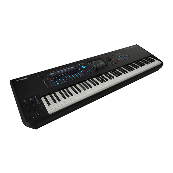
- Page 27 5-34 Ribbon controller Use this controller by running your finger lightly across the surface laterally to control the specific parameter continuously. Or, you can have the parameter change in steps, depending on the setting. Depending on the function you’ve assigned, you can use it as a speed switch for the rotary speaker. Playing the keyboard Keyboard The MONTAGE M6 features a 61-key keyboard, while the MONTAGE M7 has 76 keys and the MONTAGE M8X has 88 keys. All are equipped with a touch response feature (both initial touch and aftertouch). With initial touch, the instrument senses how strongly or softly you play the keys and uses that playing strength to alter the sound in various ways, depending on the selected Performance, Aftertouch, on the other hand, lets you alter the sound by the amount of pressure you apply to a note after playing it. In addition, any of a variety of functions can be assigned to aftertouch for each Part. The sophisticated GEX keyboard for the MONTAGE M8x provides exceptionally delicate expressiveness. Since the instrument has polyphonic aftertouch capability, you can control the aftertouch value individually for each key. MONTAGE M Quick Guide...
-
Page 28: Rear Panel
Rear panel Connecting USB flash drive AC outlet External USB MIDI Computer keyboard [STANDBY/ON] switch Press this switch to set the instrument to On or Standby. [AC IN] jack (power cord socket) Connect the power cord supplied with this instrument. USB TO DEVICE terminals Use these terminals for connecting USB flash drives and USB MIDI keyboards. When a USB flash drive is connected, the terminal lets you save data created on this instrument to the USB flash drive and load data from the USB flash drive to the instrument. Sending and receiving data between the USB flash drive and this instrument can be set from [UTILITY] g Contents g Store/Save (or Load). When a USB MIDI keyboard is connected, you can use it in the same way as the built-in keyboard of this instrument, as far as the connected keyboard’s specifications allow. For more in-formation, refer to the Operation Manual. MONTAGE M Quick Guide... - Page 29 NOTE For more information about the handling of USB devices, refer to the owner’s manual for the USB device. „ Compatible USB devices • USB flash drive • USB MIDI keyboard Other USB devices such as a USB hub, computer keyboard, or mouse cannot be used. The instrument does not necessarily support all commercially available USB devices. Yamaha cannot guarantee the operation of USB devices that you purchase. Before purchasing a USB device for use with this instrument, please visit the following web page: https://download.yamaha.com/ Although USB devices 1.1 to 3.0 can be used on this instrument, the amount of time for saving to or loading from the USB device may differ depending on the type of data or the status of the instrument. NOTICE The rating of the USB TO DEVICE terminal is a maximum of 5 V/500 mA for each terminal. Do not connect USB devices having a rating above this, since this can cause damage to the instrument itself.
- Page 30 FC4, FC3, FC4, External MIDI keyboard MIDI terminals Use this terminal for connecting external MIDI devices. FOOT SWITCH [ASSIGNABLE] jack FOOT SWITCH [SUSTAIN] jack Use these jacks for connecting footswitches and a sustain pedal. FOOT SWITCH [SUSTAIN] is a jack for connecting separately sold foot switches FC3, FC4, and FC5 to use exclusively for sustain. FOOT SWITCH [ASSIGNABLE] jack is a jack for connecting a separately sold FC4 and FC5 for using other functions you assign to the pedal. For example, you can use a footswitch to switch to the next Performance while the Live Set screen is shown. NOTE In this manual, the term “FC3” refers to the FC3 and all other equivalent products, such as the FC3A, and the term “FC4” refers to the FC4 and all other equivalent products, such as the FC4A. FOOT CONTROLLER jacks Use these jacks for connecting a separately sold FC7 Foot Controller. You can assign a function in the Part Edit to control various parameters for the sound, such as its volume and pitch. Jacks and pin alignment Input and Output jacks Polarities Balanced/Unbalanced Connector types 7-10 ASSIGNABLE OUTPUT (BALANCED) Tip: Hot (+) Balanced...
- Page 31 Audio device Headphones Keyboard amplifier Microphone Monitor speakers A/D INPUT jacks Use these standard phone jacks for receiving the audio signals from the external device. By connecting an audio device such as a microphone and CD player, as well as another synthesizer and electronic musical instrument, you can play the sound as an audio input Part. Use the mono standard phone plug for connection. For stereo input using audio equipment, use the [L/MONO] and [R] jacks. For mono input using microphones, use only the [L/MONO] jack. In addition, you can use the Vocoder as an internal effect with this instrument. When using the Vocoder, connect a microphone to the [L/MONO] jack and control the Vocoder by using the audio input from the microphone. You can also use this jack for the Envelope Follower and ABS (Audio Beat Sync) features. For details about the Envelope Follower and ABS features, refer to the Operation Manual. NOTE • A guitar or bass having active pickups can be directly connected. However, when using passive pickups, connect the instrument via an effect device. • The Vocoder/Envelope Follower can be controlled from all Part outputs and not just the A/D INPUT jack. 7-10 ASSIGNABLE OUTPUT (BALANCED) jacks (TRS balanced output) Separate from the OUTPUT jacks, these TRS balanced output jacks are for outputting a specific sound or Part— allowing you to apply external effects or processing for that sound or Part. However, keep in mind that the System effect, Master effect, and Master EQ cannot be applied to the sound output from the ASSIGNABLE OUTPUT jacks. Listed below are the sounds or Parts that can be output individually. • Drum Part keys to which drum/percussion instruments are assigned • Metronome (Click) • Any Part of a Performance* * For more information on the audio input part (AUDIO IN Part), refer to the Operation Manual.
-
Page 32: Setting Up
Setting up Power supply Connect the supplied power cord in the following order. Make sure the [STANDBY/ON] switch on the instrument is set to the Standby position. Connect the supplied power cord to the AC IN Rear panel terminal on the instrument’s rear panel. Connect the other end of the power cord to an AC outlet. [AC IN] jack WARNING Use only the power cord supplied with your instrument. The power cord supplied with your instrument must not be used with any other electrical devices. -
Page 33: Turning The Instrument On
Turning the instrument ON Turning the instrument OFF Make sure the volume settings of the instrument and external devices, such as powered speakers, are turned to the minimum before turning the power on. When connecting the instrument to powered speakers, turn on the power switch of each device in the following order. „ When turning the power on First, the instrument (displays will turn on and buttons will light), and then the connected powered speakers. „ When turning the power off First, the connected powered speakers, and then the instrument (displays will turn off and buttons will turn off). Keep in mind that the [STANDBY/ON] switch is located at [STANDBY/ON] the right side (from the view of the keyboard) of the AC IN switch [AC IN] jack socket on the rear panel of the instrument. WARNING Even when the [STANDBY/ON] switch is in standby status, electricity is still flowing to the product at the minimum level. -
Page 34: Adjusting The Master Volume
Adjusting the master volume Adjust the overall level of this instrument by using the [MASTER VOLUME] knob. Min. Max. CAUTION Do not listen over the headphones at high volume for long periods of time. Doing so may cause hearing loss. First, adjust the master volume on this instrument, and then other volume controls. For more information, refer to the Operation Manual. Panel Lock feature Pressing this button while holding down the [SHIFT] button locks the operations on the controllers on the top panel. While Panel Lock is ON, any operations other than the built-in keyboard, pedals, master volume, super knob, pitch bend wheel, modulation wheel, ribbon controller, and the Panel Lock control itself will be disabled. The operations on the touchscreen will also be disabled. Pressing this button again while holding down the [SHIFT] button unlocks the operations on the controllers on the top panel. Using USB flash drives By connecting a USB flash drive to a USB TO DEVICE terminal, you can save your custom data to the connected drive, as well as read data from it. -
Page 35: Preparation For Live Performance
Preparation for live performance Shown below is a possible way for preparing the MONTAGE M for use in live performance situations. Selecting a Performance from the Live Set screen from the Performance screen Editing the settings Saving edited settings Creating a Live Set Selecting a Performance from a Live Set Playing the keyboard MONTAGE M Quick Guide... -
Page 36: Status Check And Basic Operation
Status check and basic operation You can check the status by looking at the buttons, sliders, and displays on the top panel. By using the data dial and buttons or by tapping the touchscreen, you can switch to a different screen or change settings. Checking the status Shown on the top panel The brightness and the color of the buttons on the top panel indicate the status of the settings. Brightness There are three levels of brightness for the buttons. Brightness Description Full light The function is set to ON. Dim light The function is available but set to OFF. You can press the button to set the function ON. The function is not available and is set to OFF. Nothing occurs when you press the button. Color The color of the slider slits and buttons indicate what they are set to control. Slider slits Color Controls Bright blue Cyan Internal Part Yellow Yellow Elements, drum keys, operators, oscillators Audio Blue Blue Parts in External mode or DAW Remote mode... - Page 37 Main display Below are explanations of the Navigation bar shown on the Main display at all times. Navigation bar 1 2 3 4 5 6 Edit Common Indicators Descriptions The same function as the [PERFORMANCE] button on the top panel. Home Tapping the icon calls up the Performance screen (Home screen). The same function as the [EXIT] button on the top panel. Exit Tapping the icon returns one level up in the hierarchical order. The current screen name and information regarding the Parts, elements, operators, oscillators, and drum keys. Information area By tapping q, you can change the Part, element, operator, oscillator, and drum key. For Normal Parts Status for the elements, operators, and oscil-lators are shown. • Mute: green “M” icon • Solo: red “S” icon Element numbers 1–8 1 2 3 4 5 6 7 8 The element being played is indicated by lights below the numbers.
- Page 38 1 2 3 4 5 6 Edit Common Indicators Descriptions Tempo for the current Performance Tempo setting Tapping the icon calls up the Tempo Setting screen. Live Set Tapping the icon calls up the Live Set screen. Utility Tapping the icon calls up the previous tab on the Utility screen. Navigation button The “map” of the signal flow of this instrument is shown on the screen. By tapping the item on the map you wish to edit, you can call up the corresponding setting screen. Performances and Parts The Performances and the Parts are shown with flags and attributes. Flags are labels that indicate the sound engine types for the Performance or the Part. Flag Descriptions AWM2 Performance consisting only of AWM2 Parts; Part using AWM2. Performance consisting only of FM-X Parts; Part using FM-X. (in 1 color) Performance consisting only of FM-X Parts and Smart Morph; FM-X Part containing Smart Morph. (in 2 colors) AN-X Performance consisting only of AN-X Parts; Part using AN-X. * The Performances that combine multiple sound engine types are expressed using the “+” sign. MONTAGE M Quick Guide...
- Page 39 Attributes are labels used to identify types of Performances or Parts. You can use the attribute to filter search results to see only the Performances or Parts that suit your needs. Attribute Descriptions AWM2 AWM2 sound engine FM-X FM-X sound engine AN-X AN-X sound engine Performance that features Motion Control Performance that supports Seamless Sound Switching Seamless Sound Switching (SSS) is a feature that lets you switch Performances smoothly without any notes being cut off. SSS is available under the conditions stated below. • Parts 9 to 16 are not used Smart Morph Performance with Smart Morph settings Single-Part Performance (Performance containing one Part) Single Use this when you want to play one instrument sound. The Single-Part Performances are shown in green on the Performance Category Search screen. Multi-Part Performance (Performance containing multiple Parts) Multi Use it this when you want to play multiple instruments in layer or split combinations. Multi-Part Performances are shown in blue on the Performance Category Search screen. MOTIF XF Factory Performance for MOTIF XF MONTAGE Factory Performance for MONTAGE MONTAGE M Factory Performance for MONTAGE M MONTAGE M Quick Guide...
-
Page 40: Opening Setting Screens
Opening setting screens When you select a tab on the first column from the left of the touchscreen, and then select a tab on the second column, the parameter edit view appears. In the parameter edit view, you can change the parameter value or switch the settings on or off. Select a tab on the Select a tab on the second Parameter edit view first column column (if available) 1 2 3 4 5 6 7 8 Close the edit view by doing Edit Common one of the following: Main Category Sub Category Performance Name General Perf Piano Acoustic CFX + FM EP / Pitch Settings • Press the [EXIT] button. -
Page 41: Moving The Cursor And Changing Parameter Values
By using the touchscreen Tap the appropriate tab shown on the touchscreen. Moving the cursor and changing parameter values Use the four cursor buttons on the dial ring to move the cursor on the touchscreen in four directions. You can move the cursor by touching the item shown on the touchscreen. Change the parameter value at the cursor position by using the data dial, [INC/YES] button, and [DEC/NO] button. For parameters with large value ranges, you can increase the value by 10 by holding down the [SHIFT] button and pressing the [INC/YES] button. To decrease by 10, hold down the [SHIFT] button and press the [DEC/NO] button. Cursor buttons Data dial Decreases Increases number number By moving a cursor position to a different row of the parameters using the up and down buttons, you can control a different set of parameters using the display knobs 1 2 3 4 5 6 7 8 Edit Common Main Category Sub Category Performance Name General Perf Piano... -
Page 42: Icons Shown For Specific Operations
Icons shown for specific operations Icons Operations The context menu appears. Tap the context menu button to switch to a different screen. Category Search Edit Recall Property Favorite The pop-up list appears. Touch the item that you wish to select from the list. When there are many items, up and To close the pop-up list, you can press the [ENTER] button or the [EXIT] button on down scroll buttons are available. the Top panel or tap outside the pop-up list on the screen. Main Category Piano Keyboard Organ Guitar Bass Strings Brass Woodwind Syn Lead The screen for entering names appears. Tap the icon to call up the screen for entering names. Move to a different screen Tap the icon to call up the confirmation screen for the function. Use the [INC/YES] button or the [DEC/NO] button to confirm the operation. Add a Part Tap the “+” sign to add a Part. MONTAGE M Quick Guide... -
Page 43: Entering Characters And Numbers
Entering characters and numbers Entering characters To enter characters, use the keyboard shown on the screen. The keyboard screen appears when you select the item that requires entering names by tapping the item on the screen or by moving the cursor to the item and pressing the [ENTER] button. Cancel Cancel Performance Name Performance Name CFX + FM EP CFX + FM EP ()” & 123@ Space Done Space Done Delete all characters Cancel all character changes on the screen Switch between upper case and lower case Switch to the keyboard for entering symbols Insert a space at the cursor position (same as the [INC/YES] button) Move the cursor Delete one character (same as using the [DEC/NO] button) Finish entering characters and close the screen Switch to the keyboard for entering alphabetical characters MONTAGE M Quick Guide... - Page 44 Entering numbers For entering numbers, you can use the keys on the built-in keyboard or the numeric pad shown on the screen. One way of entering a number is by pressing a key on the built-in keyboard. This is useful, for example, for entering a note number or velocity value. Another way of entering a number is by using the numeric pad on the screen. This is useful, for example, for specifying the value that requires a numerical entry. By tapping the corresponding item on the screen or by moving the cursor and pressing the [ENTER] button, the following tab appears. 1 2 3 4 5 6 Performance Part 1 Common CFX + FM EP Smart Morph 9-12 13-16 Keyboard CFX + FM EP PlANO PlANO PlANO C -2 Number Mute Solo Home Display Mode TG Note Limit TG Vel Limit...
- Page 45 The Sub display Using the Sub display To change settings shown on the Sub display, use the [QUICK EDIT] button, Knobs 1 to 8, Tab selection buttons, Tab PAGE buttons, and the [ASSIGN] button. View the Sub display Using the Page Jump function To change advanced settings of the parameters shown on the Sub display, use the [PAGE JUMP] button to move to the setting screen on the Main display and then edit the parameter value. After editing, press the [PAGE JUMP] button while holding down the [SHIFT] button so that the edited parameter values are shown on the Sub display. View the Sub display View the Main display MONTAGE M Quick Guide...
-
Page 46: Playing The Keyboard
Playing the keyboard First, select a preset Performance from the Live Set screen and try playing the keyboard. Selecting a Performance from the Live Set screen Press the [LIVE SET] button. The Live Set screen appears. Performance (16 Performance Sets on one page) Live Set Page Bank Preset Best of MONTAGE CFX + FM EP Wax And Wane Pearly Gates DJ Montage A.PIANO CFX+FM EP SYN PAD w/ Auto SK CHILL OUT Style ARP DANCE Style ARP... -
Page 47: Troubleshooting
Troubleshooting No sound? Wrong sound? When these or other problems occur, make sure to check the troubleshooting section in the Operation Manual before assuming that the product is faulty. Many problems can be solved by carrying out the Initialize All Data operation (below), after backing up your data to a USB flash drive. If the problem persists, consult your Yamaha dealer. Restoring the factory default settings (Initialize All Data) NOTICE When the Initialize All Data function is carried out, all the Performances and songs in the User memory you have stored, as well as the Utility settings for the overall keyboard settings will be overwritten with their defaults. -
Page 48: Specifications
Tone Generator Motion Control Synthesis Engine AMW2: 128 Elements (max.) FM-X: 8 Operators, 88 Algorithms AN-X: 3 Oscillators, 1 noise generator Display 7" TFT Color Wide VGA LCD touchscreen, 512 × 64 full-dot LCD Connectivity USB TO DEVICE [1]/[2], [USB TO HOST], MIDI [IN]/[OUT]/[THRU], FOOT CONTROLLER [1]/[2], FOOT SWITCH [SUSTAIN]/[ASSIGNABLE], OUTPUT (BALANCED) [L/MONO]/[R] (6.3 mm, Balanced TRS jacks), ASSIGNABLE OUTPUT (BALANCED) [L]/[R] (6.3 mm, Balanced TRS jacks), [PHONES] (6.3 mm, standard stereo phone jack), A/D INPUT [L/MONO]/[R] (6.3 mm, standard phone jacks) Dimensions, Weight MONTAGE M8x: 1,446 (W) × 460 (D) × 170 (H) mm, 28.1 kg (56-15/16" (W) × 18-1/8" (D) × 6-11/16" (H), 61 lb 15 oz) MONTAGE M7: 1,244 (W) × 396 (D) × 131 (H) mm, 17.6 kg (49-0" (W) × 15-9/16" (D) × 5-3/16" (H), 38 lb 13 oz) MONTAGE M6: 1,037 (W) × 396 (D) × 131 (H) mm, 15.3 kg (40-13/16" (W) × 15-9/16" (D) × 5-3/16" (H), 33 lb 12 oz) Included Accessories Power cord, Quick Guide (this book), Cubase AI download information Expanded Softsynth Plugin for MONTAGE M download information The complete list of specifications is available on the following website. www.yamaha.com/2/montagem * The contents of this manual apply to the latest specifications as of the publishing date. Since specifications, equipment or separately sold accessories may not be the same in every locale, please check with your Yamaha dealer. MONTAGE M Quick Guide... -
Page 49: Index
Index For a convenient index of terms on how to use the instrument, search the Operation Manual (HTML). https://manual.yamaha.com/mi/synth/montage_m/index_q.html AN-X ....................9, 36, 37 Panel Lock feature ................32 attribute ....................37 Part ......................10 Auto Power Off function ..............31 Performance ..................10 AWM2 ................... 9, 36, 37 Preset bank .....................11 bank ......................11 Single-Part Performance ............10, 37 slot ......................11 Soundmondo ..................10... - Page 50 Note on source code distribution For three years after the final factory shipment, you may request from Yamaha the source code for any portions of the product which are licensed under the GNU General Public License or GNU Lesser General Public License by writing to the following address: Digital Musical Instruments Strategy Planning Group, Digital Musical Instruments Development Department Musical Instruments Business Unit, YAMAHA Corporation 10-1 Nakazawa-cho, Naka-ku, Hamamatsu, 430-8650, JAPAN The source code will be provided at no charge; however, we may require you to reimburse Yamaha for the cost of delivering the source code to you. • Note that we shall bear no responsibility whatsoever for any damage arising from changes (additions/deletions) made to the software for this product by a third party other than Yamaha (or party authorized by Yamaha). • Note that re-use of source code released to the public domain by Yamaha is unguaranteed, and Yamaha shall not bear any responsibility whatsoever for the source code. • The source code can be downloaded from the following address: https://download.yamaha.com/sourcecodes/synth/ MONTAGE M Quick Guide...
- Page 51 MEMO...
- Page 52 MEMO...
- Page 53 Important Notice: U.S. LIMITED WARRANTY for Customers in the United States For detailed information about this Yamaha product and warranty service, please either visit the following website address (printable file is available at our website) or contact Customer Service at the address or telephone number identified below. Website Address: Yamaha.io/SynthAndStageWarranty Customer Service: Yamaha Corporation of America 6600 Orangethorpe Avenue, Buena Park, CA 90620-1273 Telephone: 800-854-1569...
- Page 56 © 2022 Yamaha Corporation Published 12/2022 MWMA-A0 VEW4480 10-1 Nakazawa-cho, Naka-ku,Hamamatsu, 430-8650 Japan...
Need help?
Do you have a question about the MONTAGE M6 and is the answer not in the manual?
Questions and answers