Table of Contents
Advertisement
Quick Links
Advertisement
Table of Contents

Related Manuals for Park House Healthcare AMBIENCE


Summary of Contents for Park House Healthcare AMBIENCE
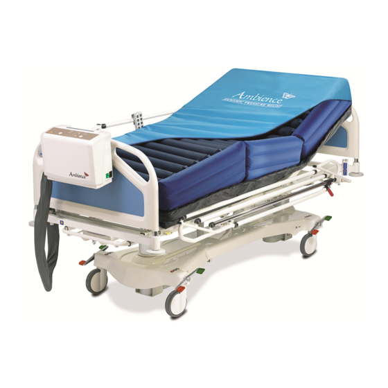
- Page 1 AMBIENCE Low Air Loss Mattress Replacement System Service Manual...
-
Page 2: Table Of Contents
PRODUCT VIEW ILLUSTRATION: ..................2 ........................ 2 RONT ........................ 2 ANEL 1 ........................ 3 IDE VIEW 2 ........................ 3 IDE VIEW ........................4 EAR VIEW ………………………………………………………………………………………………….4 OTTOM SERVICE INSTRUCTION: ....................5 ....................6 LL PART ILLUSTRATION 2 .1 .1 BA SE CAS E AS SE MBLY ……………………………………………………………………… 6 2.1.2 CONTROL PCB……………………………………………………………………………………………7 2.1.3... -
Page 3: Product View Illustration
1 Product View illustration: 1.1 Front View Front View (For AMBIENCE) 1.2 Panel View Panel View (For AMBIENCE) ● On/Off Button ● Low Pressure Key ● High Pressure Key ● Panel Lock Button ● Pressure Level Indicator ● Fowler Boost Indicator ●... -
Page 4: Side View 1
1.3 Side view 1 Side View 1 ● Flower Boost Sensor Pad Connector ● Air outlet (Quick Connector) 1.4 Side view 2 Side View 2 Power switch Power cord socket 2008.01 V1.0... -
Page 5: Ottom Iew
1.5 Rear view Rear View Handle Pump Bumper*4 Mounting Bracket Fuse Box*2 1.6 Bottom view Bottom View Pump Cushion*4 Air Filter 2008.01 V1.0... -
Page 6: Service Instruction
2 Service Instruction: Instruction for all general service repairs Warning Unplug power cord from mains, ensure no electrical current is detected prior repair. Attention: Before commencing the repair please follow instructions indicated from below. For all the required replacement parts, please contact your agent for part number. -
Page 7: All Part Illustration
2.1 All part illustration 2.1.1 AMBIENCE Base Case Assembly A. 120V/60Hz ● Hanger ● Main PCB Assembly ● Blower ● Power PCB ● Connection ● Transformer Tube ● EMI PCB ● Quick Connector ● Power Switch ● Rechargeabl e Battery Fig_2-1a B. -
Page 8: Control Pcb
2.1.2 Control PCB ● Pressure Sensor ● Control Panel ● Pressure Connector Calibrating Circuit ● Rechargeabl Connecting Site e Battery Connector ● CPR Function Detecting ● Connector ● Power PCB Connecting Site ● Fowler Boost Fig_2-2 Fig_2-3 Connector 2.1.3 Power PCB ●... -
Page 9: Emi Pcb
2.1.4 EMI PCB A. 120V/60Hz ● Ground Wire Point ● AC High Voltage Input Point ● AC High Voltage Output Point Fig_2-5a B. 230V/50Hz ● Ground Wire Point ● AC High Voltage Input Point ● AC High Voltage Output Point Fig_2-5b 2008.01 V1.0... -
Page 10: Top Case Assembly
2.1.5 Top Case Assembly ● Control Panel Connector Fig_2-6 2008.01 V1.0... -
Page 11: Pump Assembly Exploded Diagram
2.2 Pump Assembly Exploded Diagram 2.2.1 AMBIENCE Pump Assembly Exploded Diagram/BOM. A.120V/60Hz 2008.01 V1.0... - Page 12 AMBIENCE Pump Assembly BOM – 120V/60Hz Item PART NAME/SPECIFICATION Quantity F600A01-0000 Top case assembly F602A01-0000 Base case assembly 604209-0000 Lead wire 604201-0000 Lead wire, brown 604202-0000 Lead wire, blue 604203-0000 Lead wire, white 664905-0000 Power cord socket 884203-0000 Lead wire, brown...
- Page 13 Screws, M3*8 ㎜ 885013-0000 F375A03-0000 Silicone tube 991812-0000 Zipper tip F609A03-0000 Handle assembly 605005-0000 Screws, M4.0*32mm 662401-0000 Fuse sticker 602401-0000 Specification Sticker 602102-0000 Hanger instruction sticker 604101-0000 Power cord assembly 604301-0000 Power switch 2008.01 V1.0...
- Page 14 B. 230V/50Hz 2008.01 V1.0...
- Page 15 AMBIENCE Pump Assembly BOM – 230V/50Hz ITEM Part Name/Specification Quantity F600A01-0000 Top case assembly F602A01-0000 Base case assembly 604209-0000 Lead wire 604201-0000 Lead wire, brown 604202-0000 Lead wire, blue 604203-0000 Lead wire, white 664905-0000 Power cord socket 884203-0000 Lead wire, brown...
- Page 16 F375A03-0000 Silicone tube 991812-0000 Zipper tip F609A03-0000 Handle assembly 605005-0000 Screws, M4.0*32mm 402401-0000 Fuse sticker 602402-0000 Specification Sticker 602102-0000 Hanger instruction sticker 604102-0000 Power cord assembly 604301-0000 Power switch 604002-0000 Transformer, 230V/50Hz 605501-0000 Spring 604210-0000 Lead wire 2008.01 V1.0...
-
Page 17: Top Case Assembly Exploded Diagram/Bom
2.2.2 Top Case Assembly Exploded Diagram/BOM Top case BOM Item Part Name/Specification Quantity 601001-0000 Top case, ABS., 94V-0 603101-0000 Foam, 94HF-1 604902-0000 Flexible PCB 603401-0000 Cushion, elastomeric 602101-0000 Quick Connector instruction label 2008.01 V1.0... -
Page 18: Base Case Exploded Diagram/Bom
2.2.3 Base Case Exploded Diagram/BOM Base Case BOM Item Part Name/Specification Quantity 601201-0000 Base case, ABS., 94V-0 603102-0000 Foam, 94HF-1 601701-0000 Air filter cap, ABS., 94V-0 603103-0000 Air filter 601702-0000 Air filter cap, ABS., 94V-0 603406-0000 Cushion, elastomeric 603404-0000 Cushion, elastomeric 603401-0000 Cushion, elastomeric 885010-0000... -
Page 19: Handle Exploded Diagram/Bom
2.2.4 Handle Exploded Diagram/BOM Handle BOM Item Part Name/Specification Quantity 605104-0000 Handle 601705-0000 Handle Fixing Pedestal (Left) 605004-0000 Screws, M5*19mm 601707-0000 Handle Fixing Pedestal – Plate (Left) 605003-0000 Washer 601709-0000 Handle Fixing Pedestal - Lock Pin 601706-0000 Handle Fixing Pedestal (Right) 601708-0000 Handle Fixing Pedestal –... -
Page 20: Hanger Exploded Diagram/Bom
2.2.6 Hanger Exploded Diagram/BOM Hanger BOM Item Part Name/Specification Quantity 605301-0000 Hanger 603402-0000 Cushion, NBR 603403-0000 Cushion, NBR 2.2.7 Quick Connector Exploded Diagram/BOM Quick Connector BOM Item Part Name/Specification Quantity 9918C7-0000 Quick Connector (Female Base) Y9918C8-J001 Quick Connector Functional Cap 9918C8-0000 Quick Connector Functional Cap 9918C9-0000... -
Page 21: Blower Exploded Diagram/Bom
2.2.8 Blower Exploded Diagram/BOM – 230V/50Hz Blower BOM Item Part Name/Specification Quantity 554402-0000 Blower 604906-0000 Housing, pitch 6.2mm Connector, ψ2.0 605105-0000 Ferrite Core, ψ18, ψ10, 28mm 604907-0000 2008.01 V1.0... -
Page 22: Pressure Calibration Procedure
2.2.9 Pressure Calibration Procedure Make sure the connector is connected to the pump and rotated to LOCK ON position. STEP-1: Assure the voltage supplied Power Cord from power cord is correct. STEP-2: Switch on the power. The normal power supply light will be illuminated. - Page 23 STEP-5: Enter in the calibration procedure, the Comfort level 1 & 2 LED will light up, while the remaining LED lights should not be lit. STEP-6: Provide a stable 10mmHg pressure. STEP-7: Wait for 5 seconds, then press the Alarm Mute button. After that the Comfort level 9 &...
- Page 24 STEP-9: Wait for 5 seconds, then press the Alarm Mute button. STEP-10: After pressing the Alarm Mute button, the Comfort level 9 & 10 LED will turn off. The On/Off LED light will flash 5 times and then turn off. It means the pressure calibration procedure is now completed.
-
Page 25: Control Panel Testing Sop
2.2.10 Control Panel (Flexible PCB) Testing SOP STEP-1: Assure the position of the connector PIN numbers is correct. Refer to the serial numbers on PCB, the 1-19 connector PIN number is 1, 3, 5, 7, 9, 11, 13, 15, 17 & 19. The 2-20 connector PIN number is 2, 4, 6, 8, 10, 12, 14, 16, 18 &... - Page 26 STEP-5: While pressing the Panel Lock, MaxFirm and Power buttons together, the multi-meter should conduct. STEP-6: Use the black probe contact with PIN 14 position and the red probe contact with PIN 6 position. STEP-7: Press the Comfort Firm, Soft and Alarm Mute buttons together.
-
Page 27: Service
3 Service Resolve problem 1. No power. 2. Control panel has no response within power. 3. Blower is unable to work. 4. Failure of LOCK/ON function on connector 5. Failure of Power Failure Alarm 6. Failure of Maxfirm 7. Fowler Boost Malfunction 2008.01 V1.0... -
Page 28: Power
5. Check if the connecting wire leads between fuses terminal and power switch terminal have been disconnected. 6. Check to see the fuses functioning well (referring AMBIENCE pump assembly exploded diagram in section 2.2.1). If the fuses blown, replace the new one (referring AMBIENCE pump assembly BOM in section 2.2.1). -
Page 29: Blower Is Unable To Work
3.1.3 T3 Blower is unable to work. SOP: 1. Make sure the power output connector connecting securely (referring AMBIENCE pump assembly exploded diagram in section 2.2.1, and 2.1.3 Power PCB diagram). 2. Make sure the blower control connector connecting securely (referring AMBIENCE pump assembly exploded diagram in section 2.2.1, and 2.1.3 Power PCB... -
Page 30: Maxfirm Faulure
2. Repeat the pressure calibration procedure (referring 2.1.2 Control PCB diagram). 3. If the above-mentioned check is normal, we suggest to replace the control PCB (referring AMBIENCE pump assembly exploded diagram/BOM in section 2.2.1). 3.1.7 T7 Fowler Boost Malfunction SOP:... -
Page 31: Tools
4. Tools 4.1 List of Recommended Tools and Equipments Name Philips screwdriver Screwdriver, slotted Multi-meter Hex Socket screwdriver M11 open-ended wrench Pressure meter (0-40mmHg) 2008.01 V1.0... - Page 32 The Company Park House Healthcare is proud to offer a 24 hour telephone help care line 365 days a year with a dedicated one-on-one personal customer service at all times. With distributors in over 35 coun- tries, Park House healthcare are a truly international company and place important emphasis on providing high levels of customer care to ensure we exceed customer expectations at all times.
Need help?
Do you have a question about the AMBIENCE and is the answer not in the manual?
Questions and answers