Table of Contents
Advertisement
Quick Links
Instructions–Parts List
STAINLESS STEEL
Dura–Flo
With Severe-Duty Rod and Cylinder
Part Nos. 253377, Series A 28:1 Ratio, with Quiet King
Air Motor
19.3 MPa, 193 bar (2800 psi) Maximum Fluid Working Pressure
0.7 MPa, 7 bar (100 psi) Maximum Air Input Pressure
Part No. 222897 Pump, Series B,
®
with Viscount
Hydraulic Motor
18 MPa, 179 bar (2600 psi) Maximum Fluid Working Pressure
10 MPa, 103 bar (1500 psi) Maximum Hydraulic Input Pressure
Part Nos. 24Y208, 24Y209‡, 24Y210‡,
24Y221, 24Y222, 24Y225, 24Y226, 24Y227‡,
24Y228‡, Pumps, Series A,
45:1 Ratio, with XL10000
31 MPa, 310 bar (4500 psi) Maximum Fluid Working Pressure
0.7 MPa, 7 bar (100 psi) Maximum Air Input Pressure
‡ Not
nor
Important Safety Instructions
Read all warnings and instructions in this manual.
Save these instructions.
See page 2 for Table of Contents.
1800 Pumps
TM
TM
Air Motor
PROVEN QUALITY. LEADING TECHNOLOGY.
TM
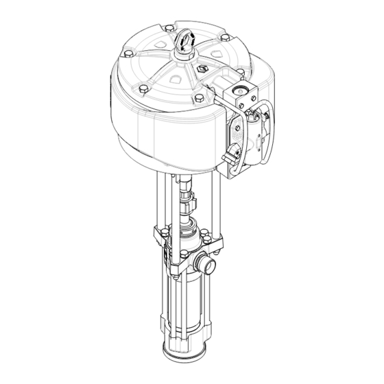
Part No. 24Y192 Shown
308148ZAD
EN
Advertisement
Table of Contents

Subscribe to Our Youtube Channel
Related Manuals for Graco 253377


Summary of Contents for Graco 253377
- Page 1 Dura–Flo 1800 Pumps With Severe-Duty Rod and Cylinder Part Nos. 253377, Series A 28:1 Ratio, with Quiet King Air Motor 19.3 MPa, 193 bar (2800 psi) Maximum Fluid Working Pressure 0.7 MPa, 7 bar (100 psi) Maximum Air Input Pressure Part No.
-
Page 2: Table Of Contents
Required Tools ......17 Graco Information ......38 Disconnecting the Displacement Pump . -
Page 3: Warnings
• Route hoses away from traffic areas, sharp edges, moving parts, and hot surfaces. Do not expose Graco hoses to temperatures above 82º C (180º F) or below –40º C (–40º F). • Wear hearing protection when operating this equipment. - Page 4 Permanently coupled hoses cannot be repaired; replace the entire hose. • Use only Graco approved hoses. Do not remove the spring guard that is used to help protect the hose from rupture caused by kinks or bends near the couplings.
- Page 5 WARNING FIRE AND EXPLOSION HAZARD Improper grounding, poor ventilation, open flames or sparks can cause a hazardous condition and result in a fire or explosion and serious injury. • Ground the equipment and the object being sprayed. Refer to Grounding on page 7. •...
- Page 6 Notes ___________________________________________________________________________________________ ___________________________________________________________________________________________ ___________________________________________________________________________________________ ___________________________________________________________________________________________ ___________________________________________________________________________________________ ___________________________________________________________________________________________ ___________________________________________________________________________________________ ___________________________________________________________________________________________ ___________________________________________________________________________________________ ___________________________________________________________________________________________ ___________________________________________________________________________________________ ___________________________________________________________________________________________ ___________________________________________________________________________________________ ___________________________________________________________________________________________ ___________________________________________________________________________________________ ___________________________________________________________________________________________ ___________________________________________________________________________________________ ___________________________________________________________________________________________ ___________________________________________________________________________________________ ___________________________________________________________________________________________ ___________________________________________________________________________________________ ___________________________________________________________________________________________ 308148...
-
Page 7: Installation
Installation Grounding 7. Object being sprayed: according to your local code. 8. All solvent pails used when flushing, according to WARNING your local code. Use only metal pails, which are conductive, placed on a grounded surface. Do not FIRE AND EXPLOSION HAZARD place the pail on a nonconductive surface, such as Before operating the pump, ground the paper or cardboard, which interrupts the grounding... -
Page 8: Air-Powered Pumps
NOTE: Accessories are available from your Graco distributor. If you supply your own accessories, be sure they are adequately sized and pressure-rated to meet the system’s requirements. - Page 9 Installation (AIR-POWERED PUMPS) SYSTEM ACCESSORIES • An air line lubricator (D) provides automatic air motor lubrication. WARNING • A bleed-type master air valve (E) is required in your system to relieve air trapped between it and the A bleed-type master air valve (E) and a fluid drain air motor when the valve is closed (see the valve (M) are required in your system.
-
Page 10: Hydraulic-Powered Pumps
It is very important to keep the hydraulic supply NOTE: Accessories are available from your Graco system clean at all times. Be sure that all hydraulic distributor. If you supply your own accessories, be sure fluid lines are absolutely clean. - Page 11 TYPICAL INSTALLATION A Pump Airless Spray Gun or Dispensing Valve B Wall Bracket Drum Suction Kit C Hydraulic Supply Line Hydraulic Supply Line Shutoff Valve D Hydraulic Return Line Hydraulic Return Line Shutoff Valve E Drain Line (from pressure reducing valve) Ground Wire (required, see page 7 for F Pressure Gauge installation instructions)
- Page 12 Use a whip hose (P) and a hydraulic fluid. Use only Graco-approved hydraulic oil. swivel (R) between the main fluid hose (N) and the Order Part No. 169236, 5 gal. (19 liter) or 207428, 1 gal.
-
Page 13: Operation/Maintenance
Now clear the tip/nozzle or hose. PACKING NUT/WET-CUP Fill the packing nut/wet-cup (3) 1/3 full with Graco Throat Fig. 6 Seal Liquid (TSL) or compatible solvent. See Fig. 6. Using the supplied wrench (104), adjust the packing nut weekly so it is just snug;... -
Page 14: Air-Powered Pumps
Operation/Maintenance (AIR-POWERED PUMPS) Starting and Adjusting the Pump 6. Use the air regulator to control the pump speed and the fluid pressure. Always use the lowest air pressure necessary to get the desired results. 1. Refer to Fig. 3 on page 8. Connect the suction kit (T) Higher pressures cause premature tip/nozzle and to the pump’s fluid inlet, and place the tube into the pump wear. -
Page 15: Hydraulic-Powered Pumps
Operation/Maintenance (HYDRAULIC-POWERED PUMPS) Starting and Adjusting the Pump 10. Use the fluid pressure gauge (F) and flow control valve (G) to control the pump speed and the fluid 1. Refer to Fig. 5 on page 11. Connect the suction kit outlet pressure. -
Page 16: Troubleshooting Chart
Turn on the air/hydraulic power just enough to start the pump. If the pump starts when the air/hydraulic power is turned on, the obstruction is in the fluid hose or gun. NOTE: If you experience air motor icing, contact your Graco distributor. 308148... -
Page 17: Service
Service REQUIRED TOOLS WARNING • Set of socket wrenches • Set of adjustable wrenches For Model 24Y208 XL10000 Pumps, do not lift the • 24 in. adjustable wrench pump by the lift ring when the total weight exceeds 550 lb (250 kg). •... -
Page 18: Reconnecting The Displacement Pump
Fill the wet-cup (3) 1/3 full of Graco Throat Seal Liquid or compatible solvent. If the rod adapter (102) has loosened during 6. Turn on the air or hydraulic power supply. On maintenance, remove the adapter and apply Loctite®... - Page 19 Service King, Bulldog, and Viscount Pumps XL10000 Pumps (Model 222895 Shown) (Model 24Y192 Shown) Torque to 129–142 N.m (95–105 ft–lb) Torque to 196–210 N.m (145–155 ft–lb) Torque to 312–340 N.m (230–250 ft–lb) Torque to 135–169 N.m (100–125 ft–lb) ® ™ Torque to 192–142 N.m (95–105 ft–lb) Appy Loctite 2760...
-
Page 20: Displacement Pump Service
Service DISPLACEMENT PUMP SERVICE 7. Stand the cylinder (7) upright on a wooden block.Using a rubber mallet or an arbor press, drive Disassembly the displacement rod (1) and piston assembly down into the cylinder as far as possible, then place the When disassembling the pump, lay out all the removed cylinder on its side and continue to drive the rod out parts in sequence, to ease reassembly. - Page 21 Service Included only on standard Displacement Pump Models 222805 and 687055, with stainless steel cap screws (20). Fig. 8 308148...
- Page 22 Service Reassembly 5. Lubricate the o-ring (27*) and seal (6*). Install the o-ring on the intake seat housing (15). Install the 1. If it was necessary to remove the ball guide (9) from intake seat housing (15), intake ball (16), ball guide the displacement rod (1), place the flats of the rod in (14), and seal (6*) in the intake housing (17).
- Page 23 Service Torque to 156–171 N.m (115–126 ft–lb). Torque to 60–74 N.m (45–55 ft–lb). Torque to 459–481 N.m (338–354 ft–lb). Torque oppositely and evenly to 244–264 N.m (180–195 ft–lb). Apply anti-seize lubricant to threads and mating faces. Lubricate. Apply thread lubricant. Use arbor press to drive into cylinder (7).
-
Page 24: Pump Assemblies
Parts Part No. 253377 Pump, Series A Ref. Part No. Description Qty. 28:1 Ratio, with Quiet King Air Motor 235525 AIR MOTOR, King, quiet See 309348 for parts Used on Model 253377 only 102‡ 184451 ADAPTER, connecting rod 103‡ 184096 NUT, coupling 104‡... - Page 25 Parts Part Nos. 24Y208, 24Y209, 24Y210, Ref. Part No. Description Qty. 24Y221, 24Y222, 24Y225, 24Y226, 24Y227, 24Y228, Pumps, Series A, 24Y400 AIR MOTOR, XL10000 334644 for parts 45:1 Ratio, with XL10000 Air Motor 102‡ 184582 ADAPTER, connecting rod 103‡ 184096 NUT, coupling 104‡...
- Page 26 Parts Part No. 222897 Pump, Series B with Ref. Part No. Description Qty. Viscount Hydraulic Motor 235345 HYDRAULIC MOTOR, Viscount, See 308048 for parts 102‡ 184595 ADAPTER, connecting rod 103‡ 184096 NUT, coupling 184278 WRENCH, packing nut 222805 PUMP, displacement See pages 28 &...
- Page 27 Parts NOTE: The parts listed on this page are common to all 184282 GUIDE, ball, intake; stainless steel displacement pumps covered in this manual. The pumps use 222838 HOUSING, seat, intake valve; different packing configurations. Standard Models 222805, stainless steel w/tungsten carbide 241956, 249992, and 687055 use stainless steel cap screws seat with washers.
- Page 28 Parts Throat Packings (see pages 30 (see pages 30 and 32) and 32) Replaces 34 and 35 on 246987, 246988, and 249992) Piston Packings (see pages 30 and 32) 02257 308148...
-
Page 29: Displacement Pumps
Parts Displacement Pumps 222805, 241956, and 687055, Series A (UHMWPE and PTFE Packings, with Stainless Steel Cap Screws) Part Part Description Description 109261 V-PACKING; throat; UHMWPE 184232 GLAND, male; piston; stainless steel 109312 V-PACKING; piston; PTFE 184182 GLAND, female; piston; stainless steel 687057 PACKING;... - Page 30 Parts Displacement Pump 249992, Series A (UHMWPE Submicron and Leather Packings, with Stainless Steel Cap Screws) Part Description 184232 GLAND, male; piston; stainless steel 184182 GLAND, female; piston; stainless steel 109262 V-PACKING; piston; UHMWPE 184181 GLAND, female; throat; stainless steel 109261 V-PACKING;...
-
Page 31: Packing Conversion Kits
Parts Packing Conversion Kits Packing Conversion Kit 222846, (PTFE Max–Life Conversion Kit 288551, Series A Packings) Includes parts to convert existing Dura–Flo 1800 (246987) to Max–Life Displacement THROAT PACKINGS: THROAT PACKINGS: LIPS FACE DOWN LIPS FACE UP Pump 249992. Part Description 15G852 Rod 15G853 Cylinder... -
Page 32: Technical Data
Technical Data (MODELS 222895 AND 253377 KING PUMPS) Ratio ..............28:1 Maximum fluid working pressure . - Page 33 Technical Data (MODELS 222895 AND 253377 KING PUMPS) KEY: Fluid Outlet Pressure – Black Curves 0.63 MPa, 6.3 bar (90 psi) Air Pressure Air Consumption – Gray Curves 0.49 MPa, 4.9 bar (70 psi) Air Pressure 0.28 MPa, 2.8 bar (40 psi) Air Pressure...
- Page 34 Technical Data (MODELS 24Y208, 24Y209, 24Y210, 24Y221, 24Y222, 24Y225, 24Y226, 24Y227, 24Y228, and 249992 XL10000 PUMPS) Ratio ..............47:1 Maximum fluid working pressure .
- Page 35 Technical Data (MODEL 222897 VISCOUNT PUMP) Maximum fluid working pressure ......18 MPa, 179 bar (2600 psi) Maximum hydraulic oil input pressure .
-
Page 36: Dimensions
Dimensions Model 222895 Shown Pump Model 222895, 253377 1235.1 mm (48.63 in.) 642.6 mm (25.3 in.) 592.5 mm (23.33 in.) 298.0 mm (11.73 in.) 24Y208, 24Y209, 1125.0 mm (44.3 in.) 759.0 mm (29.9 in.) 366.0 mm (14.41 in.) 413.0 mm (16.3 in.) -
Page 37: Mounting Hole Layouts
Mounting Hole Layouts King, Bulldog, and Viscount Pumps 94.28 mm (3.712 in.) 101.6 mm 94.28 mm (4.0 in.) (3.712 in.) 50.8 mm (2.0 in.) 11.1 mm (0.437 in.) 88 mm DIA (4) (3.464 in.) XL10000 Pumps 6.186 in. (157.12 mm) (4) 3/8-16 Mounting Holes 8.75 in. -
Page 38: Warranty
With the exception of any special, extended, or limited warranty published by Graco, Graco will, for a period of twelve months from the date of sale, repair or replace any part of the equipment determined by Graco to be defective.
Need help?
Do you have a question about the 253377 and is the answer not in the manual?
Questions and answers