Table of Contents
Advertisement
Quick Links
INSTRUCTIONS-PARTS LIST
This manual contains important
warnings and information.
READ AND KEEP FOR REFERENCE.
INSTRUCTIONS
CARBON STEEL
Dura-Flot 1800 Pumps
With Severe-Duty Rod and Cylinder
Part No. 222–831 Pump, Series A,
14:1 Ratio, with Bulldogr Air Motor
10 MPa, 97 bar (1400 psi) Maximum Fluid Working Pressure
7 bar (100 psi) Maximum Air Input Pressure
Part No. 222–890 Pump, Series A,
14:1 Ratio, with Quiet Bulldogr Air Motor
10 bar, 97 bar (1400 psi) Maximum Fluid Working Pressure
7 bar (100 psi) Maximum Air Input Pressure
Part No. 222–837 Pump, Series A,
28:1 Ratio, with Kingt Air Motor
17 MPa, 174 bar (2520 psi) Maximum Fluid Working Pressure
0.6 MPa, 6.2 bar (90 psi) Maximum Air Input Pressure
Part No. 222–891 Pump, Series A,
28:1 Ratio, with Quiet Kingt Air Motor
17 MPa, 174 bar (2520 psi) Maximum Fluid Working Pressure
0.6 MPa, 6.2 bar (90 psi) Maximum Air Input Pressure
Part No. 237–555 Pump, Series B,
45:1 Ratio, with Premiert Air Motor
31 MPa, 310 bar (4500 psi) Maximum Fluid Working Pressure
7 bar (100 psi) Maximum Air Input Pressure
Part No. 222–892 Pump, Series B,
with Viscountr Hydraulic Motor
18 MPa, 179 bar (2600 psi) Maximum Fluid Working Pressure
10 MPa, 103 bar (1500 psi) Maximum Hydraulic Input Pressure
Refer to page 2 for Table of Contents.
GRACO INC. P.O. BOX 1441 MINNEAPOLIS, MN 55440–1441
http://www.graco.com
ECOPYRIGHT 1991, GRACO INC.
Graco Inc. is registered to I.S. EN ISO 9001
308–147
First choice when
quality counts. t
This manual contains
changes not included
throughout the contents.
Please see the second
page of this book (page 1A)
for a description of the
revisions and additions.
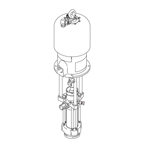
Part No. 222–837 Shown
Rev. N
0566C
Advertisement
Table of Contents

Subscribe to Our Youtube Channel
Related Manuals for Graco 222-831


Summary of Contents for Graco 222-831
- Page 1 10 MPa, 103 bar (1500 psi) Maximum Hydraulic Input Pressure Refer to page 2 for Table of Contents. Part No. 222–837 Shown GRACO INC. P.O. BOX 1441 MINNEAPOLIS, MN 55440–1441 0566C http://www.graco.com ECOPYRIGHT 1991, GRACO INC. Graco Inc. is registered to I.S. EN ISO 9001...
- Page 2 Instruction Manual – Parts List Changes This page contains a summary of changes or additions that do not appear in the contents of the manual. ECO V5814: On pages 1, 20, and 27, Models 222831 and 222890 are obsolete and are removed from the manual. ECO V6253: On page 22, add Model 241490 45:1 ratio Premier Pump to the manual.
- Page 3 Notes 308147...
-
Page 4: Warning Symbol
D This equipment is for professional use only. D Read all instruction manuals, tags, and labels before operating the equipment. D Use the equipment only for its intended purpose. If you are not sure, call your Graco distributor. D Do not alter or modify this equipment. - Page 5 WARNING INJECTION HAZARD Spray from the gun, leaks or ruptured components can inject fluid into your body and cause extremely serious injury, including the need for amputation. Fluid splashed in the eyes or on the skin can also cause serious injury. D Fluid injected into the skin might look like just a cut, but it is a serious injury.
-
Page 6: Fire And Explosion Hazard
WARNING FIRE AND EXPLOSION HAZARD Improper grounding, poor ventilation, open flames or sparks can cause a hazardous condition and result in a fire or explosion and serious injury. D Ground the equipment and the object being sprayed. Refer to Grounding on page 5. D If there is any static sparking or you feel an electric shock while using this equipment, stop spray- ing immediately. -
Page 7: Installation
Installation (ALL PUMPS) Grounding 1. Pump: use a ground wire and clamp. See Fig. 1. Loosen the grounding lug locknut (W) and washer (X). Insert one end of a 1.5 mm@ (12 ga) minimum ground wire (Y) into the slot in lug (Z) WARNING and tighten the locknut securely. -
Page 8: Typical Installation
(105) to the Premier air motor Fig. 2 is only a guide for selecting and installing sys- (101) as instructed on page 14. tem components and accessories. Contact your Graco distributor for assistance in designing a system to suit your particular needs. -
Page 9: System Accessories
Installation (AIR-POWERED PUMPS) SYSTEM ACCESSORIES An air line lubricator (D) provides automatic air motor lubrication. WARNING A bleed-type master air valve (E) is required in your system to relieve air trapped between it and A bleed-type master air valve (E) and a fluid drain the air motor when the valve is closed (see the valve (M) are required in your system. - Page 10 It is very important to keep the hydraulic supply system clean at all times. Be sure that all hydraulic NOTE: Accessories are available from your Graco fluid lines are absolutely clean. Blow out the lines distributor. If you supply your own accessories, be sure...
-
Page 11: Hydraulic Lines
Carefully follow the manufacturer’s recommendations Fluid Line Accessories on reservoir and filter cleaning, and periodic changes of hydraulic fluid. Use only Graco-approved hydraulic Install the following accessories in the positions shown oil. Order Part No. 169–236, 5 gal. (19 liter) or in Fig. -
Page 12: Pressure Relief Procedure
Operation/Maintenance (ALL PUMPS) Pressure Relief Procedure Packing Nut/Wet–Cup Fill the packing nut/wet-cup (3) 1/3 full with Graco WARNING Throat Seal Liquid (TSL) or compatible solvent. See Fig. 4. Using the supplied wrench (104), adjust the packing nut weekly so it is just snug; do not overtigh- INJECTION HAZARD ten. - Page 13 Operation/Maintenance (AIR-POWERED PUMPS) Starting and Adjusting the Pump 6. Use the air regulator to control the pump speed and the fluid pressure. Always use the lowest air pressure necessary to get the desired results. 1. Refer to Fig. 2 on page 6. Connect the suction kit Higher pressures cause premature tip/nozzle and (T) to the pump’s fluid inlet, and place the tube into pump wear.
- Page 14 Operation/Maintenance (HYDRAULIC-POWERED PUMPS) Starting and Adjusting the Pump WARNING 1. Refer to Fig. 3 on page 8. Connect the suction kit COMPONENT RUPTURE HAZARD (T) to the pump’s fluid inlet, and place the tube into To reduce the risk of overpressurizing the fluid supply.
-
Page 15: Troubleshooting Chart
Troubleshooting Chart 1. Relieve the pressure. WARNING 2. Check all possible causes and problems before To reduce the risk of serious injury whenever you disassembling the pump. are instructed to relieve pressure, always follow the Pressure Relief Procedure on page 10. PROBLEM CAUSE SOLUTION... -
Page 16: Required Tools
Fill the wet-cup (3) 1/3 full of support the displacement pump while it is being Graco Throat Seal Liquid or compatible solvent. disconnected, to prevent it from falling and causing 9. Turn on the air or hydraulic power supply. On injury or property damage. - Page 17 Service King, Bulldog, and Viscount Pumps Premier Pumps (Model 222–837 Shown) (Model 237–555 Shown) 0567C 01397C Torque to 129–142 N.m (95–105 ft–lb) Torque to 196–210 N.m (145–155 ft–lb) Torque to 312–340 N.m (230–250 ft–lb) Torque to 135–169 N.m (100–125 ft–lb) Torque to 129–142 N.m (95–105 ft–lb) Torque to 318–349 N.m (234–257 ft–lb) Square hole is for use with torque wrench.
-
Page 18: Displacement Pump Service
Service DISPLACEMENT PUMP SERVICE 7. Stand the cylinder (7) upright on a wooden block. Using a rubber mallet or an arbor press, drive the Disassembly displacement rod (1) and piston assembly down into the cylinder as far as possible, then place the cylinder on its side and continue to drive the rod When disassembling the pump, lay out all the removed out the bottom until the piston comes free. - Page 19 Service 0421B Fig. 6 308-147...
- Page 20 Service Reassembly 5. Lubricate the o-ring (27*) and seal (6*). Install the o-ring on the intake seat housing (15). Install the 1. If it was necessary to remove the ball guide (9) intake seat housing (15), intake ball (16), ball guide from the displacement rod (1), place the flats of (14), and seal (6*) in the intake housing (17).
- Page 21 Service Torque to 156–171 N.m (115–126 ft–lb). Torque to 135–169 N.m (100–125 ft–lb). Torque to 459–481 N.m (338–354 ft–lb). Torque oppositely and evenly to 244–264 N.m (180–195 ft–lb). Apply anti-seize lubricant to threads and mating faces. Lubricate. Apply thread lubricant. Use arbor press to drive into cylinder (7).
- Page 22 Parts Part No. 222–831 Pump, Series A Part No. 222–890 Pump, Series A 14:1 Ratio, with Bulldog Air Motor 14:1 Ratio, with Quiet Bulldog Air Motor 102} 102} 108} 108} 103} 103} }107 }107 }106 }106 0571C 0570C Ref. Ref. Part No.
- Page 23 Parts Part No. 222–837 Pump, Series A Part No. 222–891 Pump, Series A 28:1 Ratio, with King Air Motor 28:1 Ratio, with Quiet King Air Motor 102} 102} 108} 108} 103} 103} }107 }107 }106 }106 0567C 0568C Ref. Ref. Part No.
- Page 24 Parts Part No. 237–555 Pump, Series B Part No. 222–892 Pump, Series B 45:1 Ratio, with Premier Air Motor with Viscount Hydraulic Motor 102} 102} 108} 108} 103} 103} }107 }107 }106 }106 0569BC 01397C Ref. Ref. Part No. Description Qty.
- Page 25 Parts NOTE: The parts listed on this page are common to all Part displacement pumps covered in this manual. The pumps use Description different packing configurations. Standard Model 222–805 uses stainless steel cap screws with washers. Optional 184–276 ROD, displacement; stainless steel pumps use carbon steel cap screws without a washer.
- Page 26 Parts Standard Displacement Pump PTFE Displacement Pump 222–796, Series A ( r and Leather Packings) Part THROAT PACKINGS: PISTON PACKINGS: LIPS FACE DOWN LIPS FACE UP Description 184–232 GLAND, male; piston; stainless steel 184–312 V-PACKING; piston; leather 184–181 GLAND, female; throat; stainless steel 1 PTFE 109–311 V-PACKING;...
-
Page 27: Packing Conversion Kits
Packing Conversion Kits Packing Conversion Kit 222–845, Packing Conversion Kit 222–848, PTFE (UHMWPE and r Packings) (UHMWPE and Leather Packings) THROAT PACKINGS: PISTON PACKINGS: THROAT PACKINGS: PISTON PACKINGS: LIPS FACE DOWN LIPS FACE UP LIPS FACE DOWN LIPS FACE UP 0805 0805 LUBRICATE PACKINGS... -
Page 28: Technical Data
Technical Data Sound Level Data* Pump Model Air Pressure Cycle Rate Sound Pressure Level Sound Power level 222–831 100 psi 25 cycles/min 94 dBa 109 dBa 222–890 100 psi 25 cycles/min 84.7 dBa 99.4 dBa 222–837 90 psi 25 cycles/min 98 dBa 113 dBa 222–891... - Page 29 Technical Data (MODEL 222–831 AND 222–890 BULLDOG PUMPS) WARNING Be sure that all fluids and solvents used are chemically compatible with the Wetted Parts listed below. Always read the manufacturer’s literature before us- ing fluid or solvent in this pump. Ratio .
- Page 30 Technical Data (MODEL 222–837 AND 222–891 KING PUMPS) WARNING Be sure that all fluids and solvents used are chemically compatible with the Wetted Parts listed below. Always read the manufacturer’s literature before us- ing fluid or solvent in this pump. Ratio .
- Page 31 Technical Data (MODEL 237–555 PREMIER PUMP) WARNING Be sure that all fluids and solvents used are chemically compatible with the Wetted Parts listed below. Always read the manufacturer’s literature before us- ing fluid or solvent in this pump. Ratio ............... 45:1 Maximum fluid working pressure .
- Page 32 Technical Data (MODEL 222–892 VISCOUNT PUMP) WARNING Be sure that all fluids and solvents used are chemically compatible with the Wetted Parts listed below. Always read the manufacturer’s literature before us- ing fluid or solvent in this pump. Maximum fluid working pressure .
- Page 33 Dimensions Model 222–837 Shown 0566 Pump Model 222–831 1183.1 mm (46.58 in.) 642.6 mm (25.3 in.) 540.5 mm (21.28 in.) 298.0 mm (11.73 in.) 222–890 1198.6 mm (47.19 in.) 642.6 mm (25.3 in.) 556.0 mm (21.89 in.) 298.0 mm (11.73 in.) 222–837 1225.6 mm (48.25 in.) 642.6 mm (25.3 in.)
-
Page 34: Mounting Hole Layouts
Mounting Hole Layouts King, Bulldog, and Viscount Pumps 94.28 mm (3.712”) 101.6 mm 94.28 mm (4.0”) (3.712”) 50.8 mm (2.0”) 11.1 mm (0.437”) DIA (4) 88 mm (3.464”) 0653 Premier Pumps 135.0 mm 67.5 mm (5.3 in.) (2.7 in.) 116.9 mm (4.6 in.) 87.9 mm (3.5 in.) Three M16 x Holes... - Page 35 Notes 308-147...
- Page 36 Notes 308-147...
- Page 37 Notes 308-147...
-
Page 38: Graco Standard Warranty
Graco distributor to the original purchaser for use. With the exception of any special, extended, or limited warranty published by Graco, Graco will, for a period of twelve months from the date of sale, repair or replace any part of the equipment determined by Graco to be defective.
Need help?
Do you have a question about the 222-831 and is the answer not in the manual?
Questions and answers