Sign In
Upload
Download
Table of Contents
Contents
Add to my manuals
Delete from my manuals
Share
URL of this page:
HTML Link:
Bookmark this page
Add
Manual will be automatically added to "My Manuals"
Print this page
×
Bookmark added
×
Added to my manuals
Manuals
Brands
EM Acoustics Manuals
Amplifier
Di06
Product user manual
EM Acoustics Di06 Product User Manual
Advanced installation amplifier
Hide thumbs
1
Table Of Contents
2
3
4
5
6
7
8
9
10
11
12
13
14
15
16
17
18
19
20
21
22
23
24
25
26
27
28
29
30
31
32
33
34
35
36
37
38
39
40
41
42
43
page
of
43
Go
/
43
Contents
Table of Contents
Troubleshooting
Bookmarks
Table of Contents
Table of Contents
Important Safety Instructions
Consignes de Sécurité Importantes
Compliance
For Customers in Europe
For Customers in the Usa
For Customers in the Canada
Thanks and Unpacking
Unpacking the DI Series Amplifier
Installation Instructions
Mechanical Installation
AC Power Connection
Introduction and Key Features
Introduction
Key Features
Audio Connections
Input Connections
Using Unbalanced Connections
Amplifier Output Connections
Load Matching
Panel Layouts
Operation
Starting up the Unit
Overview of Modules, Presets Components and Snapshots
Drive Module Presets
Component Presets
Factory Module Presets
Storing Module Presets
Recalling Module Presets
Recalling Components
Input
AES3 Inputs
Networked Audio (Dante) Inputs
Automatic Input Selection (Fallover)
Gain and Polarity
Delay
High Pass Filter
Parametric Equalisation
FIR Shelving EQ
Parametric Filters
Routing
Output
Gain and Polarity
Delay
High and Low Pass Filters
LIR Crossover Filtering
Parametric Equalisation and All-Pass Filters
Limiters
Bridge
Routing
Stereo Linking
IP Address
Store Snapshot
Eco
External Breaker Protection (EBP)
Ethernet
Ethernet Configurations
Dhcp
Auto-Ip
Static-IP
IP Troubleshooting
Snapshots
AUX Port a
Fault Relay a
AUX Port B
Check Relay B
AUX Port C
Rs232/ Rs485
Latency Delay
Input/Output Latencies
Processing Latencies
Overlay Flush
Revert to Factory Settings
Protection Systems
Summary of Protection Indication
Incident Reporting
Performance Logging
Tipi Third Party Interface
Processing Block Diagram
EQ and Filter Response Graphs
Technical Specifications
General
Audio
Digital Processing
Power Output
Power Supply
Protection Systems
System Protection
Power Distribution Protection Systems
Monitoring and Logging
Physical
Options
Advertisement
Quick Links
Download this manual
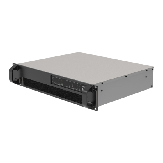
Di06 / Di10 / Di20
advanced installation amplifier
Product User Manual
v1 July 2023
l i b e r a t i n g a u d i o
Table of
Contents
Previous
Page
Next
Page
1
2
3
4
5
Advertisement
Table of Contents
Need help?
Do you have a question about the Di06 and is the answer not in the manual?
Ask a question
Questions and answers
Related Manuals for EM Acoustics Di06
Amplifier EM Acoustics DQ Series User Manual
Advanced system amplifiers (49 pages)
Amplifier EM Acoustics DQ10 Product User Manual
Advanced system amplifiers (49 pages)
Amplifier EM Acoustics Di10 Product User Manual
Advanced installation amplifier (43 pages)
Amplifier EM Acoustics Di20 Product User Manual
Advanced installation amplifier (43 pages)
Amplifier EM Acoustics AQ-3 User Manual
(19 pages)
Amplifier EM Acoustics AD-9 User Manual
(20 pages)
This manual is also suitable for:
Di10
Di20
Table of Contents
Print
Rename the bookmark
Delete bookmark?
Delete from my manuals?
Login
Sign In
OR
Sign in with Facebook
Sign in with Google
Upload manual
Upload from disk
Upload from URL


Need help?
Do you have a question about the Di06 and is the answer not in the manual?
Questions and answers