
Related Manuals for EM Acoustics DQ10


Summary of Contents for EM Acoustics DQ10
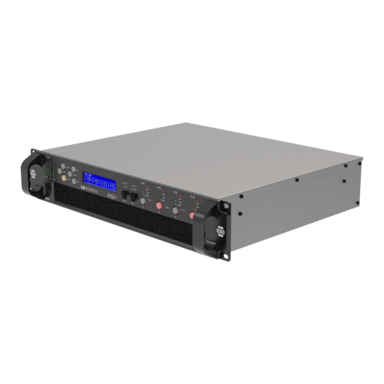
- Page 1 DQ Series DQ6 : DQ10 : DQ20 Advanced System Amplifiers Product User Manual V1.1 April 2024 (For firmware version 1.258 and above) l i b e r a t i n g a u d i o...
-
Page 2: Table Of Contents
Contents IMPORTANT SAFETY INSTRUCTIONS ......................5 CONSIGNES DE SÉCURITÉ IMPORTANTES ....................6 COMPLIANCE .................................8 FOR CUSTOMERS IN EUROPE ..........................8 FOR CUSTOMERS IN THE USA.........................9 FOR CUSTOMERS IN CANADA ........................10 Thanks and Unpacking ............................11 Unpacking the DQ Series Amplifier ......................11 INSTALLATION INSTRUCTIONS ........................ - Page 3 Input ................................27 AES3 Inputs ..............................27 Networked Audio (Dante) Inputs ......................27 Automatic Input Selection (Fallover) ...................... 28 Gain and Polarity ............................28 Delay ................................28 High Pass Filter ............................28 Parametric Equalisation ..........................29 FIR Shelving EQ ............................29 Parametric Filters ............................
- Page 4 AUTO-IP ..............................34 Static-IP ..............................34 IP Troubleshooting ............................ 35 Snapshots ............................... 35 AUX Port ................................. 35 Latency delay ..............................36 Input/Output Latencies ..........................36 Processing Latencies ..........................37 Secure Mode ..............................37 Overlay Flush ..............................38 Revert to Factory Settings ........................... 38 Protection Systems ............................
-
Page 5: Important Safety Instructions
IMP OR T ANT SAF ET Y INSTR UCT IONS Read these instructions. Keep these instructions. Heed all warnings. Follow all instructions. Do not use this apparatus near water. Clean only with dry cloth. Do not block any ventilation openings. Install in accordance with the manufacturer's instructions. -
Page 6: Consignes De Sécurité Importantes
CONSIGNES DE SÉCURITÉ IMPORTANTES 1. Lisez ces instructions. 2. Conservez ces instructions. 3. Respectez tous les avertissements. 4. Suivez toutes les instructions. 5. Ne pas utiliser cet appareil près de l'eau. 6. Nettoyer uniquement avec un chiffon sec. 7. Ne pas bloquer les ouvertures de ventilation. Installer conformément aux instructions du fabricant. - Page 7 AVERTISSEMENT DE SECURITE Ne retirez pas les couvercles, ne desserrez pas les fixations et ne laissez aucune pièce s'introduire dans les ouvertures. AVERTISSEMENT DE SECURITE Le radiateur arrière de cet appareil devient chaud. Evitez tout contact direct avec la peau pendant le fonctionnement et au moins 5 minutes après la mise hors tension de l'appareil.
-
Page 8: Compliance
COMPLIANCE FOR CUSTOMERS IN EUROPE This product complies with both the LVD (electrical safety) 73/23/EEC and EMC (electromagnetic compatibility) 89/336/EEC directives issues by the commission of the European community. Compliance with these directives implies conformity with the following European standards: EN60065 Product safety EN55103-1 EMC emissions... -
Page 9: For Customers In The Usa
DECLARATION OF CONFORMITY WITH FCC RULES We, Instigate Media Ltd (EM Acoustics), of Building 19.11 Dunsfold Park, Cranleigh, Surrey, GU6 8TB, England, declare under our sole responsibility that this family of devices, complies with Part 15 of the FCC Rules. -
Page 10: For Customers In Canada
FOR CUSTOMERS IN CANADA This product complies with CA /CSA C22.2 No.60065-03 Ce produit est conforme avec CA /CSA C22.2 No.60065-03 THIS PRODUCT MUST BE EARTHED. Use only a flexible cable or cord with a green or green / yellow core which must be connected to the protective earthing terminal of a suitable mains plug or the earthing terminal of the installation. -
Page 11: Thanks And Unpacking
All EM Acoustics products are carefully engineered for world-class performance and reliability. If you would like further information about this or any other EM Acoustics product, please contact us. We look forward to helping you in the near future. -
Page 12: Installation Instructions
INSTALLATION INSTRUCTIONS Mechanical Installation The DQ Series amplifiers are designed to be mounted in a standard 19” rack enclosure. Where the amplifier is used in a fixed installation, as long as the bottom unit is supported and there are no gaps between units, it is acceptable to use only the front panel 19” rack holes when fitting it in a standard rack enclosure. -
Page 13: Ac Power Connection
supported with a rear rack mounting kit (part number ZA1182). Damage caused by insufficient support is not covered by the warranty. To prevent damage to the front panel it is recommended that plastic cups or washers are fitted underneath the rack mounting bolt heads. It is possible to mount multiple DQ Series amplifiers without ventilation gaps between them but it is essential that an unobstructed flow of clean air is available from the front of the unit to the rear. -
Page 14: The User Guide
The User Guide This user manual gives a progressively more detailed description of the functions of the EM Acoustics DQ Series Advanced System Amplifiers. A single page quick reference guide is provided for those users who are experienced with this type of equipment and just need to know how to ‘drive’ the front panel. -
Page 15: Introduction And Key Features
Introduction and Key Features Introduction The EM Acoustics DQ Series Advanced System Amplifiers represent current state-of-the-art technology in several areas. This product is the result of several years of research, from which many advances in switched mode power technologies and ever finer detail in signal processing have stemmed. -
Page 16: Drive Modules
Drive Module Preset (i.e. any driver in a loudspeaker subsystem). Being as the majority of EM Acoustics’ systems are passive, and only require one amplifier channel, the Component presets are used widely – see later in this manual for more detail. -
Page 17: Fir Linear Phase Equalisation
The shape of the LIR crossover filter is quite similar to a 4 order or 24dB/Oct Linkwitz-Riley filter, and maintains zero phase difference between the adjacent bands across the crossover region to keep the polar response rock steady. FIR Linear Phase Equalisation The Input High-Shelf Equalisers use Finite Impulse Response (FIR) filtering to produce Linear Phase equalisation;... -
Page 18: Audio Connections
Audio Connections Input Connections For each input channel there is a female XLR connector for analogue inputs. There is also one female XLR for one stream (two channels) of AES3 digital audio. Note that only two channels of AES3 digital audio are available. -
Page 19: Amplifier Output Connections
Amplifier Output Connections The DQ Series amplifiers are fitted with one Speakon connector per amplifier channel. The appropriate conductor terminations are shown below and on the rear panel of the unit. Amplifier output connections – 44M Amplifier output connections – DQ Series Speaker - Speaker + Additionally, the channel 2 output is duplicated on the Speakon... -
Page 20: Load Matching
This very useful feature allows the DQ6 and DQ10 amplifiers to drive more power into single loudspeakers, meaning that even models like EMS-126 and EMS-129 loudspeakers can be driven from... -
Page 21: Panel Layouts
Panel Layouts 1. Input Signal Indicators- A set of five indicators show “Sig”, “-12”, “0dBu”, “+6” and “+12” and “Clip (mute)” for each of the DSP inputs “A” “B” “C” “D”. The signal present Indicators operate at approximately –40 dBu. The Clip/mute Indicators warn the user of input overload and operate at 1dB before clip. - Page 22 Relay output- This isolated relay output may be used to indicate abnormal conditions to external monitoring apparatus. See Fault Relay Power Inlet- The unit should be connected to a suitable mains electricity supply using an earthed Powercon connection power lead. The device has a switch mode power supply that is capable of operating with a nominal mains voltage of 100V to 230V, 50/60Hz without re-configuration.
-
Page 23: Operation
Operation Starting up the unit When power switch is switched on the unit will go through its start-up cycle, checking all the sub- systems as it does so. Along the way, the screen will inform you of its progress. Once this is complete the display will then show the Home screen indicating drive module configurations. -
Page 24: Navigation
Snapshot is a device-wide representation of most of the settings in the device. This is represented as four Input Component numbers, four Output Component numbers, plus a number of machine- centric settings such as routing and Input/Output Analogue/Digital selection etc. Input A component number Output 1 component number Input B component number... -
Page 25: The Home Page
AES3 or networked audio feeds, can drive any number of DSP inputs. Component Presets A Component Preset represents the processing for just one output. Due to EM Acoustics’ product predominantly requiring only one amplifier channel, we use Component presets more frequently than Module presets. -
Page 26: Factory Module Presets
Factory Module Presets Factory Presets The DQ Series device contains a library of designed to suit the EM Acoustics range. Factory Presets contain some parameters that are fixed and hidden from view; these are those parameters that are critical for the correct operation of the loudspeaker, such as high/low pass filters Factory Presets and limiters. -
Page 27: Recalling Components
To recall a Drive Module preset, press the <INPUT> button, then use the down <> button navigate to the RECL Preset page. Using the “ADJUST” encoder will scroll through the presets available. When the desired preset is reached, pressing <ENTER> will display the message “Enter to confirm or to exit”, pressing <ENTER>... -
Page 28: Automatic Input Selection (Fallover)
the connection on the rear of the Device, and set the relevant Input Type menu Type parameter to “Dante” (for example.) When the Digital Audio Network input is installed and routed, the “Net Audio” indicator above the encoders will illuminate. This indicator will come on even if there are no cables plugged into the networked audio port on the Device. -
Page 29: Parametric Equalisation
The Hardman type filter is always described by its order as the filter becomes progressively steeper rather than following a linear slope so a dB/octave description is not accurate. Parametric Equalisation There are nine stages of equalisation available for each input channel, three shelving filters and six parametric filters. -
Page 30: Delay
Delay The delay page controls the amount of delay associated with the output channel selected and is adjustable from 0 to 998ms. The delay parameter is adjustable in fine steps at low values; the adjustment becomes progressively coarser as the value increases. High and Low pass Filters High pass and low pass crossover filtering is provided for the output signal. -
Page 31: Limiters
Please note that whilst the Limiters in this product offer protection for amplifiers and drivers, they can never protect from all possible scenarios, therefore EM Acoustics is not responsible for any damage which might occur. -
Page 32: Bridge
low-frequency response, effectively limiting the linear excursion to below the X-max specification of the driver. To set the limiter up, it is necessary to know the shape of the family of Excursion vs. Frequency curves of the driver for various drive voltage levels. A curve should then be chosen where the slope is high where it passes though the specified X-Max value for the driver. -
Page 33: Stereo Linking
Stereo Linking Stereo linking is available between DSP Drive Modules A & B and between C & D. Changing a parameter in either of the stereo linked Drive Modules will change the other linked Drive Module. Stereo linking is controlled by the STEREO page in the “UTILITY” menu. Note: Stereo linking will only work when the linked Drive Modules are of equal size. -
Page 34: External Breaker Protection (Ebp)
however as there is no negative consequence to doing this since ‘wake-up’ on detecting the presence of an audio input signal is instantaneous. The Standby Now ‘parameter’ allows the amplifier to be put into standby mode manually when it is not being used. -
Page 35: Ip Troubleshooting
IP Troubleshooting If System Engineer cannot connect to the device: • A Router acting as a DHCP server is highly recommended as this provides the most trouble- free way of administering IP addresses. Always switch on any DHCP server before connecting either the computer or Amplifier to the network. -
Page 36: Latency Delay
• 3 Snaps (Event or State) – Either Snapshot 1 or 2 or 3 may be recalled by applying a momentary static connection pattern to an Aux port terminals static • 4 Snaps (State) – One of the four Snapshots 1,2,3,4 may be selected by applying a connection pattern to the Aux port terminals •... -
Page 37: Processing Latencies
Dante Output 0.5ms (TBC) Processing Latencies (limited to a minimum of 1.53ms): Input HiShelf FIR 0.48ms (0ms if set to ‘Off’) LIR Linear Phase crossover 1.19ms/Fhp(kHz), limited to 30ms maximum ** VxLim Limiter (VX mode off) 0.12ms/Fhp(kHz), limited to 1.53ms maximum ** VxLim Limiter (VX mode on) 0.358ms/Fsplit(kHz), limited to 1.53ms max ... -
Page 38: Overlay Flush
mode, press and hold the utility button for 5 seconds. To deactivate, press and hold the utility button for 5 seconds. When in secure mode, this will be shown on the display. Note that the Ethernet communications port is still active in secure mode. Overlay Flush If the device has been used in Module Groups, and still has an active Overlay (as indicated by the Overlay indicator), these can be removed by simultaneously pressing and holding for 5 seconds the... -
Page 39: Incident Reporting
Amplifier clip limiting Amplifier Current limiting Amplifier VHF limiting PSU Current limiting Will show on all output channels PSU Power limiting Will show on all output channels Thermal limiting Will show on all output channels Incident Reporting In the System Engineer application, a coloured indicator appears on a Device Bar in the System View which displays the Incident state of the device. - Page 40 DC Link Voltage – A voltage which is derived from the mains supply voltage Thermal Capacity – How much of the available thermal capacity has been used Driver Current (for each output) – The average current being delivered to the driver Driver Impedance (for each output) –...
-
Page 41: Processing Block Diagram
Processing Block Diagram... - Page 42 Input Menu Map Utility Menu Map STATIC IP CH A CH B CH C CH D IP MODE IP CURR FIR/ FIR/ FIR/ FIR/ HOME IP CURR HOME UTIL STEREO HOME HOME POWER SAVE HOME HOME SCREEN EQ 2 EQ 2 EQ 2 EQ 2 HOME...
-
Page 43: Output Menu Map
Output Menu Map ..Other CH 1 CH 2 CH N Channels.. EQ / EQ / EQ / EQ / HOME EQ 8 EQ 8 EQ 8 EQ 8 HOME EQ 7 EQ 7 EQ 7 EQ 7 HOME EQ 6 EQ 6 EQ 6 EQ 6... -
Page 44: Eq And Filter Response Graphs
EQ and Filter Response Graphs... - Page 46 All-Pass Filter − − − − − − 1 10 1 10 × × Frequency, Hz Bandwidths 0.1 to 5 Octaves...
-
Page 47: Technical Specifications
Technical Specifications General Number of Output channels Four (44M) Total power output (44M) 20,000/10,000/6,000 Watts RMS (DQ20, DQ10, DQ6) Input types Analog, AES3 (Dante as model option, DQXXD models) Ethernet, configurable function Volt-free relay and contact Control, monitoring & alarm... -
Page 48: Power Output
Twelve additional independent overlays of EQ, Delay and Gain. Power Output Model DQ20 DQ10 RMS output power per channel, all channels driven with continuous program Power specification material and a nominal ambient temperature of 40degC / 105degF Crest Factor of 4 (12dB), 2-Ohm nominal load... -
Page 49: Power Distribution Protection Systems
Depth (behind rack ears) 357mm (14”). Net Weight 12.5kg (27.5 pounds). Options There is internal provision for digital audio network option cards to be factory fitted. Currently EM Acoustics support Dante from Audinate. Rear rack support kit (part number ZA1182).
Need help?
Do you have a question about the DQ10 and is the answer not in the manual?
Questions and answers