
Related Manuals for Danfoss Vickers VMQ125S


Summary of Contents for Danfoss Vickers VMQ125S
- Page 1 Single, Double, Triple, VMQ125S and Thru-Drive Pumps VMQ135S VMQ145 VMQ24535 VMQ145S VMQ22525 VMQ3352525 Over haul Service Manual VMQ125T VMQ23525 VMQ3453525 VMQ135T VMQ24525 Series – 30 Design AX447680796360en-000101...
-
Page 2: Table Of Contents
Table of Contents S ection Page INTRODUCTION Purpose of Manual ..................... 3 General Information . -
Page 3: Introduction
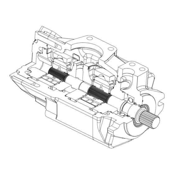
Section I — Introduction A. P urpose of Manual This manual has been prepared The general series of models to assist the users of Danfoss ’s covered are VMQ125S, high performance VMQ single VMQ135S, VMQ145S, pumps in properly installing, VMQ125T, VMQ135T,... - Page 4 Section II — Description (cont.) Cover/Housing O-Ring Outlet Cover Inlet Housing Housing/Body O-Ring Figure 1b. Cutaway View of Typical High Performance VMQ Double Vane Pump Outlet Section Cutaway View of Typical High Performance VMQ Triple Vane Pump Figure 1c. Single, Double, T riple and Thru-drive Pumps Overhaul Service Manual V-PUVN-TS001-E October 2002...
-
Page 5: Model Code
Model Code — Single and Thru- Drive Pumps VMQ1 1 2 3 4 7 8 9 10 11 12 13 14 15 16 17 18 19 20 21 22 23 24 25 26 27 28 – (Frame sizes 35 & 45 only) 1 2 3 4 13 14 Series designation... - Page 6 Model Code — Double Pumps VMQ2 1 2 3 4 9 10 11 1213 14 15 16 17 18 19 20 21 22 25 26 27 28 29 30 31 32 33 34 35 02 – SAE J744 splined 032 – 32 cm /r (1.96 in 1 2 3 4...
- Page 7 Model Code — Triple Pumps VMQ3 00 * 0 30 1 2 3 4 9 10 11 12 13 14 15 1617 18 19 20 21 22 30 31 33 34 35 Frame size 35 05 – SAE J744 keyed 1 2 3 4 Series designation Rear outlet port position...
-
Page 8: Assembly And Construction
Section II — Description (cont.) B. Assembly and Construction Basic Pumps. The pump outlet support plate, two wafer illustrated in Figure 1 is plates on either side of the representative of all single cam ring, and twelve vanes pumps in this series. The pump and under vane pins tted to consists principally of an inlet the rotor slots. -
Page 9: Hydraulic Balance
Section III — Principles of Operation (cont.) Inlet Window Vane Cross Section Pressure Balance Holes in Vane Under Vane Pin Rotor Terminal Hole Rotor Bushing Wafer Plate Outlet Window Rotor Figure 4. VMQ Wafer Plate, Rotor and Vanes C. Hy draulic Balance The pump ring is shaped so hydraulic forces which the two pumping chambers are... -
Page 10: Outlet Bodies
20 PSIG (1.38 bar). Higher Double shaft seal models pressure shaft seals are utilize a drain hole opening available. See your Danfoss sales between the two seals. This representative for further drain hole is used to prevent details. -
Page 11: Shaft Rotation
Clean uid is the best design will insure that aeration insurance for long service life. of the oil is kept to a minimum. Danfoss recommends a uid Single, Double, T riple and Thru-drive Pumps Overhaul Service Manual V-PUVN-TS001-E October 2002... -
Page 12: Overload Protection
Section IV — Installation and Operating Instructions (cont.) E. Hy draulic Fluid Recommendations (cont.) Sound Lev el purged of such air in the time it remains in the reservoir and air Noise is indirectly af fected by will be recycled through the the uid selection, but the system. -
Page 13: Inspection And Maintenance
Section V — Inspection and Maintenance A. Inspection Periodic inspection of the uid 2. Clean uid is the best 4. Air bubbles in the reser voir condition and tube or piping insurance for long service life. can ruin the pump and other connections reduce time Therefore, the reservoir should components. - Page 14 Section V — Inspection and Maintenance (cont.) Troubleshooting Chart Table 4. TROUBLE Pump not delivering uid. Driven in the wrong direction of rotation. The drive direction must be changed immediately to prevent seizure. Refer to Section VI.C. for the correct ring position for each direction of rotation.
- Page 15 Section V — Inspection and Maintenance (cont.) Figure 9a. Exploded V iew of VMQ Single Pump Outlet Body Cover/Body O-Ring Bearing Secondary Seal O-Ring Retaining Ring Back Up Ring O-Ring Primary Seal Shafts Retaining Ring Outlet Support Plate Back Up Ring Anti Rotation Torque Pin Inlet Cover Assembly Pin...
- Page 16 Section V — Inspection and Maintenance (cont.) Exploded V iew of VMQ Thru-Drive Pump Figure 8b. O-Rings Inlet Housing Thru-Drive Coupling Thru-Drive Adapter Thru-Drive Shafts Table 6 - Thru-Drive Pump Housing Torque Specs INLET HOUSING THRU-DRIVE ADAPTOR (SAE A & SAE B) THRU-DRIVE ADAPTOR (SAE C) ISO (NM) SAE (ft...
- Page 17 Section V — Inspection and Maintenance (cont.) Exploded V iew of VMQ Double Pump Figure 9c. Inlet Housing Outlet Cover Table 7 - Double and Triple Pump Housing Torque Specs INLET HOUSING ISO (NM) SAE (ft ISO (NM) SAE (ft ISO (NM) SAE (ft •...
- Page 18 Section V — Inspection and Maintenance (cont.) Exploded V iew of VMQ Triple Pump Figure 9d. Outlet Section Table 7 - Double and Triple Pump Housing Torque Specs INLET HOUSING ISO (NM) SAE (ft ISO (NM) SAE (ft ISO (NM) SAE (ft •...
-
Page 19: Overhaul
C. Driv e Reversal The rotation of Danfoss cartridge kits can easily be changed from clockwise to counterclockwise, or vice versa, by following the steps outlined below:... -
Page 20: Inspection And Repair
Section VI — Overhaul (cont.) C. Driv e Reversal (cont.) TABLE 8. CARTRIDGE KIT BUSHING LOCATIONS AND KIT ROTATION SETUP (location of bushing in cartridge kit, assuming a right hand rotation shaft) R = right hand rotation kit L = left hand rotation kit Pump Shaft End Kit Center Kit... -
Page 21: Assembly
Section VI — Overhaul (cont.) E. Assembly Basic pump: Clamp the body snap ring groove behind the in a vise or place on 2 x 4 bearing. wood blocks to facilitate 6. Inst all the O-rings and back- assembly. See gures 10 up ring on the cartridge outlet and 11. - Page 23 Phone: +45 7488 2222 Phone: +86 21 2080 6201 Danfoss can accept no responsibility for possible errors in catalogues, brochures and other printed material. Danfoss reserves the right to alter its products without notice. This also applies to products agreed.
Need help?
Do you have a question about the Vickers VMQ125S and is the answer not in the manual?
Questions and answers