
Related Manuals for Dell Alienware Aurora R15


Summary of Contents for Dell Alienware Aurora R15
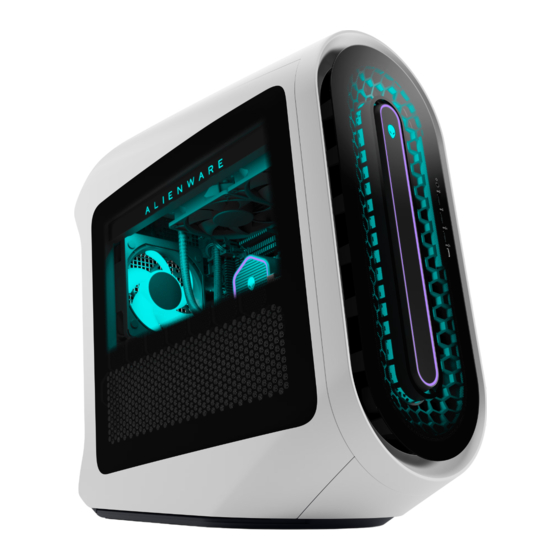
- Page 1 Alienware Aurora R15 Service Manual Regulatory Model: D30M Regulatory Type: D30M004 July 2023 Rev. A02...
- Page 2 A WARNING indicates a potential for property damage, personal injury, or death. © 2022-2023 Dell Inc. or its subsidiaries. All rights reserved. Dell Technologies, Dell, and other trademarks are trademarks of Dell Inc. or its subsidiaries. Other trademarks may be trademarks of their respective owners.
-
Page 3: Table Of Contents
Contents Chapter 1: Working inside your computer..................6 Before working inside your computer..........................6 Safety instructions................................6 Safety precautions................................7 Electrostatic discharge—ESD protection........................7 ESD field service kit ................................8 Transporting sensitive components..........................9 After working inside your computer..........................9 Chapter 2: Removing and installing components................10 Inside view of your computer............................10 System-board components............................. - Page 4 Removing the power-supply unit..........................35 Installing the power-supply unit..........................37 Removing the power-supply unit (1350 W)......................39 Installing the power-supply unit (1350 W)......................41 Coin-cell battery................................44 Removing the coin-cell battery..........................44 Installing the coin-cell battery..........................45 Memory modules................................46 Removing the memory modules..........................46 Installing the memory modules..........................
- Page 5 Top-chassis fan..................................83 Removing the top-chassis fan..........................83 Installing the top-chassis fan............................83 VR heat sink..................................84 Removing the VR heat sink............................84 Installing the VR heat sink............................86 System board..................................87 Removing the system board............................. 87 Installing the system board............................92 Chapter 3: Drivers and downloads....................97 Chapter 4: System setup......................
-
Page 6: Chapter 1: Working Inside Your Computer
You should only perform troubleshooting and repairs as authorized or directed by the Dell technical assistance team. Damage due to servicing that is not authorized by Dell is not covered by your warranty. See the safety instructions that is shipped with the product or at www.dell.com/regulatory_compliance. -
Page 7: Safety Precautions
ESD protection is an increasing concern. Due to the increased density of semiconductors used in recent Dell products, the sensitivity to static damage is now higher than in previous Dell products. For this reason, some previously approved methods of handling parts are no longer applicable. -
Page 8: Esd Field Service Kit
Always place parts in your hand, on the ESD mat, in the system, or inside an anti-static bag. ● Transporting Sensitive Components – When transporting ESD sensitive components such as replacement parts or parts to be returned to Dell, it is critical to place these parts in anti-static bags for safe transport. Working inside your computer... -
Page 9: Transporting Sensitive Components
Transporting sensitive components When transporting ESD sensitive components such as replacement parts or parts to be returned to Dell, it is critical to place these parts in anti-static bags for safe transport. -
Page 10: Chapter 2: Removing And Installing Components
Removing and installing components NOTE: The images in this document may differ from your computer depending on the configuration you ordered. Inside view of your computer 1. Side light (optional) 2. Liquid-cooling fan assembly (optional) 3. Upper front-chassis fan 4. Memory modules 5. - Page 11 9. SMA cable 10. Lower front-chassis fan 11. 3.5-inch hard drive 12. Graphics card 13. Graphics-card bracket (optional) 14. Power-supply unit bracket 15. Power-supply unit 16. Liquid-cooling assembly (optional) 17. Rear-chassis fan (optional) NOTE: The optional components may not be present in your computer, depending on its configuration. 1.
-
Page 12: System-Board Components
System-board components Figure 1. System-board components 1. Front I/O-panel cable 2. SYSFAN_LED3 connector 3. Upper front-chassis connector (FAN_SYS3) 4. Coin-cell battery 5. Wireless-card slot 6. SYSFAN_LED2 connector 7. Lower front-chassis fan connector (FAN_SYS2) 8. SATA 6 Gbps drive connector (HDD1) 9. -
Page 13: Recommended Tools
15. PCI-Express x4 slot (SLOT2) 16. PCI-Express x16 mechanical/x16 electrical slot (SLOT1) 17. Rear-chassis fan connector (FAN SYS1) 18. Rear-chassis fan LED connector (LED FAN SYS1) 19. Liquid cooling pump fan connector (FAN PUMP) 20. Liquid-cooling pump LED connector 21. Power-supply connector (ATX3) 22. -
Page 14: Antenna
Table 1. Screw list (continued) Component Screw type Quantity Screw image Solid-state drive (M.2 slot one) M2x3 Solid-state drive (M.2 slot two) M2x3 Wireless card M2x3 System board #6-32x1/4" Front I/O bracket #6-32x1/4" Liquid-cooling assembly fan #6-32x1/4" Antenna Removing the antenna Prerequisites 1. -
Page 15: Installing The Antenna
Steps 1. Loosen the bolts that connect the antenna cables to the SMA connectors on the chassis. 2. Remove the antenna cables off the SMA connectors on the chassis to disconnect the external antenna from the computer. Next steps 1. Follow the procedure in After working inside your computer. -
Page 16: Installing The Cable Cover
About this task The following image indicates the location of the cable cover and provides a visual representation of the removal procedure. NOTE: The cable cover is an optional accessory. Steps Pull the cable cover from the top to lift the cable cover from the chassis. Installing the cable cover Prerequisites If you are replacing a component, remove the existing component before performing the installation procedure. -
Page 17: Left-Side Cover
Steps 1. Align the cable cover with the slots at the rear of the chassis. 2. Slide the cable cover back into its place on the rear of the chassis. Next steps 1. Follow the procedure in After working inside your computer. -
Page 18: Installing The Left-Side Cover
Steps 1. Loosen the captive screw (#6-32) that secures the side-cover release latch to the chassis. 2. Pull the side-cover release latch to release the left-side cover away from the chassis. 3. Lift the left-side panel from the chassis. Installing the left-side cover Prerequisites If you are replacing a component, remove the existing component before performing the installation procedure. -
Page 19: Top Cover
Steps 1. Locate the tabs on the left-side cover and slots on the chassis. 2. Rotate the left-side cover towards the chassis until it snaps into place. 3. Tighten the captive screw (#6-32) that secures the side-cover release latch to the chassis. Next steps 1. - Page 20 Steps 1. Press your thumbs down at the rear of the top cover, and use your fingers to pull the two rear latches out to loosen the top cover at its rear. NOTE: The top cover is secured tight to the chassis by four latches. 2.
-
Page 21: Installing The Top Cover
Installing the top cover Prerequisites If you are replacing a component, remove the existing component before performing the installation procedure. About this task The following images indicate the location of the top cover and provides a visual representation of the installation procedure. Steps Align the tabs on the top cover with the slots on the chassis and snap the top cover into place. -
Page 22: Installing The Right-Side Cover
Steps 1. Knock the top rear tab of the right-side cover until the top of right-side cover is detached from the chassis. 2. Knock the bottom rear tab of the right-side cover until the bottom of the right-side cover is detached from the chassis. 3. -
Page 23: Front Bezel
About this task Steps 1. Align the tabs on the right-side cover with the slots on the chassis. 2. Push the right-side cover towards the chassis until it snaps into place. Next steps 1. Install the cover. 2. Install the left-side cover. -
Page 24: Installing The Front Bezel
Steps 1. Place the computer in an upright position. 2. Disconnect the front I/O-panel cable from the system board. 3. Pull the tabs of the front bezel from the slots on the front panel. NOTE: Start with tab on top, proceed to the tabs on the left of the front bezel, and then to the tabs on the right of the front bezel. - Page 25 About this task The following images indicate the location of the front bezel and provide a visual representation of the installation procedure. Steps 1. Align the front bezel with the front panel. 2. Route the front I/O-panel cable through the slot on the front panel. 3.
-
Page 26: Side Light
2. Install the cover. 3. Install the left-side cover. 4. Follow the procedure in After working inside your computer. Side light Removing the side light Prerequisites 1. Follow the procedure in Before working inside your computer. 2. Remove the left-side cover. -
Page 27: Installing The Side Light
3. Remove the side-light cable from the securing clip on the chassis. 4. Remove the two screws (M3x5) that secure the side light to the chassis. 5. Lift the left side of the side-light bar slightly from the screw hole at the rear of the chassis. 6. -
Page 28: 2.5-Inch Hard Drive
Next steps 1. Install the front bezel. 2. Install the right-side cover. 3. Install the cover. 4. Install the left-side cover. 5. Follow the procedure in After working inside your computer. 2.5-inch hard drive Removing the 2.5-inch hard drive Prerequisites 1. -
Page 29: Installing The 2.5-Inch Hard Drive
Steps 1. Disconnect the data and power cables from the hard drive. 2. Press the release tabs on the hard-drive carrier and slide the hard-drive carrier out of the hard-drive cage. 3. Pry the hard-drive carrier to release the tabs on the carrier from the slots on the hard drive. 4. - Page 30 NOTE: Note the orientation on the hard-drive carrier to replace it correctly. Steps 1. Align the hard drive with the pins on the hard-drive carrier. 2. Using the tabs on the opposite side, flex open the carrier to insert the pins on the other side. 3.
-
Page 31: 3.5-Inch Hard Drive
(BIOS). NOTE: To install the operating system on to your storage device, see Reinstall Windows to the Dell factory image using recovery media in the Knowledge Base Resource at www.dell.com/support. 3.5-inch hard drive Removing the 3.5-inch hard drive Prerequisites 1. - Page 32 Steps 1. Disconnect the data and power cables from the hard drive. 2. Press the release tabs on the hard-drive carrier and slide the hard-drive carrier out of the hard-drive cage. 3. Pry the hard-drive carrier to release the tabs on the carrier from the slots on the hard drive. 4.
-
Page 33: Installing The 3.5-Inch Hard Drive
NOTE: Note the orientation of the hard drive so that you can replace it correctly. Installing the 3.5-inch hard drive Prerequisites If you are replacing a component, remove the existing component before performing the installation procedure. About this task The following images indicate the location of the 3.5-inch hard drive and provide a visual representation of the installation procedure. - Page 34 Removing and installing components...
-
Page 35: Identifying The Storage Device In Device Manager
(BIOS). NOTE: To install the operating system on to your storage device, see Reinstall Windows to the Dell factory image using recovery media in the Knowledge Base Resource at www.dell.com/support. Identifying the storage device in Device Manager Steps 1. - Page 36 About this task The following images indicate the location of the power-supply unit and provide a visual representation of the removal procedure. Removing and installing components...
-
Page 37: Installing The Power-Supply Unit
Steps 1. Disconnect the power-supply unit cables from the power-supply unit extension cables on the right side of the computer. 2. Note the cable routing when removing the power-supply unit cables through the slot on the right side of the computer. 3. - Page 38 Steps 1. Lay the computer on the right side. 2. Slide and place the power-supply unit on the chassis. 3. Align the screw holes on the power-supply unit with the screw holes on the chassis. 4. Replace the four screws (#6-32x1/4") that secure the power-supply unit to the chassis. 5.
-
Page 39: Removing The Power-Supply Unit (1350 W)
6. Replace the two screws (#6-32x1/4") that secure the power-supply unit bracket to the power-supply unit. 7. Replace the graphics-card bracket and slide the release latch to the lock position. 8. Route the power-supply unit cables through the securing clip. 9. - Page 40 2. Note the cable routing when removing the power-supply unit cables through the slot on the right side of the computer. Removing and installing components...
-
Page 41: Installing The Power-Supply Unit (1350 W)
3. Lay the computer on the right side. 4. Release the power-supply unit cables from the securing clip. 5. Press the release clips on the power-supply connectors and disconnect the power-supply cables from the system board. 6. Press the release clips on the graphics-card power connectors and disconnect the graphics-card power cables from the power-supply unit. - Page 42 WARNING: The cable management varies depending on the configuration of the graphics card selected. For computers shipped with NVIDIA GeForce RTX 4090 and NVIDIA GeForce RTX 4080 graphics card, do not route the graphics card power cable into the clip of graphics card end holder. About this task The following images indicate the location of the power-supply unit and provide a visual representation of the installation procedure.
- Page 43 9. Connect the power-supply cables to the system board. 10. Connect the graphics-card power cables to the power-supply unit. 11. Place the computer in an upright position. 12. Route the power-supply unit cables through the slot on the right side of the computer. 13.
-
Page 44: Coin-Cell Battery
Next steps 1. Install the lower front-chassis fan. 2. Install the rear-chassis fan. 3. Install the single-graphics card. 4. Install the right-side cover. 5. Install the left-side cover. 6. Follow the procedure in After working inside your computer. Coin-cell battery Removing the coin-cell battery Prerequisites 1. -
Page 45: Installing The Coin-Cell Battery
WARNING: Before working inside your computer, read the safety information that is shipped with your computer. For more safety best practices, see the Regulatory Compliance home page at www.dell.com/ regulatory_compliance. CAUTION: Removing the coin-cell battery resets the BIOS setup program’s settings to default. It is recommended that you note the BIOS setup program’s settings before removing the coin-cell battery. -
Page 46: Memory Modules
Steps Insert the new coin-cell battery (CR2032) into the battery socket with the positive side facing up, and snap the battery into place. Next steps 1. Install the left-side cover. 2. Follow the procedure in After working inside your computer. Memory modules Removing the memory modules Prerequisites... -
Page 47: Installing The Memory Modules
Steps 1. Lay the computer on the right side. 2. Push the securing clips away from the memory module. 3. Lift the memory module off the memory-module slot. NOTE: Repeat step 2 to step 3 to remove any other memory modules installed in your computer. CAUTION: To prevent damage to the memory module, hold the memory module by the edges. - Page 48 Steps 1. Ensure that the securing clips are extended away from the memory-module slot. 2. Align the notch on the memory module with the tab on the memory-module slot. 3. Insert the memory module into the memory-module slot and press the memory module down until it snaps into position and the securing clips lock in place.
-
Page 49: Single-Graphics Card
Single-graphics card Removing the single-graphics card Prerequisites 1. Follow the procedure in Before working inside your computer. 2. Remove the left-side cover. About this task The following images indicate the location of the single-graphics card and provide a visual representation of the removal procedure. -
Page 50: Installing The Single-Graphics Card
Steps 1. Lay the computer on the right side. 2. Slide the release latch to its unlock position and lift the graphics-card end holder away from the PCIe fan. NOTE: Skip this step if your graphics card does not ship with a graphics-card end holder. 3. - Page 51 Steps 1. Place the card into the PCIe slot and press down firmly until the single-graphics card snaps into place. 2. Close the expansion-card door and snap the latch back into position. 3. Replace the graphics-card end holder over the PCIe fan and slide the latch into its lock position. NOTE: Skip this step if your graphics card does not ship with a graphics-card end holder.
-
Page 52: Graphics-Card Bracket And Graphics-Card End Holder
After working inside your computer. Graphics-card bracket and graphics-card end holder The following table shows whether the graphics-card bracket or/and the graphics-card end holder is/are shipped with your Alienware Aurora R15. Table 3. Graphics-card bracket and graphics-card end holder Graphics card Graphics-card bracket... -
Page 53: Installing The 2230 Solid-State Drive In Ssd Slot One
Steps 1. Remove the screw (M2x3) that secures the 2230 solid-state drive to the system board. 2. Slide and lift the 2230 solid-state drive off solid-state drive slot one on the system board. Installing the 2230 solid-state drive in SSD slot one Prerequisites If you are replacing a component, remove the existing component before performing the installation procedure. -
Page 54: Removing The 2280 Solid-State Drive In Ssd Slot One
(BIOS). NOTE: To install the operating system on to your storage device, see Reinstall Windows to the Dell factory image using recovery media in the Knowledge Base Resource at www.dell.com/support. Removing the 2280 solid-state drive in SSD slot one Prerequisites 1. -
Page 55: Installing The 2280 Solid-State Drive In Ssd Slot One
Steps 1. Remove the screw (M2x3) that secures the 2280 solid-state drive to the system board. 2. Slide and lift the 2280 solid-state drive off SSD slot one on the system board. Installing the 2280 solid-state drive in SSD slot one Prerequisites If you are replacing a component, remove the existing component before performing the installation procedure. -
Page 56: Removing The 2230 Solid-State Drive In Ssd Slot Two
(BIOS). NOTE: To install the operating system on to your storage device, see Reinstall Windows to the Dell factory image using recovery media in the Knowledge Base Resource at www.dell.com/support. Removing the 2230 solid-state drive in SSD slot two Prerequisites 1. -
Page 57: Installing The 2230 Solid-State Drive In Ssd Slot Two
Steps 1. Remove the screw (M2x3) that secures the 2230 solid-state drive to the system board. 2. Slide and lift the 2230 solid-state drive off SSD slot two on the system board. Installing the 2230 solid-state drive in SSD slot two Prerequisites If you are replacing a component, remove the existing component before performing the installation procedure. -
Page 58: Removing The 2280 Solid-State Drive In Ssd Slot Two
(BIOS). NOTE: To install the operating system on to your storage device, see Reinstall Windows to the Dell factory image using recovery media in the Knowledge Base Resource at www.dell.com/support. Removing the 2280 solid-state drive in SSD slot two Prerequisites 1. -
Page 59: Installing The 2280 Solid-State Drive In Ssd Slot Two
Steps 1. Remove the screw (M2x3) that secures the 2280 solid-state drive to the system board. 2. Slide and lift the 2280 solid-state drive off SSD slot two on the system board. Installing the 2280 solid-state drive in SSD slot two Prerequisites If you are replacing a component, remove the existing component before performing the installation procedure. -
Page 60: Processor Fan And Heat-Sink Assembly
(BIOS). NOTE: To install the operating system on to your storage device, see Reinstall Windows to the Dell factory image using recovery media in the Knowledge Base Resource at www.dell.com/support. Processor fan and heat-sink assembly... -
Page 61: Installing The Processor Fan And Heat-Sink Assembly
About this task The following images indicate the location of the processor fan and heat-sink assembly and provide a visual representation of the removal procedure. Steps 1. Lay the computer on the right side. 2. Disconnect the processor-fan cable from the system board. 3. -
Page 62: Processor Liquid-Cooling Assembly
Steps 1. Place the processor fan and heat-sink assembly on the processor. 2. Align the captive screws on the processor fan heat-sink assembly with the screw holes on the system board. 3. In sequential order, tighten the four captive screws that secure the processor fan and heat-sink assembly to the system board. - Page 63 About this task The following images indicate the location of the processor liquid-cooling assembly and provide a visual representation of the removal procedure. Steps 1. Lay the computer on the right side. 2. Lift the side light bar. 3. Remove the two screws (M3x5) that secures the radiator and fan assembly to the chassis. 4.
-
Page 64: Installing The Processor Liquid-Cooling Assembly
7. Release the spring latch and lift the processor-cooling assembly, along with the cables, off the system board. Installing the processor liquid-cooling assembly Prerequisites If you are replacing a component, remove the existing component before performing the installation procedure. CAUTION: Incorrect alignment of the processor liquid-cooling assembly can damage the system board and processor. - Page 65 Steps 1. Align the screw hole of the radiator and fan assembly to the screw hole on the chassis and make sure that the spring latch is locked. NOTE: Ensure that the hoses are facing the front of the computer. 2.
-
Page 66: Liquid-Cooling Assembly Fan
7. Push the side light bar down. Next steps 1. Install the left-side cover. 2. Follow the procedure in After working inside your computer. Liquid-cooling assembly fan Removing the liquid-cooling assembly fan Prerequisites 1. Follow the procedure in Before working inside your computer. -
Page 67: Installing The Liquid-Cooling Assembly Fan
Steps 1. Remove the four screws (#6-32x1/4") that secures the left liquid-cooling assembly fan to the liquid-cooling assembly. 2. Lift the left liquid-cooling assembly fan off the liquid-cooling assembly. 3. Remove the four screws (#6-32x1/4") that secures the right liquid-cooling assembly fan to the liquid-cooling assembly. 4. -
Page 68: Processor
Steps 1. Align and place the left liquid-cooling assembly fan on the liquid-cooling assembly. 2. Replace the four screws (#6-32x1/4") that secures the left liquid-cooling assembly fan to the liquid-cooling assembly. 3. Align and place the right liquid-cooling assembly fan off the liquid-cooling assembly. 4. -
Page 69: Installing The Processor
About this task The following images indicate the location of the processor and provide a visual representation of the removal procedure. Steps 1. Press the release lever down and then push it away from the processor to release it from the tab. 2. - Page 70 Steps 1. Ensure that the release lever on the processor socket is fully extended and the processor cover is fully open. CAUTION: Position the processor correctly in the processor socket to avoid permanent damage to the processor. 2. Align the pin-1 corner on the processor with the pin-1 corner on the processor socket, and then place the processor in the processor socket.
-
Page 71: Wireless Card
Wireless card Removing the wireless card Prerequisites 1. Follow the procedure in Before working inside your computer. 2. Remove the left-side cover. About this task The following images indicate the location of the wireless card and provide a visual representation of the removal procedure. Steps 1. - Page 72 About this task The following images indicate the location of the wireless card and provide a visual representation of the installation procedure. Steps 1. Connect the antenna cables to the wireless card. The following table provides the antenna-cable color scheme for the wireless card supported by your computer. Table 4.
-
Page 73: Sma Cable
SMA cable Removing the SMA cable Prerequisites 1. Follow the procedure in Before working inside your computer. 2. Remove the left-side cover. 3. Remove the single-graphics card. 4. Remove the wireless card. About this task The following images indicate the location of an SMA cable and provide a visual representation of the removal procedure. Removing and installing components... -
Page 74: Installing The Sma Cable
Steps 1. Remove the washer and nuts that secure the SMA cable connector to the chassis. 2. Route the SMA cable assembly through the slot on the rear I/O. 3. Remove the SMA cable from the securing clip on the system board. 4. - Page 75 Removing and installing components...
-
Page 76: Rear-Chassis Fan
Steps 1. Align and place the SMA cable connector on the chassis. 2. Route the SMA cable under the PCIe x16 slot. 3. Insert the SMA cable to the securing clip on the system board. 4. Route the SMA cable assembly through the slot on the rear I/O. 5. -
Page 77: Installing The Rear-Chassis Fan
Steps 1. Lay the computer on its right side. 2. Disconnect the rear-chassis fan cable from the system board. 3. Remove the screw (M3x5) that secures the rear-chassis fan to the chassis. 4. Slide and lift the rear-chassis off the chassis. Installing the rear-chassis fan Prerequisites If you are replacing a component, remove the existing component before performing the installation procedure. -
Page 78: Lower Front-Chassis Fan
Steps 1. Lay the computer on its right side. 2. Align the rear-chassis fan with the slot on the chassis. 3. Replace the screw (M3x5) that secures the rear-chassis fan to the chassis. 4. Connect the rear-chassis fan cable to the system board. Next steps 1. -
Page 79: Installing The Lower Front-Chassis Fan
2. Remove the left-side cover. About this task The following images indicate the location of the lower front-chassis fan and provide a visual representation of the removal procedure. Steps 1. Lay the computer on its right side. 2. Disconnect the lower front-chassis fan cable from the system board. 3. - Page 80 About this task The following images indicate the location of the lower front-chassis fan and provide a visual representation of the installation procedure. Steps 1. Lay the computer on its right side. 2. Align the tabs on the lower front-chassis fan with the slots on the chassis. 3.
-
Page 81: Upper Front-Chassis Fan
Upper front-chassis fan Removing the upper front-chassis fan Prerequisites 1. Follow the procedure in Before working inside your computer. 2. Remove the left-side cover. About this task The following images indicate the location of the upper front-chassis fan and provide a visual representation of the removal procedure. -
Page 82: Installing The Upper Front-Chassis Fan
Installing the upper front-chassis fan Prerequisites If you are replacing a component, remove the existing component before performing the installation procedure. About this task The following images indicate the location of the upper front-chassis fan and provide a visual representation of the installation procedure. -
Page 83: Top-Chassis Fan
Top-chassis fan Removing the top-chassis fan Prerequisites 1. Follow the procedure in Before working inside your computer. 2. Remove the left-side cover. About this task The following images indicate the location of the top-chassis fan and provide a visual representation of the removal procedure. Steps 1. -
Page 84: Vr Heat Sink
About this task The following images indicate the location of the top-chassis fan and provide a visual representation of the installation procedure. Steps 1. Lay the computer on the right side. 2. Align and place the top-chassis fan on the chassis. 3. - Page 85 About this task The following images indicate the location of the VR heat sink and provide a visual representation of the removal procedure. Removing and installing components...
-
Page 86: Installing The Vr Heat Sink
Steps 1. Lay the computer on the right side. 2. Loosen the captive screws that secure the VR heat sink to the system board. 3. Repeat the same process for the other VR heat sink. 4. Lift the VR heat sink (2) off the system board. Installing the VR heat sink Prerequisites If you are replacing a component, remove the existing component before performing the installation procedure. -
Page 87: System Board
Steps 1. Align the captive screws of the VR heat sink with the screw holes on the system board. 2. Tighten the two captive screws that secure the VR heat sink to the system board. 3. Repeat the same procedure for the other VR heat sink. Next steps 1. - Page 88 2. Remove the left-side cover. 3. Remove the cover. 4. Remove the right-side cover. 5. Remove the front bezel. 6. Remove the memory modules. 7. Remove the single-graphics card. 8. Remove the 2230 solid-state drive or the 2280 solid-state drive in SSD slot one, as applicable.
- Page 89 Figure 2. System-board connectors 1. Front I/O-panel cable 2. SYSFAN_LED3 connector 3. Upper front-chassis connector (FAN_SYS3) 4. Coin-cell battery 5. Wireless-card slot 6. SYSFAN_LED2 connector 7. Lower front-chassis fan connector (FAN_SYS2) 8. SATA 6 Gbps drive connector (HDD1) 9. SATA 6 Gbps drive connector (HDD2) 10.
- Page 90 19. Liquid cooling pump fan connector (FAN PUMP) 20. Liquid-cooling pump LED connector 21. Power-supply connector (ATX3) 22. Top-chassis fan connector one (FAN_SYS4) 23. Power-supply connector (ATX2) 24. CPU socket 25. Top-chassis fan connector two (FAN_SYS5) 26. Memory-module slot, DIMM1 27.
- Page 91 Steps 1. Disconnect the hard-drive data cables from the system board. 2. Disconnect the processor-power cables from the system board. 3. Disconnect the system-board power cables from the system board. 4. Disconnect the top-chassis fan power cable from the system board. 5.
-
Page 92: Installing The System Board
Installing the system board Prerequisites If you are replacing a component, remove the existing component before performing the installation procedure. About this task The following image indicates the connectors on your system board. Figure 3. System-board components 1. Front I/O-panel cable 2. - Page 93 3. Upper front-chassis connector (FAN_SYS3) 4. Coin-cell battery 5. Wireless-card slot 6. SYSFAN_LED2 connector 7. Lower front-chassis fan connector (FAN_SYS2) 8. SATA 6 Gbps drive connector (HDD1) 9. SATA 6 Gbps drive connector (HDD2) 10. Power-supply connector (ATX1) 11. Solid-state drive slot (M.2 PCIe SSD-1) 12.
- Page 94 Removing and installing components...
- Page 95 Steps 1. Slide the front I/O-ports on the system board into the front I/O-slot on the chassis and align the screw holes on the system board with the standoffs on the chassis. 2. Place the system board on the standoffs on the chassis. 3.
- Page 96 4. Install the wireless card. 5. Install the 2230 solid-state drive or the 2280 solid-state drive in SSD slot one, as applicable. 6. Install the 2230 solid-state drive or the 2280 solid-state drive in SSD slot two, as applicable. 7. Install the single-graphics card.
-
Page 97: Chapter 3: Drivers And Downloads
Drivers and downloads When troubleshooting, downloading or installing drivers it is recommended that you read the Dell Knowledge Base article, Drivers and Downloads FAQ 000123347. Drivers and downloads... -
Page 98: Chapter 4: System Setup
Boot Sequence allows you to bypass the System Setup–defined boot device order and boot directly to a specific device (for example: optical drive or hard drive). During the Power-on Self Test (POST), when the Dell logo appears, you can: ● Access System Setup by pressing F2 key... -
Page 99: System Setup Options
Displays the current date in mm/dd/yy format. BIOS Version Displays the BIOS version number. Product Name Displays the product name. Default: Alienware Aurora R15 Service Tag Displays the service tag of your computer. Asset Tag Displays the asset tag of your computer. - Page 100 Table 7. System setup options—Advanced menu (continued) Advanced HyperThread Control HyperThread Control Enables or disables HyperThread Control. Default: Enabled Multiple-Core Support Multiple-Core Support Allows you to configure Multiple-Core support. Default: All Multiple Atom cores Multiple Atom cores Allows you to configure Multiple Atom cores. Default: All Trusted Execution Trusted Execution...
- Page 101 Table 7. System setup options—Advanced menu (continued) Advanced USB Wake Support Allows you to enable the USB devices to wake the system from Standby. Default: Enabled USB PowerShare in S4/S5 state Allows you to charge external devices. Default: Disabled USB PowerShare in Sleep State Allows you to enable front the USB devices to wake the system from sleep state.
- Page 102 BIOS Auto-Recovery is not possible from other media. Default: Disabled SupportAssist System Resolution Controls the automatic boot flow for SupportAssist System Resolution Console and for Dell operating system Recovery tool. Default: 2 Auto OS Recovery Threshold Allows you to configure the Auto OS Recovery Threshold.
- Page 103 Table 8. System setup options—Security menu (continued) Security PPI Bypass for SED Block SID Command Allows you to enable or disable PPI Bypass for SED Block SID Command. Default: Disabled Password Change Allows you to enable or disable password change on the computer.
-
Page 104: System And Setup Password
Table 8. System setup options—Security menu (continued) Security ● Reset All Keys will reset all four keys to their default settings. Reset all Keys Delete all Keys Table 9. System setup options—Boot menu Boot Boot List Option Displays the available boot devices. Default: UEFI File Browser Add Boot Option Allows you to set the boot path in the boot option list. -
Page 105: Assigning A System Setup Password
NOTE: System and setup password feature is disabled. Assigning a system setup password Prerequisites You can assign a new System or Admin Password only when the status is in Not Set. About this task To enter the system setup, press F12 immediately after a power-on or reboot. Steps 1. -
Page 106: Clearing Cmos Settings
Clearing CMOS settings About this task CAUTION: Clearing CMOS settings will reset the BIOS settings on your computer. The following images indicate the location of the CMOS jumper on the system board and provide a visual representation of the clearing CMOS procedure. Steps 1. -
Page 107: Updating The Bios
Updating the BIOS Updating the BIOS in Windows Steps 1. Go to www.dell.com/support. 2. Click Product support. In the Search support box, enter the Service Tag of your computer, and then click Search. NOTE: If you do not have the Service Tag, use the SupportAssist feature to automatically identify your computer. You can also use the product ID or manually browse for your computer model. -
Page 108: Updating The Bios Using The Usb Drive In Windows
Time Boot menu on the computer. Most of the Dell computers built after 2012 have this capability, and you can confirm by booting your computer to the F12 One Time Boot Menu to see if BIOS FLASH UPDATE is listed as a boot option for your computer. If the option is listed, then the BIOS supports this BIOS update option. -
Page 109: Chapter 5: Troubleshooting
You should only perform troubleshooting and repairs as authorized or directed by the Dell technical support team. Damage due to servicing that is not authorized by Dell is not covered by your warranty. Table 12. Diagnostic light codes ... -
Page 110: Recovering The Operating System
It enables you to diagnose hardware issues, repair your computer, back up your files, or restore your computer to its factory state. You can also download it from the Dell Support website to troubleshoot and fix your computer when it fails to boot into their primary operating system due to software or hardware failures. -
Page 111: Drain Residual Flea Power (Perform Hard Reset)
3. Press and hold the power button for 20 seconds to drain the flea power. 4. Connect the power adapter to your computer. 5. Turn on your computer. NOTE: For more information about performing a hard reset, see the knowledge base article 000130881 www.dell.com/support. Troubleshooting... -
Page 112: Chapter 6: Getting Help And Contacting Alienware
Tag or Express Service Code. To view relevant support documents. resources for your Dell computer, enter the Service Tag or Express Service Code at www.dell.com/support. For more information on how to find the Service Tag for your...
Need help?
Do you have a question about the Alienware Aurora R15 and is the answer not in the manual?
Questions and answers