
Related Manuals for SunSynk SYNK-3.6K-SG04LP1


Summary of Contents for SunSynk SYNK-3.6K-SG04LP1
- Page 1 ECCO HYBRID INVERTER USER MANUAL SYNK-3.6K-SG04LP1 / SYNK-5K-SG04LP1 www.sunsynk.com sales@sunsynk.com customerservices@sunsynk.com PLEASE RETAIN FOR v.21 (12/11/23) FUTURE REFERENCE...
-
Page 2: Table Of Contents
Table of Contents SAFETY Setup Page Basic Setup General Safety Set Time (Clock) Symbols/Safety Signs Set Company Name / Beeper / Auto dim 35 Safety Instructions Factory Reset and Lock Code Product Disposal Inverter Remote Control Battery Setup Page PRODUCT INTRODUCTION Generator &... -
Page 3: Safety
SAFETY General Safety This device should only be used in accordance with the instructions within this manual and in compli- ƒ ance with local, regional, and national laws and regulations. Only allow this device to be installed, oper- ated, maintained, and repaired by other people who have read and understood this manual. Ensure the manual is included with this device should it be passed to a third party. - Page 4 15.70 A V DC 48 V V DC 48 V AC OUTPUT BATTERY INPUT 230V V DC 48 V Output Voltage, Input Voltage Type, Ac 230V Battery Discharge Voltage, Battery 15.70 A Output Rated Current, Max AC Current, 15.70 A Discharge Current, Input Voltage Type, Output Frequency, Max AC ISC, Power Battery Discharge Power.
-
Page 5: Safety Instructions
WARNING HIGH LIFE RISK DUE TO FIRE OR ELECTROCUTION. The Sunsynk Ecco Hybrid Inverter can only be installed by a qualified licensed electrical contractor. This is not a DIY product. This chapter contains important safety and operating instructions. Read and keep this manual for future ƒ... -
Page 6: Product Introduction
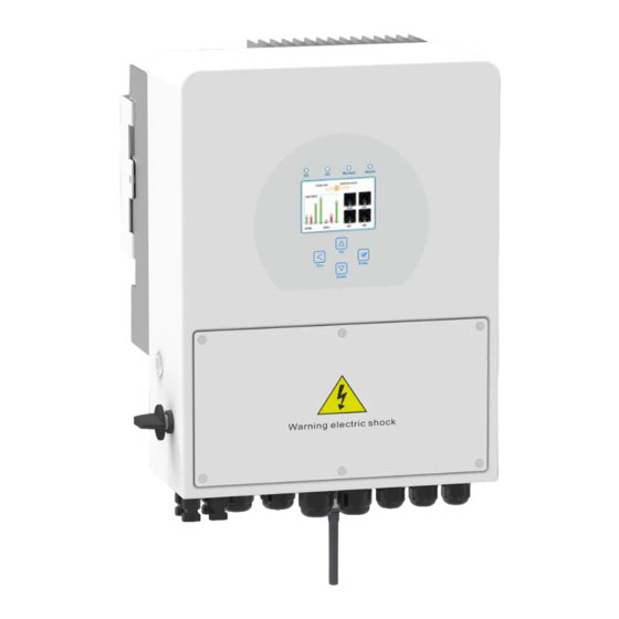
PRODUCT INTRODUCTION The Sunsynk Ecco Hybrid Inverter is a multifunctional inverter combines the functions of an inverter, solar charger and battery charger to offer uninterruptible power support with a portable size. Its comprehensive LCD display offers user-configurable and easily accessible button operations such as battery charging, AC/ solar charging, and acceptable input voltage based on different applications. -
Page 7: Product Size
Product Size Inverter Size ECCO SG04LP1 | User Manual... -
Page 8: Product Features
Product Features INTERACTIVE Easy and simple to understand display ƒ Supporting Wi-Fi or GSM monitoring ƒ Visual power flow screen ƒ Parallel / multi invert function grid-tied and off-grid ƒ COMPATIBLE Compatible with main electrical grid voltages or power generators ƒ Compatible with wind turbines ƒ... -
Page 9: Basic System Architecture
Basic System Architecture The following illustration shows the basic application of this inverter. It also includes following devices to have a complete running system. Generator or utility ƒ PV modules ƒ Consult with your system integrator for other possible system architectures depending on your require- ments. -
Page 10: Technical Specifications
TECHNICAL SPECIFICATIONS Model SYNK-3.6K-SG04LP1 SYNK-5K-SG04LP1 Battery Input Data Battery Type Lead-acid or Lithium-ion Battery Voltage Range 40~60V Max. Charging Current 120A Max. Discharging Current 120A Charging Curve 3 Stages/Equalisation Number of Battery Input Charging Strategy for Li-Ion Self-Adaptation to BMS... - Page 11 General Data Operating Temperature Range -45~60°C, >45°C Derating Cooling Natural Cooling Noise <30dB Communication with BMS RS485; CAN Weight 14.6kg 17.5kg Size 330W x 433H x 238D mm Protection Degree IP65 Installation Style Wall-mounted Warranty 5 years ECCO SG04LP1 | User Manual...
-
Page 12: Installation
INSTALLATION Parts List Check the equipment before installation. Please make sure nothing is damaged in the package. You should have received the items in the following package: Stainless Steel Anti-Collision Bolt M8x80 Wall Mounting Bracket Hybrid Inverter Stainless Steel Mounting Parallel Communication L-type Hexagon Wrench Screws M6x12 User Manual... -
Page 13: Selecting The Mounting Area
Selecting the Mounting Area This Sunsynk Ecco Hybrid Inverter is designed for outdoor use (IP65). DO NOT install the inverter in the following areas: Areas with high salt content, such as the marine environment. It will deteriorate the metal parts and pos- ƒ sibly lead to water/dampness penetrating the unit. Areas filled with mineral oil or containing splashed oil or steam such as found in kitchens. It will deterio- ƒ... -
Page 14: Mounting The Inverter
Install the indoor unit on the wall where the floor height is higher than 1600mm. ƒ For proper heat dissipation, allow a clearance of approximately 500mm to the side, 500mm above and ƒ below the unit, and 1000mm to the front of the unit. WARNING For proper air circulation to dissipate heat, allow a clearance of approx. -
Page 15: Battery Connection
Inverter Hanging Plate Installation Battery Connection For safe operation and compliance, a separate DC over-current protector or disconnect device is required between the battery and the inverter. In some applications, switching devices may not be required but over-current protectors are still required. Refer to the typical amperage in the table below for the required fuse or circuit breaker size. - Page 16 WARNING All wiring/connecting must be performed by qualified personnel. Ensure the inverter unit is wired correctly before making the final DC connection or closing the DC Breaker/disconnection device. A reverse-polarity connection on the battery will damage the inverter. Please follow below steps to implement battery connection: 1.
-
Page 17: Function Port Definition
Function Port Definition DIP Switch Inverter TEMP:1,2 CT:3,4 G-start:5,6 RS485/CAN Meter G-valve:7,8 1 2 3 4 5 6 7 8 parallel_1parallel_2 RS485/CAN: CAN port for battery communication. Meter: for energy meter communication. Parallel 1: Parallel communication port 1 Batt Temp (CAN interface). Gen start-up Sensor N/O Relay... -
Page 18: Connecting A Lithium Battery
Connecting a Lithium Battery When connecting a Lithium battery, follow the connection steps below and check ‘Setting up a Lithium Bat- tery’ to connect with an inverter. 1. Connect the correct diameter of cable in accordance with the battery manufacture specifications along with recommended safety devices. 2. -
Page 19: Lead-Acid Battery Temperature Sensor
Lead-Acid Battery Temperature Sensor Without a remote temperature sensor, lead-acid batteries may undercharge or overcharge depending on the ambient temperature of the installation environment. This may result in a fire hazard. Inverter Temp. sensor ECCO SG04LP1 | User Manual... -
Page 20: Connecting The Ac
Connecting the AC Before connecting to grid, please install a separate AC breaker between inverter and grid. Also, it is recom- mended that installs an AC breaker between backup load and inverter. This will ensure the inverter can be securely disconnected during maintenance and fully protected from over current. For the 3.6/5kW model, the recommended AC breaker for backup load is 40A. -
Page 21: Recommended Ac Surge Protector
LOAD GRID Recommended AC Surge Protector ECCO SG04LP1 | User Manual... -
Page 22: Pv Connection
1. Open-circuit voltage (Voc) does not exceed the max. PV array open-circuit voltage of the inverter. 2. Open-circuit voltage (Voc) should be higher than min. start voltage. 3. The PV modules connected to this inverter shall be Class A rating certified according to lEC 61730. Inverter Model SYNK-3.6K-SG04LP1 SYNK-5K-SG04LP1 PV Input Voltage 370V (125V~500V) -
Page 23: Pv Protection
Installing the CT Coil The CT coil is one of the most important parts of the Sunsynk Parity inverter. This device reduces the power of the inverter to prevent feeding power to the grid. This feature is also known as “Zero Export”. - Page 24 Inverter White wire Black wire Arrow pointing Grid to inverter The primary side of the CT needs to be clamped on the Grid live line. If the CT coil is fitted in the wrong way then this variable will have neg- ative instead of positive values when the power is flowing into the house/ inverter.
-
Page 25: Meter Connection
Meter Connection Connection for the CHNT Meter Inverter Breaker RS485/CAN Meter System connection diagram for the CHNT meter Grid Grid input Output RS 485 DDSU666 DIN-RAIL METER RS485A 230V 5(60) A 800imp/kWh RS485B CHNT DDSU666 CHINT meter ECCO SG04LP1 | User Manual... -
Page 26: Earth Connection (Mandatory)
Earth Connection (MANDATORY) An Earth Cable shall be connected to the earth plate on the grid size in order to prevent electric shock if the original protective conductor fails. All neutrals can be linked together to maintain the neutral bond. When a Neural Earth bond is required for an ‘Off-grid’... -
Page 27: Wiring System For Inverter
Wiring System for Inverter ECCO SG04LP1 | User Manual... -
Page 28: Single-Phase Parallel Connection
Inverter Inverter No.2 Breaker (slave) DC Breaker for battery SYNK-3.6K-SG04LP1: 120A DC breaker SYNK-5K-SG04LP1: 150A DC breaker Breaker AC Breaker for grid port SYNK-3.6K-SG04LP1: 40A AC breaker SYNK-5K-SG04LP1: 40A AC breaker AC Breaker for backup load port SYNK-3.6K-SG04LP1: 40A AC breaker... -
Page 29: Three-Phase Parallel Inverter
Three-Phase Parallel Inverter DC Breaker for battery SYNK-3.6K-SG04LP1: 120A DC breaker SYNK-5K-SG04LP1: 150A DC breaker AC Breaker for grid port SYNK-3.6K-SG04LP1: 40A AC breaker SYNK-5K-SG04LP1: 40A AC breaker AC Breaker for backup load SYNK-3.6K-SG04LP1: 40A AC breaker SYNK-5K-SG04LP1: 40A AC breaker AC Breaker... -
Page 30: Operation
OPERATION Switching ON/OFF Once the inverter has been correctly installed and the batteries have been connected, press the ON/OFF button (located on the left side of the case) to activate the system. When the system is connected without a battery but connected with either PV or grid and the ON/OFF button is switched off, the LCD will still illumi- nate (display will show off). -
Page 31: Lcd Operation Flow Chart
LCD Operation Flow Chart Solar Page Solar Graph Grid Page Grid Graph Inverter Page Battery Page BMS Page HOME PAGE Load Page Load Graph Basic Setting Battery Settings Grid Settings System Mode System Setup Advanced Settings Aux Load Settings Fault Codes Li BMS Settings ECCO SG04LP1 | User Manual... -
Page 32: Home Page
Home Page Press the Esc button any page to access the home page: 1. Customer name 2. Access the settings menu page 3. Access solar page 4. Access load page 5. Access battery page SOLAR/TURBINE AC load 6. Access grid page 7. -
Page 33: System Flow Page
What this page displays: Total solar power produced. Inverter voltage. ƒ ƒ MPPT 1 power/voltage/current. Inverter current. ƒ ƒ MPPT 2 power/voltage/current. Load power. ƒ ƒ Grid power. Load voltage. ƒ ƒ Grid frequency. Battery power charge/discharge. ƒ ƒ Grid voltage. Battery SOC. -
Page 34: Setup Page
What this page displays: The system flow. Battery status. ƒ ƒ MPPTs power. Power distribution to load or grid. ƒ ƒ Setup Page To access Settings, click on the gear icon on the right top of the navigation menu. What this page displays: Serial number. -
Page 35: Basic Setup
Basic Setup Set Time (Clock) To set time, click on the BASIC icon and then on ‘Time’ What this page displays: Time. ƒ Date. ƒ AM/PM. ƒ What you can do from this page: Adjust / set time. ƒ Adjust / set date. ƒ... -
Page 36: Factory Reset And Lock Code
Locked Inverter: This function is used to lock the inverter completely so no access can be gained. It will ask for a 5-digit code that only the Sunsynk Technical staff can assist with. Test mode (only for engineers): For engineers to conduct tests. -
Page 37: Inverter Remote Control
Inverter Remote Control To control the inverter remotely, tick the box that allows it. What this page displays: Remote control option. ƒ What you can do from this page: Allows remote control of the inverter. ƒ Battery Setup Page To configure battery settings, click on the BATTERY icon and then on ‘Batt type’. What this page displays: Lithium: This is BMS protocol. -
Page 38: Generator & Battery Page
NOTE: Recommended: AGM and Flooded: Ah battery size x 20% = Charge/Discharge amps. Lithium: Ah battery size x 50% = Charge/Discharge amps. Gel: follow manufacturer' s instructions. Generator & Battery Page To configure battery charging settings, click on the BATTERY icon and then on ‘Batt Charge’. What this page displays: Amps: Charge rate of 40A from the attached generator in Amps. - Page 39 1Amp 12V. Below is a simple reference circuit of an auto-start system that can auto-start generators on a boat. (Sunsynk will be releasing a new OS E406 ( Auto-Start ) for better generator control).
-
Page 40: Battery Discharge Page
Battery Discharge Page To configure inverter’s shut-down settings, click on the BATTERY icon and then on ‘Shut Down’. ECCO SG04LP1 | User Manual... - Page 41 Activating Shutdown causes the inverter to enter standby-mode. It does not entirely shut down the inverter. Total shutdown occurs at voltages below 19V. The voltage displayed on the Sunsynk Parity Inverter will vary depending on whether the inverter is charging or discharging the batteries.
-
Page 42: Setting Up A Lithium Battery
The batteries recommended for use with the Sunsynk systems are AGM Lead Acid or Lithium Battery Banks. At its core, an AGM is still a lead-acid battery. AGM stands for Absorbent Glass Mat, which refers to the tech- nology these devices use to create power. This fiberglass mat sits between the positive and negative lead plates of your battery. - Page 43 NOTE: With some types of lithium batteries, the BMS cannot be controlled by the Sunsynk inverter. In this case, treat the battery as a lead-acid type and set the charging and discharging protocol following the battery manufacturer's specifications.
- Page 44 Inverter Brand Model Storage Notes or CAN Setup Inverter SS4074 To be used with V2 Logger http://solarmd.co.za/invert- SolarMD SS4037 er-compatibility-solarmd/ SS202 sunsynk-and-solar-md/ US2000B RS485 US3000 RS485 US2000C RS485 US3000C RS485 PYLON UP5000 RS485 US5000 RS485 Force L1 RS485...
- Page 45 RS485 Inverter Brand Model Storage Notes or CAN Setup Inverter UP3686 UP5000 Batterich/ Greenrich UP6100 WM5000 TB51100F-T110 TOPBAND TB51120-T110 4K4 LV Weco 5K3 LV GSL051100A-B-GBP2 GSL051200A-B-GBP2 GSL051280A-B-GBP2 GSL ENERGY ZnP48100ESA1 GSL-51-100 GSL-51-200 IPACK C3.3 DOWELL IPACK C6.5 ...
- Page 46 RS485 Inverter Brand Model Storage Notes or CAN Setup Inverter ZR-FC48100-1630J1 ZR-FS4850-16OSJ1 ZRGP ZR-FS48100-16OSJ1 ZR-PBX1 U-P48200-7 U-P48100-7 U-P48150-1 L01-48100 DMEGC L02-48200 LR48100 Robuste LR48200 4K Pack Soluna 5K Pack EOS-5K Pack REVOV R100 Powerfree Rack ...
- Page 47 RS485 Inverter Brand Model Storage Notes or CAN Setup Inverter CLR5KWH CLW5KWH CLR10KWH COOLI CLW10KWH CLH10KWH ESS10240 VOLTA STAGE1 VOLTA STAGE2 VOLTA VOLTA STAGE3 VOLTA STAGE4 EVO 5.7KWH 48V-120Ah Yoshopo BB-LFP-100Ah-P 51.2V 100Ah Shanghai Green GTEM-48V2500 RS485 ...
-
Page 48: Program Charge & Discharge Times
RS485 Inverter Brand Model Storage Notes or CAN Setup Inverter Can be used with or with- BN52V-280-14.5K HC out BMAC https://www.bluenova. co.za/wp-content/up- BN52V-560-29K HC loads/2015/11/BN-User- Blue Nova HC Manual-HC_v102.pdf BN52V-840-43.6K HC BN52V-1120-58.2K HC CANH = Pin 7 BN52V-1400-72.8K HC CANL = Pin 8 BN52V-840-43.6K BR Blue Nova... - Page 49 If nothing ticked: This Mode allows the hybrid inverter to sell back any excess power produced by the solar panels to the grid. If the use time is active, the battery energy can also be sold into the grid. The PV energy will be used to power the load and charge the battery, and then excess energy will flow to the grid.
- Page 50 Set the unit to charge the battery from the grid or generator ticking ‘Grid’ or ‘Gen’ and set what times this ƒ needs to occur. Set the time to discharge the unit to the load or export to the grid by unticking ‘Grid’ and ‘Gen’. ƒ...
- Page 51 Example: This example shows the battery being charged up to 100% by both the Grid and Solar PV from 8 a.m. to 11 a.m. and then being able to supply up to 4kW of battery-power to the ‘essential’ loads from the ‘Load’ Port until the battery SOC drops to 50%.
-
Page 52: Grid Supply Page
Example: During 01:00-05:00, when the battery SOC is lower than 80%, it will use the grid to charge the battery until the battery SOC reaches 80%. During 05:00-08:00 and 08:00-10:00, when battery SOC is higher than 40%, the hybrid inverter will discharge the battery until the SOC reaches 40%. - Page 53 What this page displays: Normal connect: The allowed grid voltage/frequency range when the inverter first time connects to the ƒ grid. Normal Ramp rate: It is the startup power ramp. ƒ Reconnect after trip: The allowed grid voltage/frequency range for the inverter connects the grid after ƒ...
- Page 54 What this page displays: FW: This series inverter is able to adjust inverter output power according to grid frequency. ƒ Droop f: The percentage of nominal power per Hz. ƒ For example: “Start freq f>50.2Hz, Stop freq f<50.2, Droop f=40%PE/Hz” when the grid frequency reaches 50.2Hz, the inverter will decrease its active power at Droop f of 40%.
- Page 55 What this page displays: P(Q): It adjusts the inverter reactive power according to the set active power. ƒ P(PF): It adjusts the inverter PF according to the set active power. ƒ Lock-in/Pn 50%: When the inverter output active power is less than 50% rated power, it won't enter the ƒ...
-
Page 56: Paralleling Inverters Advanced Settings
Select the corresponding meter type according to the meter installed in the system. ƒ The Sunsynk parity inverter can be wired standalone or where more power is required it can be connected in parallel either single or 3 phase configuration. The maximum number of inverters that can be paral- leled in a single phase utility grid is 16 and the maximum number that can be paralleled in a three phase utility grid is 15A. - Page 57 Each inverter will require a fuse isolator with surge protection and each group circuit will require an RCD. If the batteries as supplying power to the main load during the outage, then a change over switch will also be required or a split load can be used. The CT coils used to limit export power must only be connected to the master.
- Page 58 If you need further help please refer to the Sunsynk website where you will find training videos and Fre- quently Asked Questions www.sunsynk.com. Firmware prior installation is important to be updated and all inverters in parallel or three phase system must be the same.
-
Page 59: Connecting The Drm's
Connecting the DRM’s This can be selected under advance settings. This can be selected under advance settings. 1. DRM 1/5 5. Ref 0 2. DRM 2/6 6. D Ground 3. DRM 3/7 7. Net J 4-7 4. DRM 4/8 8. Net J 4-7 ECCO SG04LP1 | User Manual... -
Page 60: Advanced Function Setup
Advanced Function Setup Inverter Inverter load port shell Ground cable 230V external relay External relay coil open contact Grid peak shaving: When this is selected, the grid output power will be limited within the set value. If ƒ the load power exceeds the allowed value, it will take PV energy and stored battery energy to supple- ment. -
Page 61: Grid Power
Grid Power This page shows the Daily / Monthly / Yearly and total grid power export or consumed. Access this page by clicking on the ‘Solar/Turbine’ icon on the home page. ECCO SG04LP1 | User Manual... -
Page 62: Advanced Settings For Wind Turbines
Advanced Settings for Wind Turbines To configure wind turbine settings, click on the ADVANCE icon. This is for Wind Turbine 16.5 What this page displays: If one or both of the MPPTs are connected to a wind turbine. ƒ What you can do from this page: Select the MPPT to be used as a turbine input. -
Page 63: Advanced Settings For Auxiliary Load
Most wind turbines are three-phase PM type. Therefore, either a wind turbine controller or a direct connec- tion to the MPPT via a simple protection circuit will be required. Dump Load or Diversion Load is an important part of an off-grid power system. When the battery ( Battery Bank ) is fully charged, and the water turbine / wind turbine / solar PV module is still generating, a dump load is a useful device to send spare electricity to. - Page 64 For Gen Input mode: Gen Input: Tick this box if using a Generator. Allowed Max. power from diesel generator. ƒ Peak shaving power: This is a technique used to reduce electrical power consumption during periods ƒ of maximum demand on the utility grid. This enables the user to save substantial amounts of money due to the expensive peak power charges.
- Page 65 For Micro Inverter Input mode: Micro Inverter Input: To use the Generator input port as a micro-inverter on grid inverter input (AC ƒ coupled), this feature will also work with "Grid-Tied" inverters. Tick this box if intending to connect a sup- plementary inverter or micro inverter (Max.
-
Page 66: Operating Modes
OPERATING MODES Mode I: Basic COM cable AC cable DC cable Backup Load On-Grid Home Load Solar Battery Grid Mode II: With Generator AC cable DC cable Solar Backup Load On-Grid Home Load Grid Battery Generator ECCO SG04LP1 | User Manual... -
Page 67: Mode Iii: With Smart Load
Mode III: With Smart Load AC cable DC cable On-Grid Home Load Grid Solar Backup Load Battery Smart Load Mode IV: AC Couple On-Gen+AC couple AC cable DC cable On-Grid Home Load Grid Solar Backup Load Battery On-Grid Inverter ECCO SG04LP1 | User Manual... - Page 68 On-Load+AC couple AC cable DC cable On-Grid Inverter Backup Load Solar On-Grid Home Load Battery Grid Smart Load On-Grid+AC couple AC cable DC cable Backup Load Solar On-Grid Home Load On-Grid Inverter Battery Grid Smart Load ECCO SG04LP1 | User Manual...
-
Page 69: Fault Codes
2. If the fault still exists, please get in touch with us for help. Inverter work mode changed 1.Reset the inverter. Working Mode Change 2.Seek help from Sunsynk. AC Slide over current fault. AC over current fault or 1.Check if the backup load power is within the range of the hardware inverter. - Page 70 Error Code Description Solutions DC side over current fault 1. Check PV module connect and battery connect; 2. When in the off-grid mode, the inverter startup with a big DC over current fault of the power load, and it may report F20. Please reduce the load hardware power connected.;...
- Page 71 Error Code Description Solutions Grid frequency out of range 1.Check if the frequency is in the range of specification AC_OverFreq_Fault 2.You may need to adjust the frequency on the grid set up page. Grid frequency out of range 1. Check the frequency is in the range of specification or not.
- Page 72 Chapter 3, ‘Technical Specifications’. If you need further help please refer to the Sunsynk website where you will find training videos and frequent- ly asked questions www.sunsynk.com.
-
Page 73: Commissioning
COMMISSIONING Start-Up / Shutdown Procedure The inverter must be installed by a qualified / licensed electrical engineer in accordance with the country's wiring regulations. Before switching on, the installation engineer must have completed the Earth Bond, RCD and earth leakage tests, checked that the solar panel Voc voltage does not exceed 480V and checked the battery voltage. Power ON Sequence: 1. -
Page 74: Gdfi Fault
Ensure you are familiar This is the heart of the with this, if you fully under- See section ‘Program system this controller stand the controller you Charge / Discharge Times’ everything will fully appreciate the ca- pabilities of there inverter If paralleling inverters in 3 Phase check you phase If using a wind turbine... - Page 75 APPENDIX A The following table is the connection on battery side: Protocol Description Pin 1: CAN-H Pin 5: CAN-L Pin 2, 3, 4, 6, 7, 8: NC Pin 1: RS485B Pin 2: RS485A Pin 3, 6: GND RS485 Pin 7: RS485A Pin 8: RS485B Pin 4, 5: NC Pin 3: BMS transmit;...
- Page 76 Instantaneous APPENDIX E The Sunsynk inverter can be connected to the internet, but you need to add a data logger to do this. The inverter is compatible with Sunsynk Connect data-logger, which you can obtain from us with your distrib- utor.
- Page 77 HK Address: Room 702-704, 7/F Texwood Plaza, 6 How Ming Street, Kwun Tong, Kowloon, Hong Kong. UK Address: Sunsynk, 17 Turnstone Business Park, Mulberry Avenue, Widnes, Cheshire, WA8 0WN. SA Address: Globaltech Sunsynk South Africa (Pty) Ltd, Unit 2 Highview Boulevard, Ferndale 2194. NL Address: Sunsynk EU, Henri Wijnmalenweg 8, 5657 EP Eindhoven, Netherlands.
Need help?
Do you have a question about the SYNK-3.6K-SG04LP1 and is the answer not in the manual?
Questions and answers