Table of Contents
Advertisement
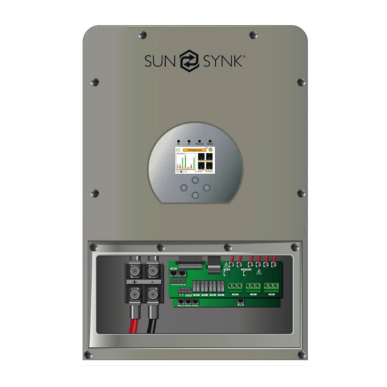
Hybrid Parity (Super) Inverter
INSTALLER MANUAL
3.6kW/5.5kW/8.8kW PLUS PARALLEL VERSION
Global Tech China Ltd, 3 Floor, Wai Yip Industrial Building.171 Wai Yip Street,
Kwun Tong, Kowloon, Hong Kong.
Tel: +852 2884 4318 Fax: +8522884 4816
www.sunsynk.com / sales@globaltech-china.com / www.globaltechhk.com
Advertisement
Table of Contents

Related Manuals for SunSynk SUN-3.6K-SG01/03LP1-EU


Summary of Contents for SunSynk SUN-3.6K-SG01/03LP1-EU
- Page 1 Hybrid Parity (Super) Inverter INSTALLER MANUAL 3.6kW/5.5kW/8.8kW PLUS PARALLEL VERSION Global Tech China Ltd, 3 Floor, Wai Yip Industrial Building.171 Wai Yip Street, Kwun Tong, Kowloon, Hong Kong. Tel: +852 2884 4318 Fax: +8522884 4816 www.sunsynk.com / sales@globaltech-china.com / www.globaltechhk.com...
-
Page 2: Table Of Contents
Index 1. SAFETY ..............................4 ..........................5 1.1. S YSTEM VERVIEW 2. TECHNICAL SPECIFICATION ......................7 ..........................9 2.1. S YSTEM IAGRAM 3. INSTALLATION ..........................10 ......................10 3.1. S ELECTING THE MOUNTING AREA ........................11 3.2. M OUNTING THE INVERTER ........................12 3.3. B ATTERY ONNECTION ...................... -
Page 4: Safety
1. SAFETY WARNING !!! HIGH LIFE RISK DUE TO FIRE OR ELECTROCUTION. The Sunsynk Parity Hybrid Inverter can only be installed by a qualified licensed electrical contractor. This is not a DIY product. Be sure to read this manual thoroughly before installation. -
Page 5: System Overview
15. Ground connection 16. Data logger The Sunsynk Hybrid Parity Inverter is a highly efficient power management tool that allows the user to hit those ‘parity’ targets by managing power flow from multiple sources such as solar, main electrical grids, and generator, and then effectively storing and releasing electric power as the utilities require. - Page 6 SECURE Overload/over-temperature/short-circuit protection Smart battery charger design for optimized battery protection Limiting function installed to prevent excess power overflow to grid APPLICATIONS Marine (vessel power management) Power shedding (home/office/factory) UPS (fuel-saving systems) ...
-
Page 7: Technical Specification
2. TECHNICAL SPECIFICATION SUN-3.6K-SG01/03LP1-EU and SUN-5K-SG01/03LP1-EU Model SUN-3.6K-SG01/03LP1-EU SUN-5K-SG01/03LP1-EU Battery Input Data Battery Type Lead-acid or Lithium-ion Battery Voltage Range (V) 40~60V Max. Charging Current (A) 120A Max. Discharging Current (A) 120A Charging Curve 3 Stages/Equalisation External Temperature Sensor... - Page 8 SUN-5K-SG01LP1-US, SUN-6K-SG01LP1-US, SUN-7.6K-SG01LP1-US/EU, SUN-8K-SG01LP1-US/EU SUN-5K- SUN-6K- SUN-7.6K- SUN-8K- Model SG01LP1-US SG01LP1-US SG01LP1-US/EU SG01LP1-US/EU Battery Input Data Battery Type Lead-acid or Lithium-ion Battery Voltage Range (V) 40~60V Max. Charging Current (A) 120A 135A 190A 190A Max. Discharging Current (A)
-
Page 9: System Diagram
Weight (kg) Size (Length x Width x Height) 670 x 420 x 233 mm Protection Degree IP65 Installation Style Wall-mounted Warranty 5 years 2.1. System Diagram Hybrid Parity (Super) Inverter 3.6kW/5.5kW/8.8kW Plus Parallel Version... -
Page 10: Installation
3. INSTALLATION 3.1. Selecting the mounting area DO NOT install the inverter in the following areas: Areas with high salt content, such as the marine environment. It will deteriorate metal parts, causing the parts to fail or the unit to leak water. -
Page 11: Mounting The Inverter
Even if they are installed more than 1m apart, it is still possible to receive noise under some signal conditions. If children under 10 years old may approach the unit, take preventive measures so that they cannot reach and touch the unit. -
Page 12: Battery Connection
Risk of injury when lifting and from falling inverter Remember that this inverter is heavy (See section 2 “Technical Data”)! Please be careful when removing the inverter from the packaging and mounting it onto the wall. 3.3. Battery Connection ... -
Page 13: Connecting A Lithium Battery
Before making the final DC connection or closing the DC breaker/disconnection device, ensure that the inverter is wired properly. Reverse polarity connection on the battery will damage the inverter. Recommended DC Surge Protector: 3.3.1 Connecting a Lithium Battery When connecting a Lithium battery, follow the connection steps bellow and then check section 4.13 “Setting Up a Lithium Battery”... -
Page 14: Ac Connection - Single Inverter Or Multi Inverter System
3.4. AC Connection – Single Inverter or Multi Inverter System All wiring and cable sizing must be following the country wiring regulations and code of practices. Ensure that suitable disconnection devices and RCDs are fitted. NOTES Depending on the battery type, the inverter should be capable of controlling the batteries BMS. - Page 15 GEN/AUX Connection for a generator This works like a conventional grid-tied inverter. It is both an in and out GRID connection for non-essential load and supply Connection of essential loads such as lighting, security systems, and LOAD internet Recommended AC Surge Protector Please ensure you use suitable protection devices.
-
Page 16: Installing The Ct Coil
3.5. Installing the CT Coil The CT coil is one of the most important parts of the Sunsynk Parity inverter. This device reduces the power of the inverter to prevent feeding power to the grid. This feature is also known as "Zero Export". - Page 17 IMPORTANT !!! See below for information to determine if the CT coil is connected the correct way around: 1. First of all, ensure that the CT is measuring some power flowing into the house/inverter by switching off the "Time Of Use" setting and disconnecting the PV panels.
-
Page 18: Connecting The Pv
3.5. Connecting the PV The inverter has two built-in MPPT controllers, MPPT 1 and MPPT 2, which can connect two arrays of photovoltaic panels in parallel with a maximum current of 18 Amp (as shown below). Before connecting to PV modules, install a separate DC circuit breaker between the inverter and PV modules. -
Page 19: Operation
4. OPERATION 4.1. Display LED indicator Meaning Green LED solid light PV connection normal Green LED solid light Grid connection normal Normal Green LED solid light Inverter functioning normally Alarm Red LED solid light Fault Function Key Description To exit the previous mode... -
Page 20: Switching On/Off
4.2. Switching ON/OFF Once the inverter has been properly installed and the batteries are connected, press the on/off button (located on the left side of the case) to turn-on the system. When the system is connected without a battery but connected with either PV or grid and the on/off button is switched off, the LCD will still light up (display will show off). -
Page 21: Status Page
4.4. Status Page To access the Status page, click on the “Battery” or “AC Load” dial on the Home page. What this page displays: Total solar power produced MPPT 1 power/voltage/current MPPT 2 power/voltage/current Grid power ... -
Page 22: System Flow Page
4.5. System Flow Page Access by clicking on the “Bar Chart ” on the home page What this page displays: The system flow. MPPTs power. Battery status. Power distribution to load or grid. To better understand the functioning of your system, take a look at the figure bellow: 1. -
Page 23: Setup Page
4.6. Setup Page To access the Setup page click on the gear icon on the right top of the navigation menu. What this page displays: Serial number. Software version. Time, Date, and MCU. What you can do from this page: ... -
Page 24: Set Company Name / Beeper / Auto Dim
4.8. Set Company Name / Beeper / Auto dim To set company name click on the “Basic“ icon and then on “Display”. What this page displays: Beeper status (ON/OFF). Installers names. What you can do from this page: ... -
Page 25: Factory Reset And Lock Code
4.9. Factory reset and Lock Code To set time click on the “Basic“ icon and then on “Reset”. What this page displays: Reset status. Whether lock code is used or not. What you can do from this page: ... -
Page 26: Generator And Battery Page
Use battery SOC for all settings (%). No battery: tick this box if no battery is connected to the system. BMS setting. Active battery - This feature will help recover a battery that is 100% discharged by slowly changing from the solar array. -
Page 27: Battery Discharge Page
Shutdown causes the inverter to enter standby mode. It will not completely shut down the inverter. The total shutdown is below 19V. The voltage displayed on the Sunsynk Parity Inverter will vary depending on whether the inverter is charging or discharging the batteries. -
Page 28: Setting Up A Lithium Battery
State of Charge Bulk: Involves about 80% of the recharge in which the charger current is held constant (in a constant current charger), and voltage increases. The properly sized charger will give the battery as much current as it will accept up to charger capacity (25% of battery capacity in Amp hours) Absorption: Remaining charge equals 20%, approximately. - Page 29 NOTE Some types of lithium battery the BMS cannot be controlled by Sunsynk inverter. In this case, treat the battery as a lead-acid type and set the charging and discharging protocol following the battery manufacturer specification.
-
Page 30: Program Charge / Discharge Times Page
IMPORTANT When not using communications between battery and inverter, never overcharge your battery bank concerning current and voltage. Many lithium batteries are limited to 100A, some are lower and some are higher. Ensure that voltage and current specifications provided by the battery manufacturer are followed. - Page 31 Concerning the detailed figure above: 1. Tick this box to do not export power back to the grid (the CT coil will detect power flowing back to the grid and will reduce the power of the inverter only to supply the local load).
-
Page 32: Grid Supply Voltage And Frequency - Grid Supply Page
Example: This is a zero export power to the grid example. Power is supplying the non-essential load and maximum power of the inverter is set as 8kW. The inverter is connected to the grid, but no export is performed. It allows small amounts of power to flow from the grid (set as 100W in this case) to prevent any backflow. -
Page 33: Advanced Settings For Paralleling Inverters
Set the Modbus SN for paralleling The Sunsynk parity inverter can be wired standalone or where more power is required it can be connected in parallel either single or 3 phase configuration. The maximum number of 8.8kW inverters that can be paralleled in a single phase utility grid is three (26.4kW) and the maximum number that can be paralleled... - Page 34 IMPORTANT Be careful with bus bar sizes. The CT coils used to limit export power must only be connected to the master. Therefore, if six inverters are paralleled, three CT coils will be required. Connect a RJ45 communication cable between each inverter; the order is not important since both sockets are the same, so there is no IN or OUT.
- Page 35 If you need further help please refer to the Sunsynk website where you will find training videos and frequently asked questions www.sunsynk.com. From here you can also update the inverter operating system if required, but generally, if the inverter is working fine we recommend do not upgrade...
-
Page 36: Solar Power Generated
4.17. Solar Power Generated This page shows the daily, monthly, yearly, and total solar power produced. Access this page by clicking on the “Solar/Turbine” icon on the home page. 4.18. Grid Power This page shows the daily, monthly, yearly, and total grid power export or consumed. Access this page by clicking on the “Solar/Turbine”... -
Page 37: Advanced Settings For Wind Turbine
4.19. Advanced Settings for Wind Turbine To configure wind turbine settings click on the “Advance” icon. What this page displays: If one or both of the MPPTs are connected to a wind turbine. What you can do from this page: ... -
Page 38: Advanced Settings For Auxiliary Load
Most wind turbines are three-phase PM type. Therefore, either a wind turbine controller or a direct connection to the MPPT via a simple protection circuit will be required. Dump Load: When the battery (battery bank) is fully charged and the water turbine/wind turbine/solar module is still generating power, a dump load will provide the electricity a path to flow. - Page 39 A nice feature is when the batteries are fully charged and the inverter is still producing energy from the PV or the turbine it is possible to direct the energy to another load such as a water heater. Aux Load off Battery % or...
-
Page 40: Advanced Settings For Peak Power Shaving
4.21. Advanced Settings for Peak Power Shaving To configure auxiliary load (previously known as smart load) settings click on the “Aux Load” icon. What this page displays: Generator peak shaving is ON or OFF. Grid peak shaving is ON or OFF. -
Page 41: Fault Codes
Solutions Inverter work mode changed Working Mode Change 1. Reset the inverter. 2. Seek help from Sunsynk. AC Slide over current fault. 1. Check if the backup load power is AC over current fault or hardware within the range of the inverter. - Page 42 2. You may have a faulty PV panel (earth short) 3. Restart inverter PV isolation resistance is too low 1. Check if the connection of PV panels DC insulation impedance failure and inverter are firmly connected. 2. Check if the earth bond cable on inverters is connected to the ground.
- Page 43 Heat Sink temp is too high 1. Check if the working environment Heat sink high-temperature failure temperature is too high. 2. Turn off the inverter for 30 minutes and restart.
- Page 44 Section 4 “Technical Specification”. If you need further help please refer to the Sunsynk website where you will find training videos and frequently asked questions www.sunsynk.com. Hybrid Parity (Super) Inverter 3.6kW/5.5kW/8.8kW Plus Parallel Version...
- Page 45 Global Tech China Ltd, 3 Floor, Wai Yip Industrial Building.171 Wai Yip Street, Kwun Tong, Kowloon, Hong Kong. Tel: +852 2884 4318 Fax: +8522884 4816 www.sunsynk.com / sales@globaltech-china.com / www.globaltechhk.com Hybrid Parity (Super) Inverter 3.6kW/5.5kW/8.8kW Plus Parallel Version...
Need help?
Do you have a question about the SUN-3.6K-SG01/03LP1-EU and is the answer not in the manual?
Questions and answers