Table of Contents
Advertisement
SINGLE-PHASE
HYBRID INVERTER
USER MANUAL
SUNSYNK-3.6K-SG01LP1 / SUNSYNK-3.6K-SG03LP1 /
SUNSYNK-5K-SG01LP1 / SUNSYNK-5K-SG03LP1
Global Tech China Ltd, 3 Floor, Wai Yip Industrial Building.
171 Wai Yip Street, Kwun Tong, Kowloon, Hong Kong.
Tel: +852 2884 4318 Fax: +8522884 4816
www.sunsynk.com / sales@sunsynk.com
PLEASE RETAIN FOR
v.26 (04/27/23
FUTURE REFERENCE
Advertisement
Table of Contents

Related Manuals for SunSynk SUNSYNK-3.6K-SG01LP1


Summary of Contents for SunSynk SUNSYNK-3.6K-SG01LP1
- Page 1 SINGLE-PHASE HYBRID INVERTER USER MANUAL SUNSYNK-3.6K-SG01LP1 / SUNSYNK-3.6K-SG03LP1 / SUNSYNK-5K-SG01LP1 / SUNSYNK-5K-SG03LP1 Global Tech China Ltd, 3 Floor, Wai Yip Industrial Building. 171 Wai Yip Street, Kwun Tong, Kowloon, Hong Kong. Tel: +852 2884 4318 Fax: +8522884 4816 www.sunsynk.com / sales@sunsynk.com PLEASE RETAIN FOR v.26 (04/27/23...
-
Page 2: Table Of Contents
Table of Contents SAFETY 1. 1.1. General Safety 1.2. Symbols 1.3. Safety Instructions 1.4. Disposal 2. PRODUCT INTRODUCTION 2.1. Product Overview 2.2. Product Size 2.3. Product Features 2.4. Basic System Architecture 3. TECHNICAL SPECIFICATIONS 4. INSTALLATION 4.1. Parts List 4.2. Selecting the Mounting Area 4.3. Mounting the Inverter 4.4. Battery Connection 4.4.1. Function port definition 4.4.2. Recommended DC Battery Protection 4.5. Connecting a Lithium Battery 4.6. Temperature Sensor Connection for Lead-Acid Battery 4.7. Connecting the AC... - Page 3 5. OPERATION 5.1. Switching ON/OFF 5.2. Display 5.2.1. LED indicators 5.2.2. Function buttons 5.3. LCD operation flow chart 5.4. Home page 5.5. Status Page 5.6. System Flow Page 5.7. Setup Page 5.8. Basic Setup 5.8.1. Set Time (Clock) 5.8.2. Set Company Name / Beeper / Auto dim 5.8.3. Factory Reset and Lock Code 5.9. Battery Setup Page 5.10. Generator &...
- Page 4 8. COMMISSIONING 8.1. Start-Up / Shutdown Procedure 8.2. Information for Commissioning the Inverter 8.3. GDFI Fault 9. MAINTENANCE APPENDIX A APPENDIX B APPENDIX C APPENDIX D APPENDIX E SINGLE PHASE HI 3.6/5kW | User Manual...
-
Page 5: Safety
1. SAFETY 1.1. General Safety This device should only be used in accordance with the instructions within this manual and in compli- ƒ ance with local, regional, and national laws and regulations. Only allow this device to be installed, oper- ated, maintained, and repaired by other people who have read and understood this manual. Ensure the manual is included with this device should it be passed to a third party. -
Page 6: Safety Instructions
WARNING HIGH LIFE RISK DUE TO FIRE OR ELECTROCUTION. Sunsynk Single-Phase Hybrid Inverter can only be installed by a qualified licensed electrical contractor. This is not a DIY product. This chapter contains important safety and operating instructions. Read and keep this manual for future ƒ... -
Page 7: Product Introduction
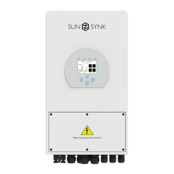
2. PRODUCT INTRODUCTION This multifunctional inverter combines the functions of an inverter, solar charger and battery charger to offer uninterruptible power support with a portable size. Its comprehensive LCD display offers user-configurable and easily accessible button operations such as battery charging, AC/solar charging, and acceptable input voltage based on different applications. -
Page 8: Product Size
2.2. Product Size Inverter Size Mounting bracket SINGLE PHASE HI 3.6/5kW | User Manual... -
Page 9: Product Features
2.3. Product Features INTERACTIVE Easy and simple to understand display ƒ Supporting Wi-Fi or GSM monitoring ƒ Visual power flow screen ƒ Smart settable 3-stage MPPT charging for optimized battery performance ƒ Auxiliary load function ƒ Parallel / multi invert function grid-tied and off-grid ƒ... -
Page 10: Basic System Architecture
2.4. Basic System Architecture The following illustration shows the basic application of this inverter. It also includes the following devices to have a Complete running system. Generator or Utility ƒ PV modules ƒ Consult with your system integrator for other possible system architectures depending on your requirements. -
Page 11: Technical Specifications
3. TECHNICAL SPECIFICATIONS Model SUNSYNK-3.6K-SG01LP1 / SUNSYNK-3.6K-SG03LP1 Product Type Hybrid Inverter Enclosure IP65 Ambient Temperature -45ºC ~ 60ºC (>45ºC derating) Protection Level Class I Charge Mode Battery Voltage 48Vd.c (40Vd.c ~ 60Vd.c) Battery Current 90Ad.c (max.) AC Input Voltage L/N/PE 220/230Va.c... - Page 12 Model SUNSYNK-5K-SG01LP1 / SUNSYNK-5K-SG03LP1 Product Type Hybrid Inverter Enclosure IP65 Ambient Temperature -45ºC ~ 60ºC (>45ºC derating) Protection Level Class I Charge Mode Battery Voltage 48Vd.c (40Vd.c ~ 60Vd.c) Battery Current 120Ad.c (max.) AC Input Voltage L/N/PE 220/230Va.c AC Input Frequency...
-
Page 13: Installation
4. INSTALLATION 4.1. Parts List Check the equipment before installation. Please make sure nothing is damaged in the package. You should have received the items in the following package: Parallel communication cable x1 Datalogger x1 SINGLE PHASE HI 3.6/5kW | User Manual... -
Page 14: Selecting The Mounting Area
4.2. Selecting the Mounting Area This Hybrid inverter is designed for outdoor use(IP65), DO NOT install the inverter in the following areas: Areas with high salt content, such as the marine environment. It will deteriorate the metal parts and ƒ possibly lead to water/dampness penetrating the unit. Areas filled with mineral oil or containing splashed oil or steam, such as those found in kitchens. -
Page 15: Mounting The Inverter
Install the indoor unit on the wall where the floor height is higher than 1600mm. ƒ For proper heat dissipation, allow a clearance of approximately 500mm to the side, 500mm above and ƒ below the unit, and 1000mm to the front of the unit. WARNING For proper air circulation to dissipate heat, allow a clearance of approx. -
Page 16: Battery Connection
Inverter Hanging plate installation Inverter hanging plate installation 4.4. Battery Connection For safe operation and compliance, a separate DC over-current protector or disconnect device is required between the battery and the inverter. Switching devices may not be required in some applications, but over-current protectors are still required. - Page 17 CAUTION All wiring/connecting must be performed by qualified personnel. Before making the final DC connection or closing the DC Breaker/disconnection device, ensure the inverter unit is wired correctly. A reverse-polarity connection on the battery will damage the inverter. Please follow the below steps to implement battery connection: Please choose a suitable battery cable with the correct connector which can well fit into the battery ƒ...
-
Page 18: Function Port Definition
4.4.1. Function port definition DIP Switch Inverter BMS 485 BMS CAN DRMs HM G-V G-S ATS240V parallel_1 parallel_2RS 485 240V Coil Neutral Earth Bond Batt Temp Gen start-up Sensor N/O Relay CT Coil port. coil relay open contact GV/GS (diesel generator startup signal) SINGLE PHASE HI 3.6/5kW | User Manual... -
Page 19: Recommended Dc Battery Protection
4.4.2. Recommended DC Battery Protection Inverter DC Isolator Fuses Two Pole 4.5. Connecting a Lithium Battery When connecting a Lithium battery, follow the connection steps below and check ‘Setting up a Lithium Battery’ to connect with an inverter. 1. Connect the correct cable diameter following the battery manufacture specifications and recommended safety devices. - Page 20 PLEASE NOTE When connecting more than one battery, ensure they are set in the configuration of ‘master and slave’. PLEASE NOTE Depending on the battery type, the inverter should be capable of controlling the batteries BMS. Therefore, you need to set the protocol of the BMS on both the battery and the inverter. When using more than one battery, the first battery will be the master, and the other batteries will be the slaves.
-
Page 21: Temperature Sensor Connection For Lead-Acid Battery
4.6. Temperature Sensor Connection for Lead-Acid Battery Temp. sensor SINGLE PHASE HI 3.6/5kW | User Manual... -
Page 22: Connecting The Ac
4.7. Connecting the AC Before connecting to the grid, please install a separate AC breaker between the inverter and the grid. Also, it is recommended that installs an AC breaker between the backup load and inverter. This will ensure that the inverter can be securely disconnected during maintenance and fully protected from overcurrent. For the 3.6/5KW model, the recommended AC breaker for backup load is 32A/40A. -
Page 23: Recommended Ac Surge Protector
GEN PORT LOAD GRID GEN PORT LOAD GRID 4.7.1. Recommended AC Surge Protector SINGLE PHASE HI 3.6/5kW | User Manual... -
Page 24: Pv Connection
4.8. PV Connection Before connecting to PV modules, please install a separate DC circuit breaker between the inverter and PV modules. It is very important for system safety and efficient operation to use appropriate cable for PV mod- ule connection. To reduce the risk of injury, please use the proper recommended cable size as below. Model Wire Size Cable (mm... -
Page 25: Pv Protection
4.9. Installing the CT Coil The CT coil is one of the most important parts of the Sunsynk Parity inverter. This device reduces the power of the inverter to prevent feeding power to the grid. This feature is also known as “Zero Export”. - Page 26 L N PE L N PE L N PE Load Grid Inverter White wire Black wire Arrow pointing Grid inverter If the CT coil is fitted in the wrong way then this variable will have negative instead of positive values when the power is flowing into the house/inverter.
-
Page 27: Meter Connection
4.10. Meter Connection 4.10.1. System Connection for the CHNT Meter Grid Load RS485 Inverter Breaker Meter_CON Parallel_AParallel_B System connection diagram for the CHNT meter Grid Grid input Output RS 485 DDSU666 DIN-RAIL METER RS485A 230V 5(60) A 800imp/kWh RS485B CHNT DDSU666 CHINT meter 4.11. Earth Connection (MANDATORY) An Earth Cable shall be connected to the earth plate on the grid size in order to prevent electric shock if the original protective conductor fails. - Page 28 Since the inverter is a true hybrid, then the bond must only be made when the inverter is operating in Islanding Mode. To accommodate this, Sunsynk provides an AC output, which is connected to the A/T/S connections whenever the inverter is running on Island Mode. Therefore, you can simply connect the coil of an AC relay to the ATS 240 connections.
-
Page 29: Wiring System For Inverter
4.12. Wiring System for Inverter This diagram is an example for grid systems without special requirements on electrical wiring connection. Note: The back-up PE line and earthing bar must be grounded properly and DC Breaker effectively. Otherwise the back-up function may be abnormal when the grid fails. AC Breaker Load Battery... -
Page 30: Typical Application Diagram Of Diesel Generator
4.13. Typical Application Diagram of Diesel Generator (Region:EU) L wire N wire PE wire GV/GS: dry contact signal for startup the diesel generator. When the "GEN signal" is active, the open contact (GV/GS) will switch on (no voltage output). If the "Signal ISLAND MODE "is ticked, the GS port will be the dry contact signal for startup HM G-V G-S ATS240V... -
Page 31: Single-Phase Parallel Connection Diagram
4.14. Single-Phase Parallel Connection Diagram L wire N wire PE wire Inverter No.3 (slave) L N PE L N PE L N PE BMS 485 BMS CAN DRMs Load Grid Ground parallel_1 parallel_2RS485 Inverter Inverter Breaker No.2 L N PE L N PE L N PE (slave) Load... -
Page 32: Three-Phase Parallel Inverter
4.15. Three-Phase Parallel Inverter SINGLE PHASE HI 3.6/5kW | User Manual... -
Page 33: Operation
5. OPERATION 5.1. Switching ON/OFF Once the inverter has been correctly installed and the batteries have been connected, press the ON/OFF button (located on the left side of the case) to activate the system. When the system is connected without a battery but connected with either PV or grid and the ON/OFF button is switched off, the LCD will still illumi- nate (display will show off). -
Page 34: Lcd Operation Flow Chart
5.3. LCD operation flow chart Solar Page Solar Graph Grid Page Grid Graph Inverter Page Battery Page BMS Page HOME PAGE Load Page Load Graph Basic Setting Battery Settings Grid Settings System Mode System Setup Advanced Settings Aux Load Settings Fault Codes Li BMS Settings SINGLE PHASE HI 3.6/5kW | User Manual... -
Page 35: Home Page
5.4. Home page Press the Esc button any page to access the home page: 1. Customer name 2. Access the settings menu page 3. Access solar page 4. Access load page 5. Access battery page SOLAR/TURBINE AC load 6. Access grid page 7. -
Page 36: System Flow Page
What this page displays: Total solar power produced. Inverter voltage. ƒ ƒ MPPT 1 power/voltage/current. Inverter current. ƒ ƒ MPPT 2 power/voltage/current. Load power. ƒ ƒ Grid power. Load voltage. ƒ ƒ Grid frequency. Battery power charge/discharge. ƒ ƒ Grid voltage. Battery SOC. -
Page 37: Setup Page
What this page displays: The system flow. Battery status. ƒ ƒ MPPTs power. Power distribution to load or grid. ƒ ƒ 5.7. Setup Page To access Settings, click on the gear icon on the right top of the navigation menu. What this page displays: Serial number. -
Page 38: Basic Setup
5.8. Basic Setup 5.8.1. Set Time (Clock) To set time, click on the BASIC icon and then on ‘Time’ What this page displays: Time. ƒ Date. ƒ AM/PM. ƒ What you can do from this page: Adjust / set time. ƒ Adjust / set date. ƒ... -
Page 39: Factory Reset And Lock Code
How to set the auto dim: Set a number in the auto dim box to dim the LCD after a number of seconds. How to turn the beep on or off: Check or uncheck the beep box and the press OK to configure it as you prefer. -
Page 40: Battery Setup Page
5.9. Battery Setup Page To configure battery settings, click on the BATTERY icon and then on ‘Batt type’. What this page displays: Battery capacity in (Ah): For non-BMS-batteries the range allowed is 0-2000Ah, while for lithium-ion, ƒ the inverter will use the capacity value of the BMS. Charge/Discharge Amps: The Max battery charge/discharge current (0-90A for 3.6KW model, 0-120A ƒ... -
Page 41: Generator & Battery Page
5.10. Generator & Battery Page To configure battery charging settings, click on the BATTERY icon and then on ‘Batt Charge’. What this page displays: Start: Generator start voltage/SOC %. S.O.C at 30% system will AutoStart a connected generator to ƒ charge the battery bank. Amps: Charge rate of 40A from the attached generator in Amps. - Page 42 1Amp 12V. Below is a simple reference circuit of an auto-start system that can auto-start generators on a boat. (Sunsynk will be releasing a new OS E406 ( Auto-Start ) for better generator control).
-
Page 43: Battery Discharge Page
5.11. Battery Discharge Page To configure inverter’s shut-down settings, click on the BATTERY icon and then on ‘Shut Down’. SINGLE PHASE HI 3.6/5kW | User Manual... - Page 44 Activating Shutdown causes the inverter to enter standby-mode. It does not entirely shut down the inverter. Total shutdown occurs at voltages below 19V. The voltage displayed on the Sunsynk Parity Inverter will vary depending on whether the inverter is charging or discharging the batteries.
-
Page 45: Setting Up A Lithium Battery
Absorption: To fully charge a battery, a period of charging at a relatively high voltage is needed. This period of the charging process is called absorption. This occurs when the charging of a battery has reached 80% of its capacity. The remaining charge equals 20% approximately. It makes the charger hold the voltage at the charger’s absorption voltage (between 14.1 VDC and 14.8 VDC, depending on charger set points) and decreases the current until the battery is fully charged. - Page 46 PLEASE NOTE With some types of lithium batteries, the BMS cannot be controlled by the Sunsynk inverter. In this case, treat the battery as a lead-acid type and set the charging and discharging protocol following the battery manufacturer's specifications.
- Page 47 SACRED SUN FCIFP48100A RS485 Cut Line 3, 6, 8 SSIFP48100A RS485 SS4074 To be used with V2 Logger http://solarmd.co.za/invert- SolarMD SS4037 er-compatibility-solarmd/ SS202 sunsynk-and-solar-md/ SHOTO SDC-Box5(5.12KWH) L051100-A L051100-A1 UZ ENERGY L051100-B L051100-D ESS-5120 RS485 ESS-10240 RS485 ESS-BOX2...
- Page 48 RS485 Inverter Brand Model Storage Notes or CAN Setup Inverter IPACK C3.3 DOWELL IPACK C6.5 IPACK C10 G2500-48V Giter G5040-48V CFE2400 CF Energy CFE5100 CFE5100S Batterich/ UP3686 Greenrich BYD Battery-Box LV Flex Lite 48NPFC80 RS485 RJ45 Pin 1: GND RJ45 Pin 2: RS485_A 48NPFC100 RS485...
- Page 49 RS485 Inverter Brand Model Storage Notes or CAN Setup Inverter U-P48200-7 U-P48100-7 U-P48150-1 L01-48100 DMEGC L02-48200 LR48100 Robuste LR48200 4K Pack Soluna 5K Pack EOS-5K Pack REVOV R100 Powerfree Rack PAND Powerfree Cube CLiS (Zhong- neng Lithi- um Battery Enerhi-M Series Technology Taizhou Co., Ltd.)
- Page 50 RS485 Inverter Brand Model Storage Notes or CAN Setup Inverter LM-JW-51.2V100Ah LEMAX LM-JW-51.2V200Ah EVO 5.7KWH 48V-120Ah Yoshopo BB-LFP-100Ah-P Gen2 P48200-7 GEN2 Gen2 P48100-7 Gen2 P48150-1 51.2V 100Ah Shanghai Green GTEM-48V2500 RS485 Tech Co.,Ltd. Unipower UPI.FP4845 RS485 LD-100P210J RS485 LPBF Series RS485 Felicity LPBA-OL Series...
-
Page 51: Program Charge & Discharge Times
PLEASE NOTE When communications between the battery and inverter do not exist, do not overcharge your battery bank (current or voltage). Many lithium batteries are limited to 100A, some are lower, and some are higher. Ensure that voltage and current specifications provided by the battery manufacturer are followed. - Page 52 Zero Export + Limit To Load Only: The hybrid inverter will only provide power to the backup load connect- ed. The hybrid inverter will neither provide power to the home load nor sell power to the grid. The built-in CT will detect power flowing back to the grid and will reduce the power of the inverter only to supply the local load and charge the battery.
- Page 53 Concerning the detailed next figures: 1. Tick this box to not export power back to the grid (the CT coil will detect power flowing back to the grid and will reduce the power of the inverter only to supply the local load). 2.
- Page 54 Example: This example shows the battery being charged up to 100% by both the Grid and Solar PV from 8 a.m. to 11 a.m. and then being able to supply up to 4kW of battery-power to the ‘essential’ loads from the ‘Load’ Port until the battery SOC drops to 50%.
-
Page 55: Grid Supply Page
Example: During 01:00-05:00, when the battery SOC is lower than 80%, it will use the grid to charge the battery until the battery SOC reaches 80%. During 05:00-08:00 and 08:00-10:00, when battery SOC is higher than 40%, the hybrid inverter will discharge the battery until the SOC reaches 40%. - Page 56 What this page displays: Normal connect: The allowed grid voltage/frequency range when the inverter first time connects to the ƒ grid. Normal Ramp rate: It is the startup power ramp. ƒ Reconnect after trip: The allowed grid voltage/frequency range for the inverter connects the grid after ƒ...
- Page 57 What this page displays: FW: This series inverter is able to adjust inverter output power according to grid frequency. ƒ Droop f: The percentage of nominal power per Hz. ƒ For example: “Start freq f>50.2Hz, Stop freq f<50.2, Droop f=40%PE/Hz” when the grid frequency reaches 50.2Hz, the inverter will decrease its active power at Droop f of 40%.
- Page 58 What this page displays: P(Q): It adjusts the inverter reactive power according to the set active power. P(PF): It adjusts the inverter PF according to the set active power. Lock-in/Pn 50%: When the inverter output active power is less than 50% rated power, it won't enter the P(PF) mode.
-
Page 59: Advanced Settings For Paralleling Inverters
Set the Modbus SN for paralleling. The Sunsynk parity inverter can be wired standalone or where more power is required it can be connected in parallel either single or 3 phase configuration. The maximum number of inverters that can be paral- leled in a single phase utility grid is 16 and the maximum number that can be paralleled in a three phase utility grid is 15A. - Page 60 Each invert will require a fuse isolator with surge protection and each group circuit will require an RCD. If the batteries as supplying power to the main load during the outage then a change over switch will also be required or a split load can be used. The CT coils used to limit export power must only be connected to the master.
- Page 61 If you need further help please refer to the Sunsynk website where you will find training videos and Fre- quently Asked Questions www.sunsynk.com. Firmware prior installation is important to be updated and all inverters in parallel or three phase system must be the same.
-
Page 62: Connecting The Drm's
5.16. Connecting the DRM’s This can be selected under advance settings. This can be selected under advance settings. 1. DRM 1/5 5. Ref 0 2. DRM 2/6 6. D Ground 3. DRM 3/7 7. Net J 4-7 4. RDRM 4/8 8. Net J 4-7 SINGLE PHASE HI 3.6/5kW | User Manual... -
Page 63: Advanced Function Setup
5.17. Advanced Function Setup System selfcheck: Disable. this is only for the factory. Signal ISLAND MODE: When "signal island mode" is checked and the inverter connects the grid, the ATS port voltage will be 0. When "signal island mode" is checked and the inverter is disconnect- ed from the grid, the ATS port voltage will output 230Vac. -
Page 64: Grid Power
5.19. Grid Power This page shows the Daily / Monthly / Yearly and total grid power export or consumed. Access this page by clicking on the ‘Solar/Turbine’ icon on the home page. TOTAL TOTAL SINGLE PHASE HI 3.6/5kW | User Manual... -
Page 65: Advanced Settings For Wind Turbines
5.20. Advanced Settings for Wind Turbines To configure wind turbine settings, click on the ADVANCE icon. What this page displays: If one or both of the MPPTs are connected to a wind turbine. ƒ What you can do from this page: Select the MPPT to be used as a turbine input. -
Page 66: Advanced Settings For Auxiliary Load
Most wind turbines are three-phase PM type. Therefore, either a wind turbine controller or a direct connec- tion to the MPPT via a simple protection circuit will be required. Dump Load or Diversion Load is an important part of an off-grid power system. When the battery ( Battery Bank ) is fully charged, and the water turbine / wind turbine / solar PV module is still generating, a dump load is a useful device to send spare electricity to. - Page 67 For Gen Input mode: Gen Input: Tick this box if using a Generator. Allowed Max. power from diesel generator. Peak shaving power: This is a technique used to reduce electrical power consumption during periods of maximum demand on the utility grid. This enables the user to save substantial amounts of money due to the expensive peak power charges.
- Page 68 On Grid always on: When click "on Grid always on" the smart load will switch on when the grid is present. Solar Power: Power limiter to the maximum power allowed to the Aux load. Aux Load OFF Batt Battery SOC at which the Smart load will switch off. Aux Load ON Batt: Battery SOC at which the Smart load will switch on.
-
Page 69: Operation Modes
6. Operation Modes 6.1. Mode I: Basic AC cable DC cable COM cable Backup Load On-Grid Home Load Solar Battery Grid 6.2. Mode II: Generator AC cable DC cable Solar Backup Load On-Grid Home Load Grid Battery Generator SINGLE PHASE HI 3.6/5kW | User Manual... -
Page 70: Mode Iii: With Aux-Load
6.3. Mode III: With Aux-Load AC cable DC cable COM cable Backup Load On-Grid Home Load Solar Battery Grid 6.4. Mode IV: AC Couple On-Gen+AC couple AC cable DC cable On-Grid Home Load Grid Solar Backup Load Battery On-Grid Inverter SINGLE PHASE HI 3.6/5kW | User Manual... - Page 71 On-Load+AC couple AC cable DC cable On-Grid Inverter Backup Load Solar On-Grid Home Load Battery Grid Smart Load On-Grid+AC couple AC cable DC cable Backup Load Solar On-Grid Home Load On-Grid Inverter Battery Grid Smart Load CAUTION The 1st priority power of the system is always the PV power, then 2nd and 3rd priority power will be the battery bank or grid according to the settings.
-
Page 72: Fault Codes
2. If the fault still exists, please get in touch with us for help. Inverter work mode changed 1.Reset the inverter. Working Mode Change 2.Seek help from Sunsynk. AC Slide over current fault. AC over current fault or 1.Check if the backup load power is within the range of the hardware inverter. - Page 73 Error Code Description Solutions DC side over current fault 1. Check PV module connect and battery connect; 2. When in the off-grid mode, the inverter startup with a big DC over current fault of the power load, and it may report F20. Please reduce the load hardware power connected.;...
- Page 74 Error Code Description Solutions Grid frequency out of range 1.Check if the frequency is in the range of specification AC_OverFreq_Fault 2.You may need to adjust the frequency on the grid set up page. Grid frequency out of range 1. Check the frequency is in the range of specification or not.
- Page 75 Chapter 3, ‘Technical Specifications’. If you need further help please refer to the Sunsynk website where you will find training videos and frequent- ly asked questions www.sunsynk.com.
- Page 76 8. COMMISSIONING 8.1. Start-Up / Shutdown Procedure The inverter must be installed by a qualified / licensed electrical engineer in accordance with the country's wiring regulations. Before switching on, the installation engineer must have completed the Earth Bond, RCD and earth leakage tests, checked that the solar panel Voc voltage does not exceed 480V and checked the battery voltage.
- Page 77 Ensure you are familiar This is the heart of the with this, if you fully under- See section ‘Program system this controller stand the controller you Charge / Discharge Times’ everything will fully appreciate the ca- pabilities of there inverter If paralleling inverters in 3 Phase check you phase If using a wind turbine...
- Page 78 APPENDIX A The following table is the connection on battery side: Protocol Description Pin 1: CAN-H Pin 5: CAN-L Pin 2, 3, 4, 6, 7, 8: NC Pin 1: RS485B Pin 2: RS485A Pin 3, 6: GND RS485 Pin 7: RS485A Pin 8: RS485B Pin 4, 5: NC Pin 3: BMS transmit;...
- Page 79 Instantaneous APPENDIX E The Sunsynk inverter can be connected to the internet, but you need to add a data logger to do this. The inverter is compatible with Solar Man data-loggers, which you can obtain from us with your distributor 1.
- Page 80 Email us: sales@sunsynk.co m Tel# 852-2884-4318 VAT Number: 175669460 HK Address: Unit 702-704, 7/F., Texwood Plaza, 6 How Ming Street, Kwun Tong, Kowloon, Hong Kong. wered by...
Need help?
Do you have a question about the SUNSYNK-3.6K-SG01LP1 and is the answer not in the manual?
Questions and answers