SunSynk SUN-8K-SG04LP3 User Manual
Three-phase hybrid inverter
Hide thumbs
Also See for SUN-8K-SG04LP3:
- Installer manual (72 pages) ,
- User manual (20 pages) ,
- User manual (8 pages)
Table of Contents
Advertisement
THREE-PHASE HYBRID
INVERTER
USER MANUAL
SUN-8K-SG04LP3 / SUN-10K-SG04LP3 / SUN-12K-SG04LP3
Global Tech China Ltd, 3 Floor, Wai Yip Industrial Building.
171 Wai Yip Street, Kwun Tong, Kowloon, Hong Kong.
Tel: +852 2884 4318 Fax: +8522884 4816
www.sunsynk.com / sales@globaltech-china.com
www.globaltechhk.com
v4 (04/27/21)
Version 7.0 (07/27/2021)
Advertisement
Table of Contents

Subscribe to Our Youtube Channel
Related Manuals for SunSynk SUN-8K-SG04LP3


Summary of Contents for SunSynk SUN-8K-SG04LP3
- Page 1 THREE-PHASE HYBRID INVERTER USER MANUAL SUN-8K-SG04LP3 / SUN-10K-SG04LP3 / SUN-12K-SG04LP3 Global Tech China Ltd, 3 Floor, Wai Yip Industrial Building. 171 Wai Yip Street, Kwun Tong, Kowloon, Hong Kong. Tel: +852 2884 4318 Fax: +8522884 4816 www.sunsynk.com / sales@globaltech-china.com www.globaltechhk.com v4 (04/27/21) Version 7.0 (07/27/2021)
- Page 2 All information in this User Guide is based on the latest product information available at the time of printing approval. Sunsynk reserves the right to make changes at any time without notice and without incurring any obligation.
- Page 3 INDEX 1. SAFETY 1.1. G ENERAL AFETY NFORMATION 1.2. S YMBOLS 1.3. S AFETY NSTRUCTIONS 1.4. D ISPOSAL EMARKS 2. PRODUCT INTRODUCTION 2.1. S YSTEM VERVIEW 2.2. D IMENSIONS 2.3. F EATURES 2.4. B ASIC YSTEM RCHITECTURE 3. TECHNICAL SPECIFICATIONS 4.
- Page 4 5.6. S ETUP 5.7. S LOCK 5.8. S OMPANY EEPER UTO DIM 5.9. F ACTORY ESET AND 5.10. B ATTERY ETUP 5.11. G ENERATOR AND ATTERY 5.12. B ATTERY ISCHARGE 5.13. S ETTING ITHIUM ATTERY 5.14. P ROGRAM HARGE ISCHARGE IMES 5.15.
- Page 5 SAFETY 1. SAFETY 1.1. General Safety Information This device should only be used in accordance o instructions within this manual and in compliance with local, regional and national laws and regulations. Only allow this device to be installed, operated, maintained, repaired by other persons who have also read and understood this manual.
- Page 6 1.3. Safety Instructions WARNING HIGH LIFE RISK DUE TO FIRE OR ELECTROCUTION. The Sunsynk Three-Phase Hybrid Inverter can only be installed by a qualified licensed electrical contractor. This is not a DIY product. Be sure to read this manual thoroughly before installation.
- Page 7 PRODUCT INTRODUCTION 2. PRODUCT INTRODUCTION The Sunsynk Three-Phase Hybrid Inverter is a highly efficient power management tool that allows the user to hit those ‘parity’ targets by managing power-flow from multiple sources such as solar, mains power (grid) and generators, and then effectively storing and releasing power as and when utilities require.
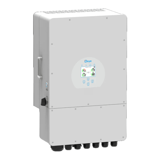
- Page 8 1: Inverter Indicators 7: Meter-485 Port 13: Grid 2: LCD Display 8: Battery Input Connectors 14: Load 3: Function Buttons 9: Function Port 15: Generator Input 4: Power ON/OFF Button 10: Modbus Port 16: Wi-Fi Interface 5: DC Switch 11: BMS Port 6: Parallel Port 12: PV Input with Two MPPT 2.2.
- Page 9 2.3. Features INTERACTIVE Easy and simple to understand LCD display; Supporting Wi-Fi or GSM monitoring; Visual power flow screen; Built-in 2 strings for 1 MPP tracker and 1 string for 1 MPP tracker; Smart settable 3-stage MPPT charging for optimised battery performance; ...
- Page 10 APPLICATIONS Marine (vessel power management); Power shedding (home/office/factory); UPS (fuel-saving systems); Remote locations with solar and wind generators; Building sites; Telecommunication; 2.4. Basic System Architecture The following diagram explains the basic application and architecture of this 3-Phase Inverter.
- Page 11 TECHNICAL SPECIFICATIONS 3. TECHNICAL SPECIFICATIONS Model SUN-8K-SG01LP3 SUN-10K-SG01LP3 SUN-12K-SG01LP3 Battery Input Data Battery Type Lead-acid or Lithium-ion Battery Voltage Range 40~60V Max. Charging Current 190A 210A 240A Max. Discharging Current 190A 210A 240A Charging Curve 3 Stages/Equalization External Temperature Optional Sensor Charging Strategy for Li-Ion Self-adaption to BMS...
- Page 12 Residual Current Monitoring Integrated Unit Output Over Current Integrated Protection Output Shorted Protection Integrated Output Over Voltage Integrated Protection Surge Protection DC Type II / AC Type II Certifications and Standards UL1741, IEEE1547, RULE21, VDE0126, AS4777, NRS2017, Grid Regulation G98,G99, IEC61683, IEC62116, IEC61727 Safety Regulation IEC2109-1, IEC62109-2 EN61000-6-1, EN61000-6-3, FCC 15 Class B...
- Page 13 INSTALLATION 4. INSTALLATION 4.1. Parts List Check if you received all the items listed below. Ensure that nothing is damaged in the package. Page | 13...
- Page 14 4.2. Selecting the Mounting Area For proper heat dissipation, allow a clearance of approximately 500mm to the side, 500mm above and below the unit, and 1000mm to the front of the unit. DO NOT install the inverter in the following areas: Areas with high salt content, such as the marine environment.
- Page 15 Environments where precipitation or humidity are above 95% Areas where the air circulation is too low. ALSO CONSIDER: Installing the indoor unit, outdoor unit, power supply cable, transmission cable, and remote control cable at least 1 metre away from any television or radio receiver. This will prevent TV reception interference or radio noise.
- Page 16 CAUTION Risk of injury (Heavy Object) Remember that this inverter is heavy (45kg) so users must be careful in handling the unit during installation especially when mounting or removing from a wall. Page | 16...
- Page 17 4.4. Battery Connection For safe operation and compliance, an individual DC overcurrent protector or disconnection device is required for the connection of the battery and the inverter. Users are recommended to utilise a suitable fuse and DC isolator (see next page). In some applications, switching devices may not be required, but overcurrent protectors must be used.
- Page 18 4.4.1. Function Ports Definition Page | 18...
- Page 19 4.4.2. Temperature Sensor Connection for Lead-Acid Battery Without a remote temperature sensor, lead-acid batteries may undercharge or overcharge depending on the ambient temperature of the installation environment. This may result in a fire hazard. Page | 19...
- Page 20 NOTICE Depending on the battery type, the inverter should be capable of controlling the batteries BMS. Therefore, you need to set the protocol of the BMS on both the battery and the inverter. When using more than one battery, the first battery will be the master, and the other batteries will be the slaves.
- Page 21 CAUTION All wiring and cable sizes must comply with your particular country’s wiring regulations and Codes of Practices Ensure that suitable disconnection devices and RCDs are fitted. Please follow the steps below to implement GRID, LOAD, and GEN port connections: 1) Before making GRID, LOAD, and GEN port connections, make sure to turn off the AC breaker or disconnector first.
- Page 22 NOTICE Appliances such as air conditioners require 2-3 minutes to re-start as they need enough time to balance refrigerant gas inside the circuit. If a power shortage occurs and recovery is made in a short time, it will cause damage to your connected appliances.
- Page 23 4.6. Connecting the CT Coil NOTICE When the inverter is in the off-grid state, the N line needs to be connected to the earth. Page | 23...
- Page 24 Since the inverter is a true hybrid then the bond must only be made when the inverter is operating in Islanding Mode. To accommodate this, Sunsynk provides an AC output, which is connected to the A/T/S connections whenever the inverter is running on Island Mode.
- Page 25 NOTICE The grid power may still be present, but the inverter is not draining power from it since the unit is working in ‘Island Mode’. You can verify if there is a voltage when the inverter is disconnected from the grid by using a simple multimeter.
- Page 26 Inverter Model 10kW 12kW 450V (140V~1000V) PV Input Voltage 140V~800V PV Array MPPT Voltage Range No. of MPP Trackers No. of Strings per MPP Tracker 4.8.2. PV Module Wiring 1) Switch the Grid Supply Main Switch (AC) OFF. 2) Switch the DC isolator OFF. 3) Assemble PV input connector to the inverter.
- Page 27 a) Strip 7mm of the plastic coating off the DC wire and disassemble the connector cap nut. b) Crimp metal terminals with crimping pliers. c) Insert the contact pin into the connector housing until it locks into place. Then screw the cap nut onto the connector housing. Torque to 2.5-3 N.m d) Finally, insert the DC connector into the positive and negative input of the inverter.
- Page 28 4.9. System Wiring for Inverter The following diagram is an example for an application where the neutral connects with the PV in a distribution box. For countries such as Australia, New Zealand, South Africa, etc., please follow local wiring regulations! Page | 28...
- Page 29 4.10. Wiring Diagram home Page | 29...
- Page 30 OPERATION 5. OPERATION 5.1. Display LED indicator Meaning Green LED solid light PV connection normal Green LED solid light Grid connection normal Normal Green LED solid light Inverter functioning normally Alarm Red LED solid light Fault Function Key Description To exit the previous mode Increase the value of a setting Down Decrease the value of a setting...
- Page 31 5.2. Switching ON/OFF Once the inverter has been correctly installed and the batteries have been connected, press the ON/OFF button (located on the left side of the case) to activate the system. When the system is connected without a battery but connected with either PV or grid and the ON/OFF button is switched off, the LCD will still illuminate (display will show off).
- Page 32 5.4. Status Page To access the Status page, click on the BATTERY or AC LOAD dial on the Home page. What this page displays: Total solar power produced. MPPT 1 power/voltage/current. MPPT 2 power/voltage/current. Grid power. Grid frequency.
- Page 33 5.5. System Flow Page Access by clicking on the bar chart on the Home Page. What this page displays: The system flow. MPPTs power. Battery status. Power distribution to load or grid. To better understand the functioning of your system, take a look at the figure bellow: 1.
- Page 34 5.6. Setup Page To access the Settings, click on the gear icon on the right top of the navigation menu. What this page displays: Serial number. Software version. Time, Date, and MCU. What you can do from this page: Access the Basic Setup Page (press the BASIC icon).
- Page 35 5.7. Set Time (Clock) To set time, click on the BASIC icon and then on ‘Time’. What this page displays: Time. Date. AM/PM. What you can do from this page: Adjust / set time. Adjust / set date. ...
- Page 36 How to change the name: Change the letters in each box by moving the arrows up and down and then select OK. This will change the name on the home screen. How set the auto dim: Set a number in the auto dim box to dim the LCD after a number of seconds.
- Page 37 System self-check: Allows the user to conduct a system diagnosis. Test mode (only for engineers): For engineers to conduct tests. 5.10. Battery Setup Page To configure battery settings, click on the BATTERY icon and then on ‘Batt type’. What this page displays: Battery capacity in (Ah) –...
- Page 38 5.11. Generator and Battery Page To configure battery charging settings, click on the BATTERY icon and then on ‘Batt Charge’. What this page displays: Generator start voltage/SOC %. Grid power start voltage/SOC %. Float V is the voltage at which a ...
- Page 39 The current on thee contacts is limited to approximately, 1Amp 12V. Below is a simple reference circuit of an auto start system that can autostart generators on a boat. (Sunsynk will be releasing a new OS E406 ( Auto-Start ) for better generator control)
- Page 40 5.12. Battery Discharge Page To configure inverter’s shutdown settings, click on the BATTERY icon and then on ‘Shut Down’. What this page displays: Inverter shutdown voltage set as either a voltage or %. Inverter low battery warning set as either a voltage or %.
- Page 41 Setting the cut-off higher is better for the batteries. The batteries recommended for use with the Sunsynk systems are AGM Lead Acid or Lithium Battery Banks. (‘AGM’ means Absorbed Glass Matt construction that allows the electrolyte to be suspended new the plate’s active material. In theory, this enhances both the discharge and recharging efficiency.
- Page 42 Absorption: To fully charge a battery a period of charging at a relatively high voltage is needed. This period of the charging process is called absorption. This occurs when the charging of a battery has reached reached 80% of its capacity. The remaining charge equals 20% approximately.
- Page 43 It is important to refer to the manuals that manufacturers produce for their batteries. That way, the chance of errors occurring during installation are greatly reduced. Below there is a list of batteries that has been examined, tested, and approved by Sunsynk. RS485...
- Page 44 SS202 solarmd/sunsynk-and- solar-md/ www.freedomwon.co.z a/storage/2019/09/free Freedom Lite dom-lite-commercial- Freedomwon Commercial 52V installation-manual- and LV Models rev-2-september- 2019.pdf PINS 1&2 must be REVOV and 2 life RS485 Swopped at Battery side. Voltage Base Charge SHOTO settings must be used.
- Page 45 GS10000 RS485 ABOET VISION Group Alpha Float voltage 54.5V Absorption V 55.00V B-LFP51.2V Disable equalisation 100Ah and B- Backbone 0 Days LFP51.2V Shutdown 20% 125Ah Low Batt 35% Restart 50% NOTICE When communications between battery and inverter does not exist, do not overcharge your battery bank (current or voltage).
- Page 46 5.14. Program Charge / Discharge Times To set ‘Charge’ and ‘Discharge’ times, click on the ‘System Mode’ icon after clicking on the gear icon. What this page displays: A setting to prevent the inverter exporting power to the grid - ‘Zero Export’. ...
- Page 47 Concerning the detailed figure above: 1. Tick this box to do not export power back to the grid (the CT coil will detect power flowing back to the grid and will reduce the power of the inverter only to supply the local load).
- Page 48 no export is performed. The unit allows small amounts of power to flow from the Grid (100W Zero Export Power) to prevent any back-flow. In this example, the solar PV is prioritised to supply the Load first and then subsequently, charge the battery. 5.15.
- Page 49 5.15.1. Reactive power setting (QV) Example: Setting V1=207V and Q1=0.3. When grid voltage reaches 207V, the inverter will output reactive power at 30% of its rated power. 5.15.2. Active power setting (VW): Example: Setting Vstart: 250V and Vstop=260V. When the grid voltage reaches 250V and gradually increases to 260V, the inverter output power will gradually decrease.
- Page 50 Voltage Trip and Ride-Through (L/HVRT) Frequency Trip and Ride-Through (L/HFRT) 5.15.3. Volt Variable Mode (Volt-var - VV) When operating in the Volt-var mode and in line with the Reactive Power Capabilities, the Inverter can provide reactive power output as a function of voltage. The parameters of this function are laid out in the below table with minimum and maximum ranges displayed.
- Page 51 5.17. Solar Power Generated This page shows the daily, monthly, yearly, and total solar power produced. Access this page by clicking on the ‘Solar/Turbine’ icon on the Home Page. 5.18. Grid Power This page shows the Daily / Monthly / Yearly and total grid power export or consumed. Access this page by clicking on the ‘Solar/Turbine’...
- Page 52 5.19. Advanced Settings for Wind Turbine To configure wind turbine settings, click on the ADVANCE icon. What this page displays: If one or both of the MPPTs are connected to a wind turbine. What you can do from this page: Select the MPPT to be used as a turbine input.
- Page 53 NOTICE DO NOT use a wind turbine that exceeds 400V. Use a self-breaking wind turbine. Once the batteries are fully charged and the inverter is not exporting any power the load can drop. This can cause the turbine to speed up dramatically, which can be very dangerous and usually happens suddenly.
- Page 54 5.20. Advanced Settings for Auxiliary Load To configure Auxiliary Load (previously known as “smart load”) settings, click on the AUX LOAD icon. What this page displays: Use of the Gen (Aux) input or output. What you can do from this page: Set up a generator input.
- Page 55 5.21. Advanced Settings for Peak Power Shaving To configure Peak Power Shaving function, click on the AUX LOAD icon. What this page displays: Generator peak shaving is ON or OFF. Peak Power Shaving value. What you can do from this page: Switch on the generator and/or grid ...
- Page 56 Solutions Inverter work mode changed Working Mode Change 1. Reset the inverter. 2. Seek help from Sunsynk. AC Slide over current fault. 1. Check if the backup load power AC over current fault or hardware is within the range of the inverter.
- Page 57 2. You may have a faulty PV panel (earth short) 3. Restart inverter PV isolation resistance is too low 1. Check if the connection of PV panels and inverter are firmly DC insulation impedance failure connected. 2. Check if the earth bond cable on inverters is connected to the ground.
- Page 58 2. If the battery voltage is too low use the PV or grid to charge the battery. 3. Check the battery BMS Important: Especially with Lithium batteries, ensure that the batteries Max. discharge current or power specification is the same or higher than the inverter specification.
- Page 59 Before leaving the factory, all inverters undergo rigorous testing to ensure the inverter can operate reliably as presented in Chapter 3 ‘Technical Specifications’. If you need further help please refer to the Sunsynk website where you will find training videos and frequently asked questions www.sunsynk.com. 5.23. Operation Modes...
- Page 60 MODE II: With Generator MODE III: With Smart-Load Page | 60...
- Page 61 MODE IV: AC Couple Page | 61...
- Page 62 COMMISSIONING 6. COMISSIONING 6.1. Startup / Shutdown Procedure The inverter must be installed by a qualified / licensed electrical engineer in accordance to the countries wiring regulations. Before switching on, the installation engineer must have completed the Earth Bond, RCD and earth leakage tests, checked that the solar panel Voc voltage does not exceed 480V and checked the battery voltage.
- Page 63 6.2. Information for Commissioning the Inverter After you have successfully powered up the inverter, it must be programmed and set up as per the programming feature above. Check each bond on Check the VOC does Ensure both MPPTs the solar panels not exceed 480V are balanced Measure the supply...
- Page 64 6.3. GDFI Fault Before the inverter connects to the Grid, it will detect the impedance (effective resistance) of the solar PV + to Ground, and the impedance of the solar PV - to ground. If any of the impedance values are less than 33kΩ, the inverter will not connect to the Grid and will report an error F24 on its LCD.
- Page 65 APPENDIX B Inverters sold in Australia will be set to the Default Australian standards APPENDIX C The Sunsynk Three-Phase Hybrid Inverter inverter is compatible with the SolarMan app, via a Wifi or GSM data logger (See SolarMan instruction manual). APPENDIX D If an external Residual Current Device (RCD) is used it should be of Type A/AC with a tripping current of 30mA or higher.
- Page 66 Earth-leakage protection time delay Instantaneous APPENDIX E The Sunsynk inverter can be connected to the internet, but you need to add a data logger to do this. The inverter is compatible with Solar Man data-loggers, which you can obtain from us...
- Page 67 Tel. HK +852 2884 4318 Fax: +852 2884 4816 Tel. UK +44 151 528 9945 Tel. SA +27 1108 39837 sales@globaltech-china.com Audio Training manuals on Apple Pod Cast and Spotify Full training support, manuals and videos on www.sunsynk.com Page | 67...
Need help?
Do you have a question about the SUN-8K-SG04LP3 and is the answer not in the manual?
Questions and answers