Table of Contents
Advertisement
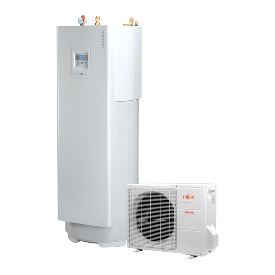
Loria duo 6000
Air/water heat pump
split, 2 services
Outdoor unit
WOYA 060 LFCA
WOYA 080 LFCA
WOYA 100 LFTA
Hydraulic unit
023010
023011
U0577305_1715_EN_10
11/04/2018
FR
NL
DE
EN
ES
PT
IT
PT
Installation manual
for professionals
to be kept by the user
for future reference
atlantic-comfort.com
PL
PT
Advertisement
Table of Contents

Subscribe to Our Youtube Channel
Related Manuals for Atlantic Loria duo 6000 Series


Summary of Contents for Atlantic Loria duo 6000 Series
- Page 1 Loria duo 6000 U0577305_1715_EN_10 11/04/2018 Air/water heat pump split, 2 services Outdoor unit Hydraulic unit WOYA 060 LFCA 023010 WOYA 080 LFCA 023011 WOYA 100 LFTA Installation manual for professionals to be kept by the user for future reference atlantic-comfort.com...
-
Page 2: Table Of Contents
Loria duo 6000 heat pump " This device must be installed by qualified personnel with a certificate of capacity for the handling of refrigerants Contents Description of the equipment Packaging Description Definitions Operating principle Specifications Layout Installation and maintenance rules Installing the outdoor unit Unpacking and reservations Installing the hydraulic unit... - Page 3 Loria duo 6000 heat pump Controller User interface Start temperature calculation Room thermostat (optional) Regulation parameters Information and troubleshooting Displaying information Outdoor unit errors Hydraulic unit errors Safety thermostat Maintaining the installation Accessing the components of the appliance Checking the outdoor unit Hydraulic checks Electrical checks Maintenance of the domestic hot water tank...
-
Page 4: Description Of The Equipment
Loria duo 6000 heat pump Packing list Heat pump Outdoor unit Hydraulic unit Model Code (export) Model Ref. Model Ref. Loria duo 6004 522963 Loria duo 6004 023010 WOYA060LFCA 700171 Loria duo 6006 522964 Loria duo Loria duo 6008 522965 WOYA080LFCA 700172 023011... - Page 5 Loria duo 6000 heat pump Model name Loria duo 6004 6006 6008 6010 Power absorbed +7 °C/+35°C - floor heating system 0 82 1 28 1 77 2 37 -7 °C/+35°C - floor heating system 1 42 1 77 2 33 3 11 +7 °C/+45°C - LT radiators 1 13...
- Page 6 Loria duo 6000 heat pump " Hydraulic unit 1768 1750 1777 1711 Front view Side view 80 84 ø Heating outgoing flow (area 1) M 26x34 ø Heating return flow (area 1) M 26x34 ø Heating outgoing flow (optional area 2) D1 D2 26x34 ECS L...
- Page 7 Loria duo 6000 heat pump " Outdoor unit, Loria duo 6004, 6006 and 6008 models 4 holes Ø11 4 holes Ø11 " Outdoor unit, Loria 6010 model figure 2 - Dimensions of the outdoor unit in mm - 7 - Installation manual "1715 - EN"...
- Page 8 Loria duo 6000 heat pump max. speed figure 4 - Hydraulic pressures and flow rates available B3977 35000 30000 25000 20000 10 k , 25 °C 15000 10000 5000 °C 90 100 HP return sensor. HP outgoing sensor. Outdoor sensor QAC2030 NTC. figure 5 - Ohmic value of the sensors (hydraulic unit - Outdoor sensor) 10000...
-
Page 9: Description
Loria duo 6000 heat pump Description " Loria duo 6008 model " Loria duo 6004 and 6006 models Key: Electronic expansion valve of the main circuit. High performance propeller and low noise level. "Inverter" compressor acoustically and thermally Electrical motor with variable "Inverter" operation. insulated. - Page 10 Loria duo 6000 heat pump Front view Side view Key: Electric box. Controller / User interface 10 "Gas" refrigeration connection. 21 Flow meter. (description, see § 7.1, page 11 "Liquid" refrigeration connection. 22 DHW electrical backup 40). 12 Safety valve. 23 Anode Hydraulic system (circulation 13 Automatic air bleeder.
- Page 11 Loria duo 6000 heat pump - 11 - Installation manual "1715 - EN"...
-
Page 12: Operating Principle
Loria duo 6000 heat pump Operating principle • Regulation functions - The initial temperature of the heating circuit is The heat pump transmits the energy contained in the controlled by the weather-dependent setpoint. surrounding air into the residence to be heated. - The power of the outdoor unit is modulated according The heat pump consists of four main elements, in which to the need via the "inverter"... - Page 13 Loria duo 6000 heat pump • Domestic hot water (DHW) operating principle Two domestic hot water (DHW) temperatures can be To ensure that the DHW setpoint is reached, the set: electrical back-up system must be left on. - Comfort temperature ( ) and production takes...
-
Page 14: Layout
Loria duo 6000 heat pump 2 Layout Installation and maintenance rules Unpacking and reservations The appliance must be installed and maintained by an 2 2 1 Acceptance approved professional in accordance with the prevailing In the presence of the carrier, carefully inspect the regulations and code of practice, in particular: general appearance of the appliances and check that Belgium:... -
Page 15: Positioning The Refrigerant Connections
Loria duo 6000 heat pump 2 2 4 Accessories provided to monitor the outdoor Outdoor sensor temperature. Adapter 1/2" - 5/8" (*) and/or to connect the flared 1/4" - 3/8" connection of the hydraulic unit. Nut 1/2" and/or 1/4" models 6004 - 6006 only (see table figure 18, page 21). -
Page 16: Installing The Outdoor Unit
Loria duo 6000 heat pump Installing the outdoor unit may drop below 0°C for a long period of time, check that the ice does not cause any danger. A drainage 2 4 1 Installation precautions pipe can also be connected to the outdoor unit (see page 17). - Page 17 Loria duo 6000 heat pump 2 4 2 Positioning the outdoor unit The outdoor unit must be raised by at least 50 mm from the ground. In snowy regions, this height must be increased but must not exceed 1.5 m (figure 13).
-
Page 18: Installing The Hydraulic Unit
Loria duo 6000 heat pump Installing the hydraulic unit 2 5 1 Installation precautions 300 mm • Choose the installation site after talks with the mini customer. • The room where the appliance operates must comply with the regulations in force. •... -
Page 19: Refrigerant Connection And Filling The Installation With Gas
Loria duo 6000 heat pump 3 Refrigerant connection and filling the installation with gas " This appliance uses refrigerant R410A insulating sleeves with a thermal conductivity equal to 0.045 W/mK or less when the temperature is 20°C. Comply with the legislation for handling refrigerants. The insulation must be impermeable to prevent steam from passing during the defrosting cycles (glass wool Rules and precautions... -
Page 20: Checks And Connections
Loria duo 6000 heat pump Checks and connections Liaison Gas link " The refrigeration circuit is very sensitive Azote to dust and humidity: check that the area Nitrogen around the connection is clean and dry before removing the caps protecting the refrigeration connectors "... - Page 21 Loria duo 6000 heat pump Heat pump model Loria duo 6004, 6006 Loria duo 6008 Loria duo 6010 liquid liquid liquid Outdoor unit connections 1/2" 1/4" 5/8" 1/4" 5/8" 3/8" Diameter (D1) 1/2" (D2) 1/4" (D1) 5/8" (D2) 1/4" (D1) 5/8" (D2) 3/8"...
-
Page 22: Filling The Installation With Gas
Loria duo 6000 heat pump Filling the installation with gas " This operation is only to be carried out by qualified fitters in compliance with the legislation for the handling of refrigerants " Creating a vacuum with a vacuum pump is essential (see ANNEX 1). "... - Page 23 Loria duo 6000 heat pump 3 4 1 Leak test Refrigerant connexion - Remove the protective plugs (B) from the charging (gas) hole (Schrader) in the gas valve (large diameter). - Connect the high pressure hose from the Manifold to Plug (A) 3-way valve the load orifice...
- Page 24 Loria duo 6000 heat pump 3 4 2 Pump down 3 4 3 Filling the installation with gas The 3-vacuum method (ANNEX 2) is highly If an additional charge is required, add the recommended for all installations, especially additional charge before filling the hydraulic unit when the outdoor temperature is below 10°C.
-
Page 25: Additional Charge
Loria duo 6000 heat pump Collecting refrigerant Additional charge in the outdoor unit Loria duo ... 25 g of R410A Loria duo ... 25 g of R410A " Ensure that all electrical power supplies have 6004, 6006 and 6008 per extra metre 6004, 6006 and 6008 per extra metre been cut off before starting work. -
Page 26: Hydraulic Connections
Loria duo 6000 heat pump 4 Hydraulic connections Overview " The connection must comply with good engineering practices according to the regulations in force. Reminder: Make the assembly seals according to good engineering practices in force for plumbing work: - Use suitable seals (fibre seals, O rings). - Use Teflon or hemp tape. -
Page 27: Connecting To An Underfloor Heating Circuit
Loria duo 6000 heat pump " Bypass or Open Loop mandatory for each area (A) Bypass (a) Area controlled by thermostat on valve and room thermostat. (a) Area controlled by thermostat on valve and remote control. (B) Open loop (c) Area controlled by the HP. figure 24 - Connecting the floor heating system Connecting to an Connecting to the DHW circuit... -
Page 28: Overall Hydraulic Layout
Loria duo 6000 heat pump Overall hydraulic layout Installation configuration - see page 55 4 - 1 - Pre-setting (1 heating circuit) Parameter - 28 - Installation manual "1715 - EN"... - Page 29 Loria duo 6000 heat pump Installation configuration - see page 44 Parameter 4 - 2 (2 heating circuits) - 29 - Installation manual "1715 - EN"...
-
Page 30: Electrical Connections
Loria duo 6000 heat pump 5 Electrical connections Electrical power connections (LV) • Connecting to screw terminals " Use of ring terminals or tips is prohibited Always check that the electric power supply is switched off before works. - Always choose a rigid wire that complies with current standards. - Page 31 Loria duo 6000 heat pump 5 1 3 Overview of the electrical connections The electrical diagram of the hydraulic unit is detailed in page 60 Outdoor sensor cable 2 x 0.5 mm² Room thermostat (optional) °C cable 2 x 0.5 mm² Interconnection between outdoor unit and hydraulic unit: Phase, Neutral, Earth, Communication bus...
- Page 32 Loria duo 6000 heat pump 5 1 5 Electrical connections on the outdoor unit side - Make the connections according to the diagram To access the connector terminals: (figure 27). - Use cable clamps to prevent the conductors from • Loria duo 6004, 6006 and 6008 models being disconnected accidentally.
- Page 33 Loria duo 6000 heat pump 5 1 6 Electrical connections on the hydraulic unit side To access the connector terminals: - Remove the front panel (2 screws Ø 13). - Rotate the electric box (2 screws - figure 30, page SELV cable LV cable bushing bushing (sensors)
- Page 34 Loria duo 6000 heat pump - Do not place the sensor lines and the sector supply Ensure that all of the electrical cables are housed in the lines in parallel in order to avoid interferences due to spaces provided (figure 32).
- Page 35 Loria duo 6000 heat pump • Interconnection between the outdoor unit and the • Energy meter hydraulic unit A signal is used to show the energy distribution for Comply with the correspondence between the markings Heating/DHW functions by connecting a compatible on the hydraulic unit's terminals and those on the energy meter.
-
Page 36: Electrical Connections - Selv
Loria duo 6000 heat pump Electrical connections - SELV The elements described below are Safety Extra-Low Comply with the safety distances between SELV and LV Voltage devices (SELV). Comply with the regulations (power) cables. applicable to such devices. Ensure that all of the electrical cables are housed in the spaces provided (figure 34). - Page 37 Loria duo 6000 heat pump 5 2 2 Room thermostat " Dynamic radiator or fan-coil area If the installation is equipped with fan-coils / dynamic radiators, do not use a room thermostat " Radiator or floor heating area 1 . 2 m Consult the assembly instructions on the packaging of the sensor.
-
Page 38: Commissioning
Loria duo 6000 heat pump 6 Commissioning Checks before commissioning 6 2 3 Draining the hydraulic unit Press and hold the button for 5 seconds; the • Hydraulic circuit display will show the “ ” icon. - Make sure that the installation has been rinsed. (Appliance test) to 10 (automatic - Set parameter - Check the water flow direction and that all of the valves... -
Page 39: Cleaning The Sediment Trap
Loria duo 6000 heat pump Cleaning the sediment trap Immediately after commissioning, clean the filter of the sediment trap (remove waste generated by the installation: seals, oakum, filings, etc.). - Remove the filter protection sheath to easily remove Before works, check that the working environment is ferrous particles. -
Page 40: Controller
Loria duo 6000 heat pump 7 Controller User interface Ref. Functions - Definition of the functions • SELECT - Browse and select the available uses • MODE - Browse and select the mode for the pre-selected use. • Settings keys - Configure the setpoints of the selected function using the •... -
Page 41: Room Thermostat (Optional)
Loria duo 6000 heat pump Room thermostat (optional) • Description of the display (user interface). Screen Settings buttons °C Icons Definitions Adjustment Access the User settings Programming knob button (manual mode) Use for heating Select mode "Boost" (reference to the circuit concerned Z1 or Z2) (automatic, manual, holiday, button stand-by: the use concerned is Off) -
Page 42: Start Temperature Calculation
Loria duo 6000 heat pump Start temperature calculation The weather-dependent setpoint offset (parameter 31/51) modifies the initial temperature of all the curves, 7.3.1 Weather-dependent control without modifying the slope (figure 39). The operation of the heat pump is controlled by the The corrective actions if discomfort is experienced are weather-dependent setpoint. -
Page 43: Regulation Parameters
Loria duo 6000 heat pump Feelings... Corrective actions on the weather-dependent setpoint: ... in cold weather Slope (line 30 / 50) Offset (line 31 /51) ... in warm weather & No correction No correction Cold & Cold & & No correction Cold Cold &... - Page 44 Loria duo 6000 heat pump 7.4.4 List of parameters Description of parameter Configurationor display range Basic setting Time / Date setting Hours / minutes 00:00 23:59 01:00 MM-DD Month / Day 1 - 1 ..12 - 31 YYYY Year 2018 Installation configuration Two heating circuits option...
- Page 45 Loria duo 6000 heat pump Description of parameter Configurationor display range Basic setting phase of the selected day (end of comfort) 00:15 24:00 - -:- - phase of the selected day (start of comfort) 00:00 23:45 - -:- - phase of the selected day (end of comfort) 00:15 24:00 - -:- -...
- Page 46 Loria duo 6000 heat pump Description of parameter Configurationor display range Basic setting Cooling setting , circuit 1 (direct) Cooling authorisation (circuit 1) 0 (not allowed)... 1 (allowed)... Cooling curve slope 0 10 4 00 Cooling curve displacement -4.5... 4.5°C 0 °C Min.
- Page 47 Loria duo 6000 heat pump Description of parameter Configurationor display range Basic setting Correction of outdoor temperature sensor - 5... 5 °C 1 (appliance locked) Behaviour of the appliance when suffering from 2 (Area 1 off) an external error - EX3 (see table page 50).
-
Page 48: Information And Troubleshooting
Loria duo 6000 heat pump 8 Information and troubleshooting Displaying information button calls up various information. Depending on the appliance type, the configuration and the state of operation, certain information lines may not be available. " Status list " List of information Value... -
Page 49: Hydraulic Unit Errors
Loria duo 6000 heat pump Hydraulic unit errors The faults or breakdowns of the hydraulic unit are reported on the display unit of the user interface. The display shows the "Erxxx" error code. A minor error does not result in switching the appliance to safety mode. A major error results in switching the appliance to safety mode. - Page 50 Loria duo 6000 heat pump " Visible faults on the digital display Error codes Description Switched to safety mode Probable causes Minor Major error error Too much draw-off during the same Appliance shutdown if cycle. DHW cycle too long (> 6 hours). the error 67 occurs 3 DHW back-up disconnected.
-
Page 51: Outdoor Unit Errors
Loria duo 6000 heat pump Outdoor unit errors In the event of an error occurring within the outdoor unit, the user interface displays the "Er 66" error code. View the information menu : Information " No. 18" specifies the error code for the outdoor unit " xx"... -
Page 52: Maintaining The Installation
Loria duo 6000 heat pump 9 Maintaining the installation Hydraulic checks " Ensure that all electrical power supplies have been cut off before starting work. Regular maintenance is required to protect the HP. Note: Protection via the detection of the minimum flow Stored energy: after disconnecting the "... -
Page 53: Maintenance Of The Domestic Hot Water Tank
Loria duo 6000 heat pump Maintenance of the Electrical checks domestic hot water tank - Check connections and tighten where necessary. The tank must be serviced once a year (the frequency - Check the condition of the cabling and plates. may vary according to the hardness of the water). -
Page 54: Accessing The Electric Box
Loria duo 6000 heat pump 10 Maintenance " Ensure that all electrical power supplies have been cut off before starting work. Stored energy: after disconnecting the power supplies, wait 1 minute before accessing the internal " parts of the equipment (180°) - A - Unscrew the 3 screws. - Page 55 Loria duo 6000 heat pump - 55 - Installation manual "1715 - EN"...
-
Page 56: Electrical Wiring (Outdoor Unit)
Loria duo 6000 heat pump 11 Electrical wiring diagrams 11 1 Electrical wiring (outdoor unit) Electrical connections on the outdoor unit: § 5.1.5, page 32. Réactance Réactance Compresseur Sonde température Sonde température CN73 2 CN72 Détendeur électronique Compresseur Sonde température Evaporateur Capteur CN39... - Page 57 Loria duo 6000 heat pump Pressure sensor CN90 Compressor Regulation board CN64 Temperature sensors (Main PWB) Expansion valve Temperature sensors CN72 CN42 CN40 CN200 CN400 Outdoor 1 2 3 4 5 1 2 3 4 5 6 7 8 9 1 2 3 4 CN62 1 2 3 4 5...
- Page 58 Loria duo 6000 heat pump Sonde température Détendeur électronique CN72 Capteur de pression CN90 Carte de régulation Sonde température Compresseur CN64 Sonde température Extérieur CN42 CN40 CN200 CN400 CN62 1 2 3 4 1 2 3 4 Sonde température Evaporateur CN65 Sonde température Refoulement...
- Page 59 Loria duo 6000 heat pump - 59 - Installation manual "1715 - EN"...
- Page 60 Loria duo 6000 heat pump 11 2 Electrical wiring (hydraulic unit - excluding connections made by the installer) Electrical connections on the hydraulic unit: see § 5.1.6, page 33 2ème circuit 2nd circuit 1 2 3 CN18 CN21 CN30 ...
- Page 61 Loria duo 6000 heat pump Colour codes Thermostat appoint chauffage Heating back-up thermostat BK Black BN Brown BU Blue GN Green GY Grey OG Orange RD Red VT Violet WH White YE Yellow Relais appoint sanitaire Hot water back-up relay ...
-
Page 62: Commissioning Check-List
Loria duo 6000 heat pump 12 Quick-start procedure Before switching on the hydraulic unit : • Check the electrical cabling. • Check that the refrigeration circuit is filled with gas. • Check the hydraulic circuit's pressure (1 to 2 bars), check that the heat pump is drained, along with the rest of the installation. - Page 63 Loria duo 6000 heat pump 12 1 2 Start-up • Quick start-up (see section "6.2 Commissioning", page Non-compliant & § "List of parameters", page 44) Push in the installation's circuit breakers (outdoor unit power supply) 2 hours before the tests => Compressor preheating. Operation of the circulation pump.
-
Page 64: Settings Sheet
Loria duo 6000 heat pump 12 2 Settings sheet Parameter Name Settings Parameter Name Settings Domestic hot water Preliminary settings Legionella cycle hour / minutes Month - Day DHW forced operation (boost) 25 => 29 time programmes Year Energy counting Two heating circuits option EU reference power (see general cooling authorisation... -
Page 65: Start-Up Data Sheet
Loria duo 6000 heat pump 12 3 Start-up data sheet Worksite Installer Serial No. Serial No. Outdoor unit Hydraulic unit Model Model Type of refrigerant Refrigerant charge Checks Voltages and currents in operation on the outdoor unit Compliance with positioning distances Correct condensate discharge Electric connections / connections tightened No GAS leaks... -
Page 66: Erp Definition
- According to the labelling directive, energetic efficiency shall be displayed to encourage end users to purchase energy-efficient products. 14 2 ERP Specifications Trade name / Product name: atlantic / ... Loria duo 6004 Loria duo 6006 Loria duo 6008... - Page 67 Loria duo 6000 heat pump Trade name / Product name: atlantic / ... Loria duo 6004 Loria duo 6006 Loria duo 6008 Loria duo 6010 Reference 522 963 522 964 522 965 522 966 Heating ranges 35°C 55°C 35°C 55°C 35°C...
-
Page 68: Package Sheet
Loria duo 6000 heat pump 14 3 Package sheet Modulating room thermostat references 076310 (Room thermostat UA55) (outdoor sensor included in the package) Outdoor sensor included in the combined package Controller class Controller class Contribution to seasonal efficiency Contribution to seasonal efficiency "... - Page 69 Loria duo 6000 heat pump - 69 - Installation manual "1715 - EN"...
- Page 70 Please contact your installer or local representative for more information. * Depending on the national regulations of each member state. Date of commissioning: atlantic-comfort.com Société Industrielle de Chauffage SATC - BP 64 - 59660 MERVILLE - FRANCE Address of your heating installer or customer service.
Need help?
Do you have a question about the Loria duo 6000 Series and is the answer not in the manual?
Questions and answers