
Related Manuals for Texas Instruments AWR1443


Summary of Contents for Texas Instruments AWR1443
- Page 1 AWR1443, AWR1243 Evaluation Module (AWR1443BOOST, AWR1243BOOST) mmWave Sensing Solution User's Guide Literature Number: SWRU507A May 2017 – Revised May 2017...
-
Page 2: Table Of Contents
PC Connection ........................Antenna ..................Jumpers, Switches, and LEDs ..................Design Files and Software Tools ..........Software, Development Tools, and Example Codes for AWR1443 ....................Mechanical Mounting of PCB ..............PCB Storage and Handling Recommendations ....................... Regulatory Information .......................... Revision History Table of Contents SWRU507A –... - Page 3 20-Pin Connector Definition (J5) ..................20-Pin Connector Definition (J6) ....................HD Connector Pin Definition ......................... SOP Modes ........................ Push Buttons ......................... LEDs SWRU507A – May 2017 – Revised May 2017 List of Figures Submit Documentation Feedback Copyright © 2017, Texas Instruments Incorporated...
-
Page 4: Trademarks
SWRU507A – May 2017 – Revised May 2017 AWR1443BOOST, AWR1243BOOST Evaluation Module mmWave Sensing Solution Trademarks BoosterPack, LaunchPad are trademarks of Texas Instruments. ARM is a registered trademark of ARM Limited. Windows is a registered trademark of Microsoft Corporation. AWR1443BOOST, AWR1243BOOST Evaluation Module mmWave Sensing SWRU507A –... -
Page 5: Getting Started
< 3 m. 2.3.2 mmWave Proximity Demo TI provides sample demo codes to easily get started with the AWR1443 evaluation module and experience the functionality of the AWR1443 mmWave sensor. For details on getting started with these demos, see the mmWave SDK User Guide. -
Page 6: Hardware
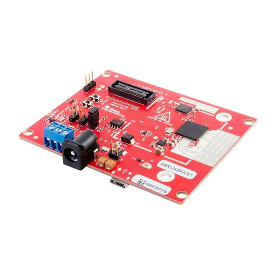
Onboard Antenna AWR1443 Flash 60-Pin HD Connector Figure 1. EVM Front View AWR1443BOOST, AWR1243BOOST Evaluation Module mmWave Sensing SWRU507A – May 2017 – Revised May 2017 Solution Submit Documentation Feedback Copyright © 2017, Texas Instruments Incorporated... -
Page 7: Evm Rear View
Connector PMIC 20-Pin LaunchPad Connector (J5) 20-Pin LaunchPad Connector (J6) XDS110 Figure 2. EVM Rear View SWRU507A – May 2017 – Revised May 2017 AWR1443BOOST, AWR1243BOOST Evaluation Module mmWave Sensing Solution Submit Documentation Feedback Copyright © 2017, Texas Instruments Incorporated... -
Page 8: Block Diagram
20-pin connectors. The connectors do not have a key to prevent the misalignment of the pins or reverse connection. Therefore, ensure reverse mounting does not take place. On the AWR1443 BoosterPack, we have provided 3V3 marking near pin 1 (see Figure 4). -
Page 9: Power Connections
LaunchPads, ensure the pin 1 orientation is correct by matching the 3V3 and 5-V signal marking on the boards (see Figure Figure 6. 20-Pin BoosterPack™ Connectors (J5 and J6) SWRU507A – May 2017 – Revised May 2017 AWR1443BOOST, AWR1243BOOST Evaluation Module mmWave Sensing Solution Submit Documentation Feedback Copyright © 2017, Texas Instruments Incorporated... - Page 10 Enable signal is released. NOTE: To enable this feature, the R102 resister must be populated on the EVM. • ANA1/2/3/4 – These are inputs to the GPADCs (general purpose ADC) available on the AWR1443 device. AWR1443BOOST, AWR1243BOOST Evaluation Module mmWave Sensing SWRU507A –...
-
Page 11: High Density Connector (60 Pin)
HOSTINT SPI_MOSI SPI_MISO PGOOD (onboard VIO) NERROUT SYNC_IN DEBUG_VALIDP DEBUG_VALIDM DEBUG_FRCLKP DEBUG_FRCLKM DEBUG/CSI_3P DEBUG/CSI_3M DEBUG/CSI_2P DEBUG/CSI_2M SWRU507A – May 2017 – Revised May 2017 AWR1443BOOST, AWR1243BOOST Evaluation Module mmWave Sensing Solution Submit Documentation Feedback Copyright © 2017, Texas Instruments Incorporated... -
Page 12: Can Connector
MCU must ensure that it does not drive any I/O signals to the AWR device before this I/O supply is stable, to avoid leakage current into the I/Os. 3.4.3 CAN Interface Connector (for AWR1443) The J3 connector provides the CAN_L and CAN_H signals (see Figure 8) from the onboard CAN transceiver (SN65HVDA540). -
Page 13: Pc Connection
Details on this board can be found at http://www.ti.com/tool/tsw1400evm For details on these use cases, see the mmWave-DevPack User Guide. SWRU507A – May 2017 – Revised May 2017 AWR1443BOOST, AWR1243BOOST Evaluation Module mmWave Sensing Solution Submit Documentation Feedback Copyright © 2017, Texas Instruments Incorporated... -
Page 14: Antenna
(H-plane) and elevation plan (E-plane) is as shown in Figure 11 Figure Figure 11. Antenna Pattern in H-Plane AWR1443BOOST, AWR1243BOOST Evaluation Module mmWave Sensing SWRU507A – May 2017 – Revised May 2017 Solution Submit Documentation Feedback Copyright © 2017, Texas Instruments Incorporated... -
Page 15: Antenna Pattern In E-Plane
Hardware www.ti.com Figure 12. Antenna Pattern in E-Plane SWRU507A – May 2017 – Revised May 2017 AWR1443BOOST, AWR1243BOOST Evaluation Module mmWave Sensing Solution Submit Documentation Feedback Copyright © 2017, Texas Instruments Incorporated... -
Page 16: Jumpers, Switches, And Leds
Jumpers, Switches, and LEDs 3.7.1 Sense On Power Jumpers The AWR1443 and AWR1243 devices can be set to operate in three different modes, based on the state of the SOP (sense on power) lines (see Figure 13). These lines are only sensed during boot up of the AWR device. -
Page 17: Push Buttons
AWR device. This LED turns on when the Yellow GPIO_1 GPIO is logic-1. SWRU507A – May 2017 – Revised May 2017 AWR1443BOOST, AWR1243BOOST Evaluation Module mmWave Sensing Solution Submit Documentation Feedback Copyright © 2017, Texas Instruments Incorporated... -
Page 18: Design Files And Software Tools
Mechanical Mounting of PCB The field of view of the radar sensor is orthogonal to the PCB. The L-brackets provided with the AWR1443 and AWR1243 EVM kit, along with the screws and nuts help in the vertical mounting of the EVM. -
Page 19: Pcb Storage And Handling Recommendations
All ESD precautions must be taken while using and handling the EVM. Regulatory Information The AWR1443 and AWR1243 evaluation modules (AWR1443BOOST and AWR1243BOOST) are in compliance with Directive 2014/53/EU. The full text of TI's EU Declaration of Conformity is available here. -
Page 20: Revision History
Changed mmWave SDK UG link..........• Changed Antenna Pattern in H-Plane and Antenna Pattern in E-Plane images ....................• Added Regulatory Conformity section. Revision History SWRU507A – May 2017 – Revised May 2017 Submit Documentation Feedback Copyright © 2017, Texas Instruments Incorporated... - Page 21 IMPORTANT NOTICE FOR TI DESIGN INFORMATION AND RESOURCES Texas Instruments Incorporated (‘TI”) technical, application or other design advice, services or information, including, but not limited to, reference designs and materials relating to evaluation modules, (collectively, “TI Resources”) are intended to assist designers who are developing applications that incorporate TI products;...
- Page 22 Mouser Electronics Authorized Distributor Click to View Pricing, Inventory, Delivery & Lifecycle Information: Texas Instruments AWR1443BOOST AWR1243BOOST...
Need help?
Do you have a question about the AWR1443 and is the answer not in the manual?
Questions and answers