Table of Contents
Advertisement
Available languages
Available languages
Quick Links
Advertisement
Table of Contents

Related Manuals for Outsunny 842-005V60


Summary of Contents for Outsunny 842-005V60
- Page 1 INbza022V01_FR 842-005V60 PARASOL CHAUFFANT PATIO HEATER IMPORTANT - CONSERVEZ CES INFORMATIONS POUR VOTRE CONSULTATION ULTÉRIEURE: LISEZ ATTENTIVEMENT IMPORTANT, RETAIN FOR FUTURE REFERENCE: READ CAREFULLY...
-
Page 2: Consignes De Sécurité
CONSIGNES DE SÉCURITÉ VEUILLEZ LIRE LES INSTRUCTIONS SUIVANTES AVANT D'UTILISER CE CHAUFFAGE. POUR VOTRE SÉCURITÉ Si vous sentez une odeur de gaz : 1. Fermez la vanne de gaz de l'appareil. 2. Éteignez toute flamme nue. 3. Si l'odeur persiste, appelez votre fournisseur de gaz ou un service d'urgence. - Page 3 AVERTISSEMENT Prenez connaissance des instructions avant installation et utilisation. -Cet appareil doit être installé et la bonbonne de gaz conservée conformément à la réglementation. -Ne pas obstruer les orifices de ventilation de la bonbonne. -Ne pas déplacer l'appareil lorsqu'il est en marche. -Fermer la vanne de la bonbonne de gaz ou du détendeur avant de déplacer l'appareil.
- Page 4 ATTENTION LISEZ ATTENTIVEMENT LES DIRECTIVES SUIVANTES AVANT TOUTE UTILISATION ● Ne pas utiliser ce chauffage à l'intérieur ; cela pourrait causer des blessures ou des dommages matériels. ● Ne pas installer cet appareil sur des véhicules de loisirs et/ou des bateaux. ●...
- Page 5 ● Vérifier immédiatement le chauffage si l'une des situations suivantes se produit : -Le chauffage n'atteint pas la température requise. -Le brûleur émet un bruit sec pendant l'utilisation (un léger bruit est normal lorsque le brûleur est éteint). -Une odeur de gaz et un jaunissement extrême des flammes. ●...
-
Page 6: Test De Fuite
SUPPORT ET EMPLACEMENT DU CHAUFFAGE PLAFOND • Ce chauffage ne doit être utilisé qu'à l'extérieur. • Les matériaux combustibles doivent être à une distance d'au moins 100 cm du haut et des côtés de ce chauffage. • Le chauffage doit être placé sur un sol plat et ferme. •... - Page 7 VISSERIE Article Description Qté Écrou à bride M8 (emballé avec la partie I) Boulon M8x16 (2pcs emballés avec la partie I) Écrou à bride M6 Boulon en acier inoxydable (pré-assemblé sur la partie C) Boulon M6x30 Entretoise de réflecteur Rondelles Boulon de poteau (pré-assemblé...
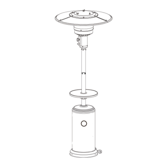
- Page 8 PIÈCES Article Description Qté Panneau réflecteur Réflecteur central Ensemble brûleur Boîtier du réservoir Poteau supérieur Poteau inférieur Support Base Ensemble roue Détendeur (en option) Coupleur à vis Table Entretoise de serrage Écrou de fixation...
-
Page 9: Spécifications
A. Construction et caractéristiques •Chauffage de terrasse/jardin transportable avec boîtier de bonbonne. •Boîtier en acier avec revêtement en poudre ou en acier inoxydable. •Émission de chaleur par le réflecteur B. Spécifications •Utiliser uniquement du gaz propane, butane ou leurs mélanges. •Puissance maximale : 13000 watts. -
Page 10: Instructions D'assemblage
INSTRUCTIONS D'ASSEMBLAGE Étape 1 Retournez la base, puis fixez la roue (I) à la base (H) à l'aide de deux écrous à bride M8 (AA) et de deux bou- lons M8X16 (BB). Fixez trois bras d'ancrage (MM) à la base (H) à l'aide de six écrous M6 (OO) et de six bou- lons M6X10 (NN). - Page 11 INSTRUCTIONS D'ASSEMBLAGE Étape 4 Placez le boîtier de la bonbonne sur le poteau, puis faites glisser le boîtier du réservoir vers le bas. Facultatif : Installation de la table Faites glisser l'écrou de fixation (N) le long du poteau (F) avec le côté arrondi vers le bas. Puis, faites glisser l'entretoise de serrage (M) le long du poteau (F), le côté...
- Page 12 INSTRUCTIONS D'ASSEMBLAGE Étape 6 Retirez les quatre boulons (HH) du montant inférieur (F). Insérez le tuyau à gaz à l'extrémité supérieure du poteau inférieur (F). Raccordez le poteau supérieur (E) au poteau inférieur (F). Serrez les deux montants à l'aide des quatre boulons (HH), qui ont été...
- Page 13 INSTRUCTIONS D'ASSEMBLAGE Étape 8 Fixez trois entretoises de réflecteur (FF) et trois rondelles (GG) sur le brûleur (C). Serrez les entre- toises du réflecteur. Faites glisser trois rondelles (GG) sur l'extrémité filetée de l'entretoise. Fixez l'ensemble du réflecteur au sommet de l'entre- toise (FF) à...
-
Page 14: Contrôle Des Fuites
CONTRÔLE DES FUITES AVERTISSEMENT! Un contrôle d'étanchéité doit être effectué chaque année, chaque fois qu'une bouteille est branchée ou si des pièces du système de gaz sont remplacées. AVERTISSEMENT! N'utilisez jamais de flamme nue pour détecter les fuites de gaz. Assurez-vous qu'il n'y a pas d'étincelles ou de flammes nues lors de la vérification des fuites. - Page 15 FONCTIONNEMENT Avant d'effectuer un test d'étanchéité, assurez-vous que la zone est exempte d'étincelles et que vous vous trouvez dans une zone extérieure spacieuse. Raccordez la bouteille de gaz propane au régulateur - assurez-vous que le robinet de l'appareil est fermé. Badi- geonnez la solution d'eau et de savon sur toutes les connexions.
-
Page 16: Dépannage
DÉPANNAGE Problème Cause Solution Le brûleur ne s'allume pas. L'injecteur du brûleur est bouché. Nettoyez l'injecteur du brûleur. La pression d'alimentation en gaz est faible. Appelez votre fournisseur de gaz. flamme brûleur s'éteint La pression de gaz est faible. Appelez votre fournisseur de gaz. immédiatement après l'allumage. -
Page 17: Safety Instructions
SAFETY INSTRUCTIONS PLEASE READ THE FOLLOWING INSTRUCTIONS BEFORE USING THIS HEATER. If you smell gas: 1. Shut off the gas to the appliance. 2. Extinguish any open flame. 3. If the smell continues, call your gas supplier or emergency service. 1. - Page 18 WARNING - This appliance must be installed and the gas cylinder stored in accordance to the regulations. - Do not obstruct the ventilation holes of the cylinder. - Do not move the appliance when in operation. - Shut off the valve at the gas cylinder or regulator before moving the appliance.
- Page 19 CAUTION CAREFULLY READ THE FOLLOWING GUIDELINES BEFORE USE ● Do not use this heater indoors – it could cause personal injury or proper- ty damage. ● Do not install this appliance on recreational vehicles and/or boats. ● Installation and repair should be done by a qualified service person. ●...
- Page 20 ● Keep the LP regulator/hose assembly away from congested areas, so it cannot be tripped over. ● Ensure that any guard or protective device is on the heater when using. ● Keep away from the heater’s surface to avoid burns and damage to clothes.
- Page 21 ● This heater must only be used outdoors. ● Combustible materials should be at least 100cm away from the top and sides of this heater. ● Heaters must be place on a flat and firm ground. ● Never use this heater near petrol or other flammable liquids.
- Page 22 HARDWARE Item Description (packed with part I) M8 Flange Nut (2pcs packed with part I) Bolt M8x16 M6 Flange Nut (pre-assembled on part C) Stainless Steel Bolt Bolt M6x30 Reflector Spacer Washer (pre-assembled on part F) Post Bolt Screw M6x10 Cap Nut Wing Nut Wrench...
- Page 23 CONTENTS Item Description Reflector Panel Center Reflector Burner Assembly Tank Housing Upper Post Lower Post Support Bracket Base Wheel Assembly Regulator(optional) -23-...
- Page 24 The appliance requires approved hose in 1.4m length. -24-...
- Page 25 ASSEMBLY INSTRUCTIONS Step 1 Turn the base upside down, then attach the wheel (I) to the base (H) using two M8 flange nuts (AA) and two bolts M8X16 (BB). Attach three anchoring arms (MM) to the base (H) using six M6 nuts (OO) and six bolts M6X10 (NN).
- Page 26 ASSEMBLY INSTRUCTIONS Step 4 Load tank housing onto the post, then slide the tank housing down. Optional: Installing the table Slide fastening nut (N) down the post (F) with the rounded side facing down. Then, slide the tightening spacer (M) down the post (F) with the smaller side facing down.
- Page 27 ASSEMBLY INSTRUCTIONS Step 6 Remove the four bolts (HH) from the lower post (F). Insert the gas hose from the top end of the lower post (F). Connect the upper post (E) to the lower post (F). Tighten the two posts using the four bolts (HH),which were removed prior.
- Page 28 ASSEMBLY INSTRUCTIONS Step 8 Attach three reflector spacers (FF) and three washers (GG) to the burner (C). Tighten the reflector spacers. Slide three washers (GG) over the threaded end of the spacer. Attach the reflector assembly to the top of the spacer (FF) using three washers (GG) and three wing nuts (KK).
-
Page 29: Leak Check
LEAK CHECK WARNING! A leak test must be performed annually, each time a cylinder is hooked up or if parts of the gas system is replaced. WARNING! Never use an open flame to check for gas leaks. Ensure there are no sparks or open flames when checking for leaks. -
Page 30: Operation
OPERATION Before performing a leak test, ensure no sparks can occur and you are in a spacious outdoor area. Connect the propane gas tank to the regulator – ensure the valve on the unit is turned off. Brush the water and soap solution on all connections. Turn the gas supply on –... - Page 31 -31-...
Need help?
Do you have a question about the 842-005V60 and is the answer not in the manual?
Questions and answers