Table of Contents
Advertisement
Quick Links
Advertisement
Table of Contents

Subscribe to Our Youtube Channel
Related Manuals for Rohm BD82A26MUF-M


Summary of Contents for Rohm BD82A26MUF-M
- Page 1 BD82A26MUF-M Evaluation Board REFLED003-EVK-003...
-
Page 2: High Voltage Safety Precautions
[8] Be sure to wear insulated gloves when handling is required during operation. After Use [9] The ROHM Evaluation Board contains the circuits which store the high voltage. Since it stores the charges even after the connected power circuits are cut, please discharge the electricity after using it, and please deal with it after confirming such electric discharge. - Page 3 Boost DC/DC Converter for Automotive BD82A26MUF-M Evaluation Board REFLED003-EVK-003 Introduction This user’s guide will provide the necessary steps to operate the Evaluation Board of ROHM’s BD82A26MUF-M LED Driver. This document includes the external parts, operating procedures and application data. Description This Evaluation Board was developed for ROHM’s LED Driver BD82A26MUF-M.
-
Page 4: Evaluation Board Setup
Connect pulse generator to PWM-pin. It should be 100Hz to 25kHz and the minimum pulse width must be longer than 0.5μs. Turn on the power supply for +B-pin. Turn on the power supply for EN-pin. Turn on the pulse generator for PWM-pin. © 2023 ROHM Co., Ltd. 66UG041E Rev.001 Sep.2023... -
Page 5: Operation Mode Settings
REG50 with 100kΩ and pull down to GND with 20kΩ. 100 kΩ LED6 LED5 20 kΩ LED4 LED3 LED2 LED1 Figure 4. Setting LED6 to Unused Pin configuration Figure 5. Pin configuration © 2023 ROHM Co., Ltd. 66UG041E Rev.001 Sep.2023... -
Page 6: Evaluation Board Schematic
User’s Guide REFLED003-EVK-003 Evaluation board schematic Figure 6. Evaluation board schemati Figure 6. Evaluation board schematic © 2023 ROHM Co., Ltd. 66UG041E Rev.001 Sep.2023... -
Page 7: Parts List
100kΩ, 1/16W MCR01 series Resistor ROHM RPLS2 1005 100kΩ, 1/16W MCR01 series Resistor ROHM 1005 200Ω, 1/16W MCR01 series Resistor ROHM CPC1 1608 1μF, X7R, 16V GCM188R71C105KA49 Ceramic Murata CPC2 1005 Open Ceramic © 2023 ROHM Co., Ltd. 66UG041E Rev.001 Sep.2023... - Page 8 RLED2 1005 Open Resistor RLED3 1005 Open Resistor RLED4 1005 Open Resistor RLED5 1005 Open Resistor RLED6 1005 Open Resistor 1005 Short 1005 Short 1005 Short 1005 Short 1005 Short 1005 Short © 2023 ROHM Co., Ltd. 66UG041E Rev.001 Sep.2023...
-
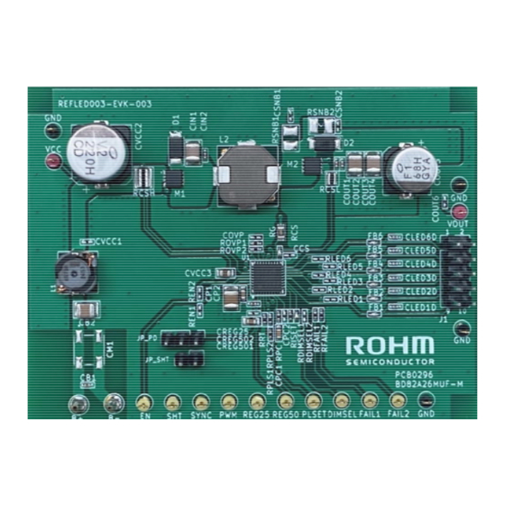
Page 9: Board Layout
The layout of REFLED003-EVK-003 is shown below. Figure 7. Top layer layout Figure 8. 2nd layer layout (Top view) (Top view) (Top view) Figure 10. Bottom layer layout Figure 9. 3rd layer layout (Top view) (Top view) © 2023 ROHM Co., Ltd. 66UG041E Rev.001 Sep.2023... -
Page 10: Reference Application Data
Reference application data (Ta=25°C, Output voltage=25.3V, Iout=125mA x 6ch) Input voltage (V) Figure 11. Efficiency vs Input voltage Phase Gail -120 -180 1000 10000 100000 1000000 Frequency(Hz) Figure 12. Gain, Phase vs Frequency (VCC=13.5V) © 2023 ROHM Co., Ltd. 66UG041E Rev.001 Sep.2023... -
Page 11: Revision History
User’s Guide REFLED003-EVK-003 Revision history Revision Date Description number 1. Sep. 2023 Initial release © 2023 ROHM Co., Ltd. 66UG041E Rev.001 Sep.2023... - Page 12 Specific Applications). Unless otherwise agreed in writing by ROHM in advance, ROHM shall not be in any way responsible or liable for any damages, expenses, or losses incurred by you or third parties arising from the use of ROHM Products for Specific Applications.
Need help?
Do you have a question about the BD82A26MUF-M and is the answer not in the manual?
Questions and answers