Advertisement
Quick Links
Primary Buck DC/DC Converter Series
Single 440 kHz Buck DC/DC Converter
For Automotive
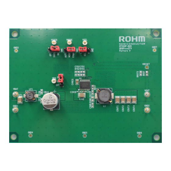
BD9P2x6EFV-C Series Evaluation Board
BD9P2x6EFV-TSB-001 (3.5 V to 40 V Input, 2.0 A)
Introduction
This user's guide will provide the necessary steps to operate the Evaluation Board of ROHM's BD9P2x6EFV-C series Buck
DC/DC converter which includes BD9P206EFV-C, BD9P236EFV-C, and BD9P256EFV-C. This includes the external parts,
operating procedures and application data.
Description
This Evaluation Board was developed for ROHM's single 440 kHz buck DC/DC converter BD9P2x6EFV-C series.
BD9P2x6EFV-C series is a current mode synchronous buck DC/DC converter with integrated POWER MOSFETs.
BD9P2x6EFV-C series accepts a power supply input range of 3.5 V to 40 V and generates a maximum output current of 2 A.
BD9P206EFV-C generates an output voltage range of 0.8 V to 8.5 V using external resistors. BD9P236EFV-C generates a
fixed output voltage of 3.3 V, and BD9P256EFV-C generates a fixed output voltage of 5.0 V.
Application
Automotive Powered Supplies
Consumer Powered Supplies
Recommended Operating Conditions
Parameter
Input Voltage
Output Voltage for BD9P206EFV-C
Output Voltage for BD9P236EFV-C
Output Voltage for BD9P256EFV-C
Output Current Range
Switching Frequency
Maximum Efficiency(BD9P236EFV-C)
Maximum Efficiency(BD9P256EFV-C)
(Note1) Although the minimum output voltage is configurable up to 0.8 V, it may be limited by the SW min ON pulse width. For
the same reason, although the maximum output voltage is configurable up to 8.5 V, it may be limited by the SW minimum OFF
pulse width.
© 2024 ROHM Co., Ltd.
Table 1. Recommended Operating Conditions
Min
Typ
3.5
-
(Note1)
0.8
-
-
3.3
-
5.0
-
-
-
440
-
92.9
-
94.7
User's Guide
Max
Units
40
V
Initial startup is 4.0 V or more
8.5
V
-
V
-
V
OCP_SEL = H : 1.5 A (Max)
2.0
A
OCP_SEL = L : 2.0 A (Max)
-
kHz
VIN = 12 V, Io = 0.53 A, Ta =
-
%
25 °C
-
%
VIN = 12 V, Io = 0.7 A, Ta = 25 °C
The
Conditions
67UG076E Rev.001
Sep.2024
Advertisement

Subscribe to Our Youtube Channel
Related Manuals for Rohm BD9P2 6EFV-C Series


Summary of Contents for Rohm BD9P2 6EFV-C Series
- Page 1 BD9P2x6EFV-TSB-001 (3.5 V to 40 V Input, 2.0 A) Introduction This user’s guide will provide the necessary steps to operate the Evaluation Board of ROHM’s BD9P2x6EFV-C series Buck DC/DC converter which includes BD9P206EFV-C, BD9P236EFV-C, and BD9P256EFV-C. This includes the external parts, operating procedures and application data.
- Page 2 (Caution) This Evaluation Board does not support hot plug. Do not perform hot plug test. (Note) If EN = High (EN short to VIN) before Power ON, the turn ON and turn OFF is controlled by VBAT only. © 2024 ROHM Co., Ltd. 67UG076E Rev.001 2/11 Sep.2024...
- Page 3 Select Spread Spectrum SSCG function OFF (LOW) Disable Spread Spectrum (Note) If setting is High, the terminal is shorted to VREG, and if setting is Low, the terminal is shorted to GND. © 2024 ROHM Co., Ltd. 67UG076E Rev.001 3/11 Sep.2024...
- Page 4 This pin is not connected to the chip. Use this as open. If this pin is used other (BD9P236EFV-C, than open and adjacent pins are expected to be shorted, please confirm if there N.C. BD9P256EFV-C) is any problem with the actual application. © 2024 ROHM Co., Ltd. 67UG076E Rev.001 4/11 Sep.2024...
- Page 5 REX (Note 2) 0 Ω 0201 0603 ROHM MCR006 Series REXN (Note 2) Open RRST (Note 3) 10 kΩ 0201 0603 ROHM MCR006 Series RRST2 (Note 3) Open RSNB Open CSNB Open © 2024 ROHM Co., Ltd. 67UG076E Rev.001 5/11 Sep.2024...
- Page 6 REX (Note 2) 0 Ω 0201 0603 ROHM MCR006 Series REXN (Note 2) Open RRST (Note 3) 10 kΩ 0201 0603 ROHM MCR006 Series RRST2 (Note 3) Open RSNB Open CSNB Open © 2024 ROHM Co., Ltd. 67UG076E Rev.001 6/11 Sep.2024...
- Page 7 The changes in the frequency characteristic are greatly affected by the type and the condition (temperature, etc.) of parts that are used, the wire routing and the layout of the PCB. Please confirm stability and responsiveness in actual application. © 2024 ROHM Co., Ltd. 67UG076E Rev.001 7/11 Sep.2024...
- Page 8 (Note 5) If the recommended parts on tables 4, 5 and 6 are not available anymore due to end of production, different parts will be used on the test board because the end of production parts are deprecated. © 2024 ROHM Co., Ltd. 67UG076E Rev.001 8/11 Sep.2024...
- Page 9 2oz(70μm) / 1oz (35μm) / 1oz (35μm) / 2oz(70μm) The layout of BD9P2x6EFV-C series is shown below. Figure 5 . Top Layer Layout (Top View) Figure 6. Middle1 Layer Layout (Top View) © 2024 ROHM Co., Ltd. 67UG076E Rev.001 9/11 Sep.2024...
- Page 10 BD9P2x6EFV-C User’s Guide Board Layout - continuation Figure 7. Middle2 Layer Layout (Top View) Figure 8. Bottom Layer Layout (Top View) © 2024 ROHM Co., Ltd. 67UG076E Rev.001 10/11 Sep.2024...
- Page 11 BD9P2x6EFV-C User’s Guide Revision History Revision Date Description Number 24. Sep. 2024 New release © 2024 ROHM Co., Ltd. 67UG076E Rev.001 11/11 Sep.2024...
- Page 12 Specific Applications). Unless otherwise agreed in writing by ROHM in advance, ROHM shall not be in any way responsible or liable for any damages, expenses, or losses incurred by you or third parties arising from the use of ROHM Products for Specific Applications.
Need help?
Do you have a question about the BD9P2 6EFV-C Series and is the answer not in the manual?
Questions and answers