Table of Contents
Advertisement
Quick Links
Advertisement
Table of Contents

Subscribe to Our Youtube Channel
Related Manuals for Rohm BD83A14EFV-M


Summary of Contents for Rohm BD83A14EFV-M
- Page 1 BD83A14EFV-M Evaluation Board REFLED004-EVK-001...
-
Page 2: High Voltage Safety Precautions
[8] Be sure to wear insulated gloves when handling is required during operation. After Use [9] The ROHM Evaluation Board contains the circuits which store the high voltage. Since it stores the charges even after the connected power circuits are cut, please discharge the electricity after using it, and please deal with it after confirming such electric discharge. - Page 3 BD83A14EFV-M Evaluation Board REFLED004-EVK-001 Introduction This user’s guide will provide the necessary steps to operate the Evaluation Board of ROHM’s BD83A14EFV-M LED Driver. This document includes the external parts, operating procedures and application data. Description This Evaluation Board was developed for ROHM’s LED Driver BD83A14EFV-M. BD83A14EFV-M is a white LED driver for LCD backlight.
-
Page 4: Evaluation Board Setup
Connect pulse generator to PWM-pin. It should be 100Hz to 25kHz and the minimum pulse width must be longer than 0.5μs. Turn on the power supply for +B-pin. Turn on the power supply for EN-pin. Turn on the pulse generator for PWM-pin. © 2022 ROHM Co., Ltd. 65UG067E Rev.001 2/10 Dec.2022... -
Page 5: Operation Mode Settings
D = 15.1 kΩ) ADIM_P ISET is the LED current setting resistor �� (Recommended operating condition:8.8kΩ to 53kΩ) is the ADIM_P pin input OnDuty �� (Recommended operating condition:18% to 100%) © 2022 ROHM Co., Ltd. 65UG067E Rev.001 3/10 Dec.2022... -
Page 6: Pin Configuration
BD83A14EFV-M-001 User’s Guide Pin configuration Figure 6. Pin configuration © 2022 ROHM Co., Ltd. 65UG067E Rev.001 4/10 Dec.2022... -
Page 7: Evaluation Board Schematic
BD83A14EFV-M-001 User’s Guide Evaluation board schematic Figure 7. Evaluation board schematic © 2022 ROHM Co., Ltd. 65UG067E Rev.001 5/10 Dec.2022... -
Page 8: Parts List
1608 10kΩ MCR03 series Resistor Rohm ROVP2 1608 360kΩ MCR03 series Resistor Rohm ROVP3 1608 10kΩ MCR03 series Resistor Rohm RISET1 1608 10kΩ MCR03 series Resistor Rohm RISET2 1608 0Ω Resistor © 2022 ROHM Co., Ltd. 65UG067E Rev.001 6/10 Dec.2022... - Page 9 Resistor 1608 0Ω Resistor RSYNCU 1608 0Ω Resistor RPWM 1608 0Ω Resistor JFAIL_EXT Open JPADIM_VCC1 Open JPADIM_VCC2 Open JFAIL_REG 1608 0Ω Resistor JPADIM_REG 1608 0Ω Resistor HTSSOP-B24 BD83A14EFV-M LED Dr Rohm © 2022 ROHM Co., Ltd. 65UG067E Rev.001 7/10 Dec.2022...
-
Page 10: Board Layout
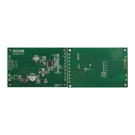
90X60mm Minimum copper width 0.15mm Minimum air gap 0.15mm Minimum hole size 0.3mm The layout of BD83A14EFV-M is shown below. (Top view) (Top view) Figure 9. 2nd layer layout Figure 8. Top layer layout (Top view) (Top view) (Top view) Figure 10. -
Page 11: Reference Application Data
Reference application data (Ta=25°C, Output voltage=34V, Iout=120mA x 4ch) Input voltage (V) Figure 12. Efficiency vs Input voltage -120 -180 1000 10000 100000 1000000 Frequency(Hz) Figure 13. Gain, Phase vs Frequency (VCC=12V) © 2022 ROHM Co., Ltd. 65UG067E Rev.001 9/10 Dec.2022... -
Page 12: Revision History
BD83A14EFV-M-001 User’s Guide Revision history Revision Date Description number 06. Dec. 2021 Initial release © 2022 ROHM Co., Ltd. 65UG067E Rev.001 10/10 Dec.2022... - Page 13 Products. ROHM does not grant you, explicitly or implicitly, any license to use or exercise intellectual property or other rights held by ROHM or any other parties. ROHM shall have no responsibility whatsoever for any dispute arising out of the use of such technical information.
Need help?
Do you have a question about the BD83A14EFV-M and is the answer not in the manual?
Questions and answers