Advertisement
Quick Links
Switching Regulator Series
Integrated MOSFET Single Synchronous
Buck DC/DC Converter
BD9E203FP4-Z Evaluation Board
BD9E203FP4-EVK-001 (12V Input, 5V Output, 2A)
Introduction
This user's guide will provide the necessary steps to operate the Evaluation Board of ROHM's BD9E203FP4-Z Single
Synchronous Buck DC/DC converter. This includes the external parts and operating procedures. For the reference application
data please refer to the datasheet.
Description
This Evaluation Board was developed for ROHM's single Synchronous buck DC/DC converter BD9E203FP4-Z.
BD9E203FP4-Z is a synchronous buck DC/DC converter with built-in low On Resistance power MOSFETs.
Z accepts a power supply input range of 4.5 V to 28 V and generates a maximum output current of 2 A. BD9E203FP4-Z
includes internal phase compensation. It achieves the high power density and offers a small footprint on the PCB by employing
small package.
Application
Home Appliance Products
Secondary Power Supply and Adapter Equipment
Telecommunication Devices
Recommended Operating Conditions
Parameter
Input Voltage
Output Voltage
Output Current Range
Switching Frequency
Maximum Efficiency
(Note 1) Tj must be 150 °C or less under the actual operating environment. Lifetime is derated at junction temperature greater
than 125 °C.
(Note 2) Please use within the range of VOUT ≥ VIN × 0.1 V.
© 2024 ROHM Co., Ltd.
Table 1. Recommended Operating Conditions
Min
Typ
4.5
-
0.7
-
0
-
-
350
-
95.5
User's Guide
Max
Units
28
V
V
x 0.8
V
(Note 2)
IN
2.0
A
-
kHz
VIN = 12.0 V, Vo = 5.0 V, Io =
-
%
0.7 A, Ta = 25 °C
The BD9E203FP4-
Conditions
67UG090E Rev.001
Apr.2024
Advertisement

Subscribe to Our Youtube Channel
Related Manuals for Rohm BD9E203FP4-EVK-001


Summary of Contents for Rohm BD9E203FP4-EVK-001
- Page 1 BD9E203FP4-EVK-001 (12V Input, 5V Output, 2A) Introduction This user’s guide will provide the necessary steps to operate the Evaluation Board of ROHM’s BD9E203FP4-Z Single Synchronous Buck DC/DC converter. This includes the external parts and operating procedures. For the reference application data please refer to the datasheet.
- Page 2 (Note 1) Enable pin’s initial setting is open. The IC’s power is controlled only by VIN, because EN is internally pulled-up to the internal regulator voltage by a 1 MΩ (Typ) resistor. © 2024 ROHM Co., Ltd. 67UG090E Rev.001 Apr.2024...
- Page 3 0.82 kΩ (1 %, 1/16 W) MCR01MZPF8200 ROHM Chip Resistor 1005 110 kΩ (1 %, 1/16 W) MCR01MZPF1103 ROHM Chip Resistor 1005 15 kΩ (1 %, 1/16 W) MCR01MZPF1502 ROHM Chip Resistor R0 (Note5) Short © 2024 ROHM Co., Ltd. 67UG090E Rev.001 Apr.2024...
- Page 4 (Note 6) If the recommended parts on tables 2, 3 and 4 are not available anymore due to end of production, different parts will be used on the test board because the end of production parts are deprecated. © 2024 ROHM Co., Ltd. 67UG090E Rev.001...
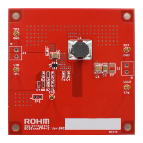
- Page 5 2oz(70μm) / 1oz (35μm) / 1oz (35μm) / 2oz(70μm) FR-4 1.6mm The layout of BD9E203FP4-Z is shown below: Figure 4. Top PCB Image Figure 5. Bottom PCB Image Figure 6. Top Layer Layout Figure 7. Middle1 Layer Layout © 2024 ROHM Co., Ltd. 67UG090E Rev.001 Apr.2024...
- Page 6 BD9E203FP4-Z User’s Guide Figure 8. Middle2 Layer Layout Figure 9. Bottom Layer Layout © 2024 ROHM Co., Ltd. 67UG090E Rev.001 Apr.2024...
- Page 7 BD9E203FP4-Z User’s Guide Revision History Revision Date Description Number 10. Apr. 2024 New release © 2024 ROHM Co., Ltd. 67UG090E Rev.001 Apr.2024...
- Page 8 Specific Applications). Unless otherwise agreed in writing by ROHM in advance, ROHM shall not be in any way responsible or liable for any damages, expenses, or losses incurred by you or third parties arising from the use of ROHM Products for Specific Applications.
Need help?
Do you have a question about the BD9E203FP4-EVK-001 and is the answer not in the manual?
Questions and answers