
Related Manuals for ESAB A6 Slide


Summary of Contents for ESAB A6 Slide
- Page 1 A6 Slide 101103105102021104022100020040060 Bruksanvisning Käyttöohjeet Brugsanvisning Instruction manual Bruksanvisning Betriebsanweisung 0443 394 060 2006- -07- -13 Valid for serial no. 452- -xxx- -xxxx...
- Page 2 SVENSKA ..........DANSK .
- Page 3 - - 3 - -...
-
Page 4: Table Of Contents
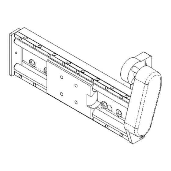
..............2.2 The A6 slide consists of: . -
Page 5: Safety
SAFETY Users of ESAB servo slides have the ultimate responsibility for ensuring that anyone who works on or near the servo slide observes all the relevant safety regulations. The following recommendations should be observed in addition to the standard re- gulations that apply to the work place. - Page 6 WARNING ARC WELDING AND CUTTING CAN BE INJURIOUS TO YOURSELF AND OTHERS. TAKE PRECAUTIONS WHEN WELDING. ASK FOR YOUR EMPLOYER’S SAFETY PRACTICES WHICH SHOULD BE BASED ON MANUFACTURER’S HAZARD DATA. ELECTRIC SHOCK - - Can kill Install and earth the welding unit in accordance with applicable standards. Do not touch live electrical parts or electrodes with bare skin, wet gloves or wet clothing.
-
Page 7: Technical Description
TECHNICAL DESCRIPTION General The A6 slide is designed to carry and transfer welding heads of different types of welding plants. The slide can be mounted across the weld joint -- single or in a cross saddle -- for adjustment or joint tracking. It can also be mounted along the weld joint to bring about a welding movement. -
Page 8: Technical Data
13,2 15,0 16,7 18,5 21,9 25,4 30,9 38,8 A6 Slide Max control voltage 42 V DC Max speed at 42 V DC 70 cm/min (175 cm/min with reversed gear wheels in transmission) Continuous A--weighted noise pressure 42 dB Play of runner in the longitudinal direc-... -
Page 9: The Linear Bearing Of The Runner
The linear bearing of the runner Max permissible momemt--free load on the runner of the slide is 150 kg irrespective of the mounting position of the slide. Max permissible moment--generating load on the runner of the slide depends on the mounting position. - Page 10 Examplel 1: An A6 SFD1 automatic welding machine is mounted on a standing cross saddle. Note that the wire drum and the drum holder are mounted on th slide profile of the vertical slide. Example 1a: The load on the vertical slide is about 43 kg. The centre of gravity (TP1) is displaced 0,35 m from the runner of the vertical slide in the z direction.
-
Page 11: The Distance Between The Fixation Of The Slide Profile And The Line Of Application Of The Load
The distance between the fixation of the slide profile and the line of application of the load Max permissible forces on the mounting screws of the slide profile limits the distance (l) between the mounting screws and the application line of the load. At standing horizontal mounting it is assumed that the tightening moment is 48 Nm for an M10 screw and 84 Nm for an M12 screw (friction joint). -
Page 12: Deformation Of The Slide Profile Under Load
Deformation of the slide profile under load When loaded, the slide profile is deformed (bent, twisted) so that the position of the centre of gravity of the load is changed. The deflection (d) depends on: The size of the load The mounting position of the slide The distances a, L and x (y, z) are defined in the following fig. - Page 13 Example 4: An automatic welding machine is fitted on a vertical cross saddle. The load on the vertical slide is 43 kg. The position of the centre of gravity is at the dis- tance z=0,35 m from the runner. The load on the horizontal slide is 100 kg and its centre of gravity is at the distance z=0,17 m from the runner.
- Page 14 Lying horizontal mounting. Change of the centre Lying horizontal mounting, Change of gravity in the Y- -direction. The slide profile of the centre of gravity in the X- - bends. direction. The slide profile twists. Example 5: A lying horizontal slide with L = 0.4 m is loaded with 50 kg.
-
Page 15: Slide Transfer
Slide transfer Current consumption of electric motor and limit to self- - braking The current consumption is linearly depending on the load. In the table the current consumption is indicated for different gear ratios at idle running, full load and sliding . The table shows max load at self--braking of the motor worm gear. -
Page 16: Installation
INSTALLATION General The installation must be executed by a professional. WARNING! Incorrect installation of the servo slide or incorrect fitting of the load on the slide can cause damage to the machine and injure people. Connections of the runner For the attachement of the load there are four M12 holes on the runner at a spacing of 60 mm for M12 screws or M10 Allen screws with washer. -
Page 17: Recommended Way Of Lifting Servo Slides
Recommended way of lifting servo slides The dead weight of most slides is so low that manual lifting can take place. For slides with an adjustable length over 540 mm and for assembled cross saddles an approved lifting device should be used. NOTE. -
Page 18: Operation
OPERATION General Caution: Have you read and understood the safety information ? You must not operate the machine before then ! General safety regulations for the handling of the equipment can be found on page 85. Read through before you start using the equipment! WARNING Rotating parts can cause injury, take great care. - Page 19 Adjusting the friction moment Tighten the centre screw 3/4 turn after the position where the cup springs start working. The friction moment can be decreased as necessary (for instance to lessen the friction current) by tightening the centre screw less than 3/4 turn. NB.
-
Page 20: Maintenance
MAINTENANCE General Note: All warranty undertakings given by the supplier cease to apply if the customer attempts to rectify any faults on the machine during the warranty period. Daily: Blow the slide clean from flux and dust. Every month: Check the tooth belt and replace as necessary. Note that the belt must be replaced at least every 5 years. -
Page 21: Replacing The Linear Bearings
Replacing the linear bearings The linear bearings of the slide consist of two steel shafts (4) and four ball bushings (12). - - 101 - - fgb5m1ea... - Page 22 Replacing the ball bushings (12) Dismount the belt pulley (1), the wedge (2), the ball bearing nut with locking washer (3) and the end washer (9) from the ball screw. Draw out the runner (6) with ball screw (5) from the steering steel shafts (4).
-
Page 23: Ordering Of Spare Parts
Fit the remaining parts. ORDERING OF SPARE PARTS Spare parts are ordered through your nearest ESAB representative, see back cover. When ordering spare parts, please state machine type and number as well as desig- nation and spare part number as shown in the spare parts list on page 125. - Page 24 ESAB subsidiaries and representative offices Europe Asia/Pacific Representative offices NORWAY AS ESAB AUSTRIA BULGARIA CHINA Larvik ESAB Ges.m.b.H ESAB Representative Office Shanghai ESAB A/P Tel: +47 33 12 10 00 Vienna- -Liesing Sofia Shanghai Fax: +47 33 11 52 03...
Need help?
Do you have a question about the A6 Slide and is the answer not in the manual?
Questions and answers