ESAB A6 Mastertrac Instruction Manual
A6 tfe2
Hide thumbs
Also See for A6 Mastertrac:
- Instruction manual (78 pages) ,
- Manual (50 pages) ,
- Instruction manual (78 pages)
Table of Contents
Advertisement
Quick Links
Download this manual
See also:
Instruction Manual
Advertisement
Table of Contents

Related Manuals for ESAB A6 Mastertrac


Summary of Contents for ESAB A6 Mastertrac
- Page 1 A6 Mastertrac A6 TFE2 Instruction manual 0449 468 101 GB 2007- -07- -12 Valid for serial no. 709...
- Page 2 ESAB AB, Welding Equipment, 695 81 Laxå, Sweden, declares under sole responsibility that the au- tomatic welding machine A6 Mastertrac (A6 TFE2) from serial number 709 xxx xxxx (2007 week 09) is designed and tested in conformity with the published standards in accordance with the conditions in the directives (98/37/EC) and (2004/108/EC).
-
Page 3: Table Of Contents
1 SAFETY ............2 INTRODUCTION . -
Page 4: Safety
SAFETY Users of ESAB welding equipment have the ultimate responsibility for ensuring that anyone who works on or near the equipment observes all the relevant safety precautions. Safety precautions must meet the requirements that apply to this type of welding equipment. The following recommen- dations should be observed in addition to the standard regulations that apply to the workplace. - Page 5 WARNING ARC WELDING AND CUTTING CAN BE INJURIOUS TO YOURSELF AND OTHERS. TAKE PRECAU- TIONS WHEN WELDING. ASK FOR YOUR EMPLOYER’S SAFETY PRACTICES WHICH SHOULD BE BASED ON MANUFACTURERS’ HAZARD DATA. ELECTRIC SHOCK - - Can kill Install and earth the welding unit in accordance with applicable standards. Do not touch live electrical parts or electrodes with bare skin, wet gloves or wet clothing.
-
Page 6: Introduction
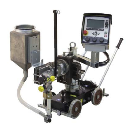
The position of welding head can be set horizontally and vertically with the linear slides. Angular movement is adjusted with the angular slide. The automatic welding machine is intended for use in combination with the A2--A6 Process Controller (PEH) and ESAB’s welding power sources LAF or TAF. Welding method 2.2.1 Submerged- - arc welding The weld bead is protected by a cover of flux during the welding. -
Page 7: Technical Data
Technical data A6 TFE2 Supply voltage 42 V AC Rated load 100 % 1500 A DC/AC Electrode dimensions: solid single wire 3,0--6,0 mm flux--cored wire 3,0--4,0 mm twin wire 2x2,0--3,0 mm Electrode feed rate, max. 4 m/min Brake drum braking torque 1,5 Nm Speed of travel 0,1--2,0 m/min... -
Page 8: Description Of Main Components
Description of Main Components 2.6.1 Carriage The carriage is provided with 4--wheel drive. The carriage can be secured by way of the locking lever (1). 2.6.2 Wire Feed Unit The unit is used for guiding and feeding the welding wire down into the connector. 2.6.3 Manual Slides The horizontal and vertical position of the welding head is adjusted by way of linear... -
Page 9: Installation
INSTALLATION General The installation must be executed by a professional. WARNING Rotating parts can cause injury, take great care. Mounting 3.2.1 Wire drum (Accessories) Wire drum (1) is mounted on the brake hub (2). Check that the carrier (3) is pointing upwards. NOTE! The maximum angle for the wire bobbin is 25°. -
Page 10: Connections
Connections 3.4.1 General The A2--A6 Process Controller (PEH) is to be connected by a qualified person. For the connection of A6 GMD, see instruction manual 0443 403 xxx. For the connection of A6 PAK, see instruction manual 0443 405 xxx. 3.4.2 Submerged arc welding (SAW) 1. -
Page 11: Operation
OPERATION General Caution: Have you read and understood the safety information ? You must not operate the machine before then ! General safety regulations for the handling of the equipment can be found on page 4. Read through before you start using the equipment! Select wire type and flux powder or shielding gas so that the weld material is as close as possible to the analysis of the base metal. -
Page 12: Loading The Welding Wire
Loading the welding wire 1. Mount the wire drum according to the instructions on page 9. 2. Check that feed roller (1) and contact jaw or contact tip (3) are of the correct dimension for the selected wire size. 3. For A6 TF (Twin): Feed the wire through the wire guide (8). -
Page 13: Changing The Feed Roller
Changing the feed roller Single wire Release the knobs (3) and (4). Release the hand wheel (2). Change the feed roller (1). They are marked with their respective wire sizes. Twin wire (Twin- -arc) Change the feed roller (1) with twin grooves in the same way as for single wire. NOTE! The pressure roller (5) must also be changed. -
Page 14: Contact Equipment For Submerged--Arc Welding
Contact equipment for submerged- -arc welding For single wire 3.0 - - 6.0 mm. Heavy duty (D35) Use the straightener (3), connector (1) D35 with contact jaws (2). Assemble one contact jaw with the M5 bolts provided, in the fixed contact tip (a). Assemble the other contact jaw in the free half of the two--piece connector (b) under the bolt (8) and tighten down hard to ensure that a good contact is achieved between... -
Page 15: Refilling With Flux Powder
For twin wires 2 x 1.2 - - 2.0 mm, Light Twin (D35) (Accessories) Use the straightener (3), connector (1) D35 with twin adapter (9) and 2 contact tips (2) (M6 threads) and separate fine wire straightener (4) with two guide tubes (6). For twin wires <... -
Page 16: Maintenance
MAINTENANCE General Note: All warranty undertakings given by the supplier cease to apply if the customer attempts to rectify any faults on the machine during the warranty period. NB! Before doing any kind of maintenance work, make sure the mains is disconnected. -
Page 17: Troubleshooting
Use cables with a larger cross--section or use parallel cables. ORDERING OF SPARE PARTS Spare parts are ordered through your nearest ESAB representative, see back cover. When ordering spare parts, please state machine type and number as well as desig- nation and spare part number as shown in the spare parts list on page 21. -
Page 18: Wear Components
Wear components Feed rollers SAW tubular wire Part no D (mm) 0146 024 880 0,8--1,6 0146 024 881 2,0--4,0 Pressure rollers SAW tubular wire Part no D (mm) 0146 025 880 0,8--1,6 0146 025 881 2,0--4,0 Contact jaws SAW HD (D35) Part no D (mm) 0265 900 880... -
Page 19: Dimension Drawing
Dimension drawing - - 19 - - ffb9dim... - Page 20 - - 20 - - sida...
-
Page 21: Spare Parts List
Spare parts list Edition 2007- -07- - 12 Ordering no. Denomination Notes 0334 191 882 Automatic welding machine A6 TFE2 - - 21 - - spareFram... - Page 22 Item Ordering no. Denomination Notes 0334191882 Automatic welding machine A6 TFE2 0443741880 Control box PEH, see separate manual 0146967880 Brake hub 0334457880 Wire guide 0334184001 Plate 0147639881 Wire straightener (left mounted) 0334170001 Clamping ring 0417959880 Contact jaw tube L=220 0334183881 Carriage 0334171001 Plate...
- Page 23 - - 23 - - f334191s...
- Page 24 Item Ordering no. Denomination Notes 0147639880 Straightener (right mounted) 0156449001 Clamp 0215503601 Insulating sleeve 0156530001 Clamp half 0212900001 Spacer screw 0215201209 Sealing, O- -ring D11.3x2.4 0218400801 Pressure roller arm 0218810181 Handwheel, insulated 0218810182 Handwheel, insulated 0332408001 Stub shaft 0153148880 Pressure roller 0415498001 Pressure roller, upper 0212902601...
- Page 25 Item Orderingno. Denomination Remarks 0147639881 Straightener (left mounted) 0156449001 Clamp 0215503601 Insulating sleeve 0156530001 Clamp half 0212900001 Spacer screw 0215201209 Sealing, O- -ring D11.3x2.4 0218400801 Pressure roller arm 0218810181 Handwheel, insulated 0218810182 Handwheel, insulated 0332408001 Stub shaft 0153148880 Pressure roller 0415498001 Pressure roller, upper 0212902601...
- Page 26 Item Ordering no. Denomination Notes 0417959880 Contact jaw tube L = 220 mm 0443344880 Contact tube L = 220 mm 0443372001 Fitting bolt 0219504307 Cup spring d20/10.2, T=1.1 0417979001 Ring - - 26 - - f417959s...
- Page 27 Item no. Ordering no. Denomination Notes 0334183881 Carriage 0334295880 Handle 0449205880 Guide arm 0229202280 Wheel 0219501013 Spring washer d18,1/10,2 0334198880 Front shaft with sprocket 0334264001 Flange bearing unit 0218201502 Chain 1/2”x4,88 0218201602 Chain lock simple 1/2”x4,88 0334160001 Stub shaft 0334163880 Sprocket 0334162880 Sprocket...
- Page 28 Item Ordering no. Denomination Notes 0147649881 Flux Hopper 0154007001 Flux hopper 0148837001 Window (a6 flux hopper) 0147645001 Mounting 0153347880 Flux valve 0215201232 Sealing, O- -ring 69,2x5,7 0020301780 Flux strainer 0443383002 Flux hose L=500 - - 28 - - f147649s...
- Page 29 Item Orderingno. Denomination Remarks 0154465880 Slide, manually operated L=90 0154464001 Slide frame 0154463880 Carriage with slide rails 0190509485 Stop screw M10x10 0154458001 End piece 0211102957 Roll pin D5x20 0154461001 Lead screw 0190531201 Ball bearing SKF 3201 0154456001 Lock nut 0154457001 Ball bearing cap 0334537001 Handle crank...
- Page 30 Item Ordering no. Denomination Notes 0153299880 Flux nozzle complete 0153290002 Holder for flux pipe 0153296001 Flux pipe, bent 0153425001 Wheel - - 30 - - f153299s...
- Page 32 ESAB subsidiaries and representative offices Europe Asia/Pacific Representative offices NORWAY AS ESAB AUSTRIA BULGARIA CHINA Larvik ESAB Ges.m.b.H ESAB Representative Office Shanghai ESAB A/P Tel: +47 33 12 10 00 Vienna- -Liesing Sofia Shanghai Fax: +47 33 11 52 03...
Need help?
Do you have a question about the A6 Mastertrac and is the answer not in the manual?
Questions and answers