
Related Manuals for WEG CP-D


Summary of Contents for WEG CP-D
- Page 1 Motors | Automation | Energy | Transmission & Distribution | Coatings CP-D Emergency Stop Control User’s Manual...
- Page 3 User’s Manual Série: CP-D 301 Language: English Document: 10010034430 / 00 Publication Date: 02/2023...
- Page 4 Summary of Reviews The information below describes the revisions made to this manual. Version Review Description First edition...
-
Page 5: Table Of Contents
Summary 1 ABOUT THIS DOCUMENT ............... 1-1 1.1 OBJECTIVE ....................1-1 1.2 AUTHORISED PERSONNEL ..............1-1 1.3 SYMBOLS USED IN THIS MANUAL ............1-1 1.4 APPROPRIATE USE ................1-1 1.5 EXCLUSION OF LIABILITY ..............1-1 2 DESCRIPTION ................... 2-1 2.1 DESTINATION AND USE ................. 2-1 2.2 TECHNICAL INFORMATION .............. -
Page 6: About This Document
1.5 EXCLUSION OF LIABILITY The device’s manufacturer excludes itself from the liability of bad handling or misuse which could result into dangerous event. It is not allowed to have the device opened or even repaired by non authorized personnel. CP-D | 1-1... -
Page 7: Description
1 normally closed contact Contact capacity 4.5 A - 30 Vdc / 200 W - 250 Vac Utilisation category to EN 60947-5-1 AC-15 / DC-13: EN 60947-5-1 Dimensions (H/W/L) 113.1 mm x 97 mm x 22.7 mm CP-D | 2-1... -
Page 8: Safety Levels
Description 2.3 SAFETY LEVELS IEC 60 204-1, ISO 13850, EN 60947-5-1, Standards EN ISO 13849-1, IEC 61508, EN 62061 PL Category Control Category PFH-Value 2,82 E-10 1/h Service Life 20 years 2-2 | CP-D... -
Page 9: Installation And Connections
For a proper connection of the inputs, refer to the appendix of this manual and look for the figures 1 and 2 of that chapter. ATTENTION! It is mandatory to have the contacts properly connected in order to avoid misuses and even to guarantee contacts’ and device’s integrity. CP-D | 3-1... -
Page 10: Operational Principle And Settings
If one or both inputs, S11-S12 or S21-S22, are deactuated, the outputs switch to the off state immediately. For a new cycle (new drive), both inputs must be deactuated, to deactivate the outputs, and then actuated back again. Afterwards, the reset button must be actuated. CP-D | 4-1... -
Page 11: Led Functioning
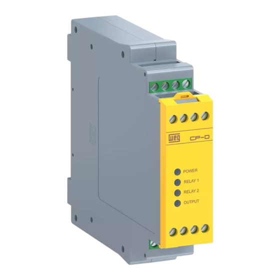
Operational Principle and Settings 4.3 LED FUNCTIONING Power Power Supply Voltage Channel 1 signalling Channel 2 signalling Output contact’s activation 4-2 | CP-D... -
Page 12: Setup And Maintenance
Therefore, they cannot be interconnected (changed to single channel input) or the functionality of the device will be corrupted. The circuit shall not activate the outputs in case it is powered on with inputs actuated, thus preventing unintentional activation. CP-D | 5-1... -
Page 13: Dismounting And Disposal
Pull the metallic latch, below the enclosure, towards you (using preferentially a screw driver) and pull the device up. 6.2 DISPOSAL As this device should be handled and carried with care, it should be disposed likewise. It should be disposed in accordance under national prescriptions and legislations. CP-D | 6-1... -
Page 14: Appendix
This control system recognizes wire breakage and earth faults in the central circuit. Likewise, the cross-wire short circuits between the control circuits are detected. Reset Safety relays Start Input Control Supply circuit Figure 7.1: Internal blocks’ diagram CP-D | 7-1... - Page 15 Appendix Note: Start Utilization of feedback function Fuse Y1 Y2 13 23 33 41 24 Vdc CP-D S12 S11 14 24 34 Emergency button Figure 7.2: Example of configuration 7-2 | CP-D...
- Page 16 Appendix S21S22 Sensor 1 Figure 7.3: Gate sensor CP-D | 7-3...
-
Page 17: Declaration Of Conformity
Declaration of Conformity 8 DECLARATION OF CONFORMITY 8.1 CE CP-D | 8-1... -
Page 18: Ukca
Declaration of Conformity 8.2 UKCA Manufacturer: WEG Equipamentos Elétricos S.A. Av. Prefeito Waldemar Grubba, 3000 89256-900 - Jaraguá do Sul – SC – Brazil www.weg.net 8-2 | CP-D...
Need help?
Do you have a question about the CP-D and is the answer not in the manual?
Questions and answers