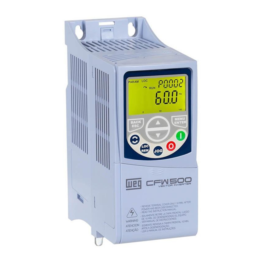
WEG CFW500 Manual
- User manual (185 pages) ,
- Applications manual (36 pages) ,
- Installation, configuration and operations manual (32 pages)
Advertisement
ABOUT THE MANUAL
This manual provides the necessary information for the configuration of Solar Pump Drive application developed with the CFW500 inverter SoftPLC function. This application manual must be used together with the CFW500 user's manual, the SoftPLC function manual and the WLP or WPS software manual.
ABBREVIATIONS AND DEFINITIONS
| PLC | Programmable Logic Controller |
| CRC | Cycling Redundancy Check |
| RAM | Random Access Memory |
| USB | Universal Serial Bus |
| WLP | Ladder Language Programming Software (CFW500 G1) |
| WPS | Ladder Language Programming Software (CFW500 G2) |
NUMERICAL REPRESENTATION
Decimal numbers are represented by means of digits without suffix. Hexadecimal numbers are represented with the letter 'h' after the number.
 NOTE! This version of the manual contains the default parameterization for the CFW500 G2 (V3.5x) with application version V2.xx (P1010). |
QUICK PARAMETER REFERENCE
| Parameter | Description | Adjustable Range | Application Default: 60Hz (50Hz) | User Setting | Prop. | Groups |
| P0100 | Acceleration Time | 0.1 to 999.0 s | 10.0 s | BASIC | ||
| P0101 | Deceleration Time | 0.1 to 999.0 s | 10.0 s | BASIC | ||
| P0133 | Minimum Speed | 0.0 to 500.0 Hz | 40.0 (30.0) Hz | BASIC | ||
| P0134 | Maximum Speed | 0.0 to 500.0 Hz | 60.0 (50.0) Hz | BASIC | ||
| P0136 | Manual Torque Boost | 0.0 to 30.0% | According to inverter model | V/F | MOTOR, BASIC | |
| P0142 | Maximum Output Voltage | 0.0 to 100.0% | 100.0% | cfg V/F | ||
| P0143 | Intermediate Output Voltage | 0.0 to 100.0% | 60.0% | cfg V/F | ||
| P0144 | Minimum Output Voltage | 0.0 to 100.0% | 28.0% | cfg V/F | ||
| P0202 | Type of Control | 0 to 5 | 0 (1) = V/F | cfg | STARTUP | |
| P0205 | Main Display Parameter | 2 = Speed in rpm 3 = Motor Current 4 = DC Link Voltage 5 = Frequency in Hz | 5 = Output Freq. | HMI | ||
| P0206 | Secondary Display Parameter | 4 = DC Link Voltage | HMI | |||
| P0207 | Parameter for Bar | 3 = Motor Current | HMI | |||
| P0208 | Ref. Eng. Scale | 0 to 65535 | 600 | HMI | ||
| P0209 | Ref. Eng. Unit | 3 = rpm 13 = Hz | 13 = Hz | HMI | ||
| P0210 | Ref. Indication Form | 0 to 7 | 1 = wxy.z | HMI | ||
| P0216 | HMI Backlight | 0 to 1 | 0 = Off | cfg | HMI | |
| P0220 | LOC/REM Selection Source | 0 to 11 | 1 = Always Remote | cfg | I/O | |
| P0222 | REM Reference Sel. | 0 to 17 | 12 = SoftPLC | cfg | I/O | |
| P0226 | REM Rotation Selection | 0 to 12 | 0 = Clockwise | cfg | I/O | |
| P0227 | REM Run/Stop Selection | 0 to 5 | 1 = DIx | cfg | I/O | |
| P0228 | REM JOG Selection | 0 to 6 | 0 = Disable | cfg | I/O | |
| P0230 | Dead Zone (AIs) | 0 to 1 | 1 = Active | cfg | I/O | |
| P0231 | AI1 Signal Function | 8 = Pressure PID Feedback | 1 = Not Used | I/O | ||
| P0233 | AI1 Input Signal | 0 = 0 to 10 V 1 = 4 to 20 mA | 0 = 0 to 10 V | I/O | ||
| P0235 | AI1 Input Filter | 0.00 to 16,00 | 0,30 s | I/O | ||
| P0236 | AI2 Signal Function | 9 = Solar Sensor Detector 10 = Control Setpoint | 1 = Not Used | cfg | I/O | |
| P0238 | AI2 Input Signal | 0 to 3 | 0 = 0 to 10 V | cfg | I/O | |
| P0251 | AO1 Signal Function | 21 = Repeat AI1 | 2 = Real Speed | cfg | I/O | |
| P0263 | DI1 Input Function | 0 to 53 | 1 = Run / Stop | cfg | I/O | |
| P0264 | DI2 Input Function | 40 = Pressure Control 42 = Power by Group or Network | 40 = Pressure Control | cfg | I/O | |
| P0265 | DI3 Input Function | 41 = 1st DI for Control Setpoint Selection 42 = Power by Group or Network | 41 = 1st DI for Control Setpoint Selection | cfg | I/O | |
| P0266 | DI4 Input Function | 41 = 2nd DI for Control Setpoint Selection 42 = Power by Group or Network | 41 = 2nd DI for Control Setpoint Selection | cfg | I/O | |
| P0275 | DO1 Output Function | 37 = Triggers External Power | 11 = Run | I/O | ||
| P0276 | DO2 Output Function | 2 = F > Fx | I/O | |||
| P0277 | DO3 Output Function | 0 = Not Used | I/O | |||
| P0296 | Line Rated Voltage | 0 to 7 | According to inverter model | ro, cfg | READ | |
| P0320 | Flying Start/Ride-Through | 0 to 3 | 3 = Ride-Through | cfg | ||
| P0331 | Voltage Ramp | 0.2 to 60.0 s | 10.0 s | V/f | ||
| P0339 | Output Voltage Compensation in V/f | 0 to 1 | 1 = Active | cfg | ||
| P0340 | Auto-Reset Time | 0 to 255 s | 255 s | |||
| P0400 | Motor Rated Voltage | 200 to 600 V | According to inverter model | cfg | MOTOR, STARTUP | |
| P0401 | Motor Rated Current | 0.0 to 400.0 A | According to inverter model | cfg | MOTOR, STARTUP | |
| P0402 | Motor Rated Speed | 0 to 30000 rpm | According to inverter model | cfg | MOTOR, STARTUP | |
| P0403 | Motor Rated Frequency | 0 to 500.0 Hz | (60.0 Hz) 50.0 Hz | cfg | MOTOR, STARTUP | |
| P1001 | Command for SoftPLC | 0 to 5 | 1 = Run Program | SPLC | ||
| P1010 | Solar Pump Drive Application Version | 0.00 to 10.00 | ro | SPLC | ||
| P1011 | Current Tracking Setpoint | 0 to 1000 V | ro | SPLC | ||
| P1012 | Actual Pressure Setpoint / Speed | 0.0 to 4000.0 [Eng. Un.1] | ro | SPLC | ||
| P1013 | Output Pressure | 0.0 to 300.0 | ro | SPLC | ||
| P1014 | Operating Time CFW500 | 0 to 6553.5 h | ro | SPLC | ||
| P1015 | Counter kWh | 0 to 65535 kWh | ro | SPLC | ||
| P1016 | Remaining Time to a new Start Attempt | 0 to 3600 s | - | ro | SPLC | |
| P1017 | Deviation Stopping Value of AI2 | 0.0 to 100.0% | 0.0% | SPLC | ||
| P1019 | Increment Rate MPPT | 1 to 40 | 5 | SPLC | ||
| P1022 | Minimum Setpoint Vdc | 0 to 1000 V | 250 V | SPLC | ||
| P1023 | Maximum Setpoint Vdc | 0 to 1000 V | 400 V | SPLC | ||
| P1024 | PID Proportional Gain Vdc | 0.000 to 32.000 | 1.000 | SPLC | ||
| P1025 | PID Integral Gain Vdc | 0.00 to 32.00 | 20.00 | SPLC | ||
| P1026 | PID Derivative Gain Vdc | 0.000 to 32.000 | 0.00 | SPLC | ||
| P1027 | Starting Time | 0 to 3600 s | 60 s | SPLC | ||
| P1028 | Enable Starting Value of AI2 | 0.0 to 100.0% | 0.0% | SPLC | ||
| P1029 | Actuation Value DOx | 0.0 to 100.0% | 0.0% | SPLC | ||
| P1030 | Pressure Control | 0 = Manual 1 = Automatic 2 = Dix Selection 3 = Disabled | 3 = Disabled | SPLC | ||
| P1031 | Pressure Sensor Scale | 0.0 to 300.0 | 10.0 | SPLC | ||
| P1032 | PID Proportional Gain Pressure | 0.000 to 32.000 | 1.000 | SPLC | ||
| P1033 | PID Integral Gain Pressure | 0.00 to 320.00 | 10.00 | SPLC | ||
| P1034 | PID Integral Gain Pressure | 0.000 to 32.000 | 0.000 | SPLC | ||
| P1035 | Pump Motor Speed below which Solar Pump Drive goes to Sleep Mode | 0.0 to 4000.0 [P0209] | 0.0 [P0209] | SPLC | ||
| P1036 | Time Delay for Solar Pump Drive goes to Sleep Mode | 1 to 65000 s | 10 s | SPLC | ||
| P1037 | Control Process Variable Deviation for Solar Pump Drive to Wake Up | 0.0 to 300.0 | 0.0 | SPLC | ||
| P1038 | Cloud/Load Controller Activation Level | 0.0 to 100.0% | 1.0% | SPLC | ||
| P1039 | Cloud/Load Controller Gain | 0.00 to 10.00 | 1.00 | SPLC | ||
| P1040 | Time Delay for Dry Pump Fault (F765) | 0 to 65000 s | 0 s | SPLC | ||
| P1041 | Motor Speed for Dry Pump | 0.0 to 4000.0 [P0209] | 54.0 (45.0) [P0209] | SPLC | ||
| P1042 | Motor Current Percentage for Dry Pump | 0.1 to 100.0% | 45.0% | SPLC | ||
| P1043 | Time Reset Fault for Dry Pump | 0 to 720 min | 0 min | SPLC | ||
| P1044 | Minimum Output Pressure | 0.0 to 300.0 | 0.0 | SPLC | ||
| P1045 | Minimum Fault Pressure Time | 0 to 3200 s | 0 s | SPLC | ||
| P1046 | Maximum Output Pressure | 0.0 to 300.0 | 10.0 | SPLC | ||
| P1047 | Maximum Fault Pressure Time | 0 to 3200 s | 0 s | SPLC | ||
| P1048 | DOx Normally Closed | 0 to 1 | 0 | SPLC | ||
| P1049 | DOx Actuation Time | 0 to 65000 s | 0 s | SPLC | ||
| P1051 | Control Setpoint 1 | 0.0 to 4000.0 [Eng. Un.1] | 60.0 (50.0) | SPLC | ||
| P1052 | Control Setpoint 2 | 0.0 to 4000.0 [Eng. Un.1] | 1.5 | SPLC | ||
| P1053 | Control Setpoint 3 | 0.0 to 4000.0 [Eng. Un.1] | 1.5 | SPLC | ||
| P1054 | Control Setpoint 4 | 0.0 to 4000.0 [Eng. Un.1] | 1.5 | SPLC | ||
| P1059 | Operation (P1014) time and kWh (P1015) Reset | 0 = Not Used 1 = Resets Time Counter 2 = Reset kWh | 0 | SPLC |
| NOTE! To load the factory default set parameter P0204 to "7". |
FAULTS AND ALARMS
| Fault / Alarm | Description | Possible Causes |
| F021: Undervoltage on the DC Link | Undervoltage fault on the intermediate circuit. | Low voltage supply; check if the data on the inverter label comply with the power supply and parameter P0296. Supply voltage too low (AC generator or DC Solar Panel), producing voltage on the DC Link (P0004) below the minimum value: Ud < 200 Vdc in 200-240 Vac (P0296 = 0). Ud < 360 Vdc in 380-480 Vac (P0296 = 1, 2, 3 or 4). Ud < 500 Vdc in 500-600 Vac (P0296 = 5, 6 or 7). Phase fault in the input. Fault in the pre-charge circuit. |
| A0163: Signal Fault AIx 4..20 mA | Analog input signal AIx at 4 to 20 mA or 20 to 4 mA is below 2 mA. | Current signal on the analog input AIx interrupted or null. Error in the parameterization of analog input AIx |
| A750: Sleep Mode Active | It indicates that the Solar Pump Drive is in the sleep mode | Value of the pump motor speed is below the threshold programmed in P1035 during the time programmed in P1036. |
| A752: Starting Time | It indicates that the time between start attempts has started, the remaining time to the new start attempt can be followed in P1016. | Starting Time was due to lack of Solar Drive power (low power on solar panels) |
| A754: DC Checking Routine | It indicates that the drive is trying to accelerate to minimum speed and checking the DC bus behavior. | DC Bus checking alarm occurs at each start attempt when there is no measurement of a Solar Detection Sensor (AI2). |
| A756: Low Level Solar Detection | It indicates that there is Low Solar radiation (AI2). | The system is attempting to start with a low-level measurement of a Solar Detection Sensor (AI2). |
| F761: Minimum Pressure | Minimum system pressure failure. | The system pressure is below the value of P1044 for the time programmed in P1045. |
| F763: Maximum Pressure | Maximum system pressure failure. | The system pressure is above the value of P1046 for the time programmed in P1047. |
| F765: Dry Pump | It indicates that the pump was stopped due to dry pump protection. | During a time (P1040) the value of the pump motor speed remains above of the threshold programmed in P1041 and motor torque remains below the threshold programmed in P1042. |
| F799 Incompatible Firmware Version | It indicates that the Firmware is incompatible with the Solar Pump Application. | The firmware of the product (P0023) is incompatible with the Solar Pump Application version. Compatible Versions: CFW500 G1 (P0023 < v3.5x -> P1010=v1.xx) CFW500 G2 (P0023 > v3.5x -> P1010=v2.xx) |
PHOTOVOLTAIC WATER PUMPING SYSTEM
This document presents information necessary to configure all the functions of the frequency inverter CFW500. Applied to photovoltaic water pumping systems. For more detailed information on the function of expansion and communications accessories, refer to the following manuals:
- CFW500 Frequency Inverter Documentation;
- Solar Pump Drive Installation Guide;
- CFW500 SoftPLC Manual;
- CFW500 Programming Manual;
- CFW500-CRS485-B - Plug-in Module Input/Output. (Allows the use of all application features, such as: pressure control, solar detector and hybrid system operation simultaneously);
- CFW500-KDS – Accessory for Solar Detector.
These files are available on the WEG's website - www.weg.net.
OVERVIEW OF THE CFW500 IN PHOTOVOLTAIC SYSTEMS
The frequency inverter CFW500 is a high-performance converter AC/AC and DC/AC that allows a speed and torque control of induction three-phase motors. The frequency inverter CFW500 also features PLC (Programmable Logic Controller) through the SoftPLC feature (integrated).
The function of the CFW500 in photovoltaic water pumping systems is to convert energy generated by photovoltaic modules into alternating form, and to apply this energy in the activation of water pumps, according to Figure 2.1.
Figure 2.1 – Block Diagram of a photovoltaic pumping system

Where:
- Solar photovoltaic plant
- Frequency Inverter CFW500 WEG
- Water pump
- Water tank
GENERAL CHARACTERISTICS OF THE SOLAR PUMP
The main characteristic of the Solar Pump Drive developed for the CFW500 inverter SoftPLC function is the control of one pump using a frequency inverter supplied by a photovoltaic system, thus allowing control of the speed of the pump.
Which is notable for the following characteristics:
- Acceleration and deceleration ramps for the pump driven by inverter;
- Maximum and minimum speed limits for the pump driven by inverter;
- Selection the manual control mode, automatic or via digital input. If the control is in manual mode the control setpoint will be speed, if it is in automatic the control setpoint will be pressure;
- Selection of the control setpoint via logical combination of the two digital inputs (maximum of 4 setpoints);
- Selection of the control process variable via analog input AI1;
- Selection of the engineering unit and range of the control process variable sensor via CFW500 parameters;
- Selection of application speed parameter in Hz or rpm via P0209;
- Voltage setpoint Vdc minimum and maximum;
- Gain, offset and filter adjustments for the control signals via analog inputs;
- PID controller gains setting of the pressure control;
- PID controller gains setting of the voltage control;
- Enable or not of the sleep mode with the PID controller enabled;
- Wake up/Start level mode to activate the pump;
- Minimum output pressure protection;
- Maximum output pressure protection;
- Dry pump protection through evaluation of motor torque and pump speed;
- Counter hours of operation and energy produced by the solar modules and consumed by the pump.
| NOTE! For applications where the cable between motor and inverter is greater than 100 meters, consult the WEG for sizing the output reactance/sine filter. |
INSTALLATION
SIZING OF PHOTOVOLTAICS SOLAR MODULES
To install/dimension solar photovoltaic modules must accomplish its 3 main characteristics:
- Peak Power (Wp) Is the maximum measured power that the solar photovoltaic module establishes for the STC condition.
- Open Circuit Voltage (Voc) is the voltage measured at the terminals of the module when it is uncharged, for the STC condition.
- Maximum Power Voltage (Vmpp) is a specific value of the voltage which it is multiplied by the output current, it will give the maximum output power, for the STC condition.
The Standard Test Conditions (STC) is the values presented were measured by standard tests under irradiation conditions of 1000 W/m² with an air mass (PM) of 1,5 and a cell temperature of 25 ºC.
In the plant where such modules are installed, the climatic conditions may be different, it being necessary to calculate a new open circuit voltage value for the scaling of the photovoltaic water pumping system. The main factor that will affect the operation of the system will be the temperature, since the low temperatures will raise the voltage of the open circuit (Voc).
The equation that considers all variables is complex, as well as knowing the exact values of these variables, for this reason is presented below a simple equation that approaches the value to reality:

Where:
- Voc: Open circuit voltage of the photovoltaic solar module at the installation local (V);
- Np: Number of photovoltaic solar modules connected in series;
- Voc (STC): Open circuit voltage of photovoltaic solar module in STC condition;
- Tmínima: Minimum operating temperature of the module at the operating local (ºC);
- T(STC): Standard panel test temperature, 25°C;
- β: Temperature Coefficient you specified by the module data.
With this information calculates the number of solar modules that must be connected in series to operate in the operating voltage range of the inverter. This serial connection, in turn, shall be replicated in parallel as many times as necessary to meet the operating power of the system.
The operating voltage of the inverter varies according to the model, being 250-380 Vdc for 220 Vac single phase and three phase, and 450-760 Vdc for 380-440 Vac models. Particular attention should be paid to the open-circuit voltage (Voc), which should not exceed the inverter's overvoltage protection voltage. In case of voltage you are higher, this will end up damaging the equipment.
The frequency inverters operate with undervoltage and overvoltage protection, so that if the voltage reaches these limit values, the inverter will interrupt its operation. Table 3.1 shows the inverter operating voltage information, as well as the overvoltage and undervoltage limits.
Table 3.1 – Voltage levels of the CFW500
| P0296 | 200-240 Vac | 380-480 Vac | 500-600 Vac | |
| Number of power phases | 1 | 3 | 3 | 3 |
| Operating Voltage (Vdc) | 250~380 | 250~380 | 450~760 | 610~950 |
| Undervoltage Protection (Vdc) | 200 | 200 | 360 | 500 |
| Overvoltage Protection (Vdc) | 410 | 410 | 810 | 1000 |
| Power Supply Voltage (Vdc) | 310 | 540 | 710 | |
To facilitate the understanding of sizing, we use the following system as an example:
Figure 3.1 – Example of a photovoltaic pumping system

For this example, based on desired flow a motor pump of 3 hp was selected as a reference, the sizing of the system's number of modules follows the equations:
MOTORPUMP SIZING
CALCULATION OF DAILY HYDRAULIC ENERGY

Where:
EH : Daily hydraulic energy (Wh/day).
g: Acceleration due to gravity (9.81 m/s²) – has a constant value.
Hm : Manometric height (20 m) – value varies according to project layout.
ρa : Water density (1,000 kg/m³) – has a constant value.
Qd : Pumped volume (90 m³/day) - value varies according to pumped volume need.
(HSP)β : Hours of Sun Peak (3.9 kWh/m²) – value varies according to location, use the lowest seasonal irradiation value.
CALCULATION OF THE FINAL ENERGY REQUIRED

Where:
L: Final energy required (W/h).
nmotorpump: Pump Efficiency (0.3) – average of the pumps for this application.
POWER CALCULATION

The power (Wp) obtained results in 5.24 kWp, and for the proposed example this power is enough for the 3 hp pump selected. The equations presented are analogous for the other designs and their respective powers.
- CFW500 Single Phase / Three-Phase 220 V;
- 3 hp Three-Phase Pump;
- Solar modules model TSM-PEG15H 345 W from the manufacturer TRINA SOLAR.
The photovoltaic solar panel model TSM-PEG15H has the following characteristics (NMOT):
Table 3.2 – Technical characteristics of the Photovoltaic Solar Module Polycrystalline
| Electrical Characteristics | |
| Nominal Power Output (Pmpp) | 345 Wp |
| Voltage at Pm Point (Vmpp) | 35.7 V |
| Current at Pm Point (Impp) | 7.31 A |
| Open Circuit Voltage (Voc) | 43.7 V |
| Short Circuit Current (Isc) | 7.76 A |
| Module Efficiency | 16.8% |
From the power (Wp) needed (5.24kWp) and the power of the chosen solar panel (345Wp), it is possible to calculate the number of modules needed (5240 Wp / 345 Wp), which would be 16 modules. By opting for a series connection of eight photovoltaic solar modules, a maximum power voltage of 285.6 Vdc will be generated, with an open circuit voltage (Voc) of 349.6 Vdc.
Considering as operating limits the temperatures between 0°C and 70°C, it is possible to calculate the lowest maximum power voltage for the temperature of 70°C (VmpMin = 236.7 Vdc) and the highest open circuit voltage for the temperature of 0°C (VocMax = 376.7 Vdc).
| NOTE! The dimensioning values are according to the table 3.1 (within the limits of CFW500). |
By associating eight solar modules in series, we are inserting steps of 2760 Wp. To meet the application needs 5.24kWp, another set of eight modules will be associated in parallel, totaling 5.52kWp. Thus, it meets the voltage dimensioning criterion (inverter operating range) and the power required to control the pump. The set of 16 TSM-PEG15H solar modules have the technical characteristics shown in table 3.3.
Table 3.3 – Technical information for the set of 16 modules (2x Strings of 8x modules TSM-PEG15H)
| Specific Information PV Installation (NMOT) x PV Quantity | |
| Nominal Power Output (Pmpp) | 5520 Wp |
| Voltage at Pm Point (Vmpp) | 285.6 V |
| Current at Pm Point (Impp) | 14.62 A |
| Open Circuit Voltage (Voc) | 349.6 V |
| Short Circuit Current (Isc) | 15.52 A |
The connection of the eight solar modules must be carried out according to the diagram in figure 3.2.
Figure 3.2 – Connection of solar modules

CONNECTIONS
The type of connection to be used will be determined by the voltage of the equipment, below are presented the typical connections for each CFW500 Frame, for more details about the connections of the solar panels consult the "Solar Pump Drive Installation Guide"
Frame A
For inverters CFW500 and Frame "A", models without access to the Link DC terminals, the following connection is recommended:
Figure 3.3 – Connection diagram of the water pumping photovoltaic system for inverter frame A

| NOTE! Take care to don't reverse the positive and negative voltage connections from the solar modules. |
| NOTE! The inputs/outputs connections may be different from what is indicated in this diagram, depending on the needs of the application. |
Frames B, C, D, E and F
For CFW500 frequency inverters of frames B, C, D, E and F, models with access to the Link DC (Ud + and Ud-) the following connection is recommended.
Figure 3.4 – Connection diagram of the water pumping photovoltaic system for inverter frames B, C, D, E and F

| NOTE! Take care to don't reverse the positive and negative voltage connections from the solar modules. |
| NOTE! The inputs/outputs connections may be different from what is indicated in this diagram, depending on the needs of the application. |
| NOTE! Check terminal access Ud- it may be necessary to remove the plastic shield to make the terminal connection. |
Frames B, C, D, E and F with Hybrid Power
For CFW500 frequency inverters of frames B, C, D, E and F, models with access to the Link DC (Ud + and Ud-) and require hybrid power, the following connection is recommended.
Figure 3.5 – Connection diagram for inverter frames B, C, D, E and F with hybrid power

| NOTE! Take care to don't reverse the positive and negative voltage connections from the solar modules. Do not operate the KC and/or KB contactors under load. |
| NOTE! When closing the contactor K1 it must be timed to avoid that the starting peak of the generator reaches the voltage input of the frequency inverter. |
| NOTE! The inputs/outputs connections may be different from what is indicated in this diagram, depending on the needs of the application. An interlock must be provided for activating the external pre-charge. |
| NOTE! Check terminal access Ud- it may be necessary to remove the plastic shield to make the terminal connection. |
Table 3.4 – Suggested components for external pre-charge
| CFW500 T4 | Charge Contactor KC | Pre-Charge Resistor RC | By-pass Contactor KB |
| Frame A, B e C | CWB18 – 18A (series contact connection) | 60 Ohm / 150 J @ 0,3s (RH50 – 60 Ohm) | CWB9 ~ CWB18 (parallel contact connection) |
| Frame D e E | CWB25 – 25A (series contact connection) | 40 Ohm / 1000 J @ 1s (2X IRV200 – 20 Ohm) | CWB18 ~ CWB50 (parallel contact connection) |
| Frame F e G | CWB25 – 25A (series contact connection) | 40 Ohm / 7000 J @ 5s (2X IRV200 – 20 Ohm) | CWM80 ~ CWM250 (parallel contact connection) |
CONTROL METHOD BY MAXIMUM POWER POINT TRACKING
The strategy of control method of variable reference is constantly tracking the maximum power point of the system (MPPT).
The maximum power point of a solar module changes according to the solar irradiance incident on the solar cell, as well as the temperature, wind velocity, inclination of the solar photovoltaic module, passing of clouds, thus generating the need of the constant search for maximum power of the system. Compared to the fixedpoint method, MPPT provides a higher system efficiency, which can reach 20%.
Figure 4.1 – Maximum Power Point Tracking
![]()
Where:
- Automatic Proportional Voltage Value at Maximum System Power
- Minimum Control Setpoint Level per MPPT (P1022)
- Maximum Control Setpoint Level per MPPT (P1023)
(![]() ) Increment Rate MPPT (P1019)
) Increment Rate MPPT (P1019)
 ) Increment Rate MPPT (P1019)
The maximum and minimum setpoint levels of the MPPT control must be adjusted according to the characteristics of the photovoltaic panels and be within the protection limits of the frequency inverter. Figure 4.2 shows the behavior of the system with the default parameterization of voltage levels.
Figure 4.2 – Range adjust of minimum and maximum MPPT tracking values.
![]()
| NOTE! In the early morning and late afternoon, instabilities (starts/stops) may occur due to low irradiation. Proper adjustment of parameters P1027 and P1022 can minimize this effect. |
PARAMETERS DESCRIPTION
The CFW500 inverter parameters (P0000 to P0999) and the SoftPLC function parameters (P1000 to P1059) for the Solar Pump Drive application will be presented next.
| NOTE! The Solar Pump Drive application only works on CFW500 inverter with firmware version over V2.06. So, upgrading the CFW500 inverter firmware to the working of this application is required. For CFW500 G2 inverters with version over V3.50 use the application version (P1010) equal or greater than V2.00. |
| NOTE! The adjustable range of the CFW500 parameters has been customized for Solar Pump Drive application. Refer to the CFW500 programming manual for more details on the parameters. |
Symbols for property description:
| CFG | Configuration parameter, value can be programmed only with motor stopped |
| RO | Read-only parameter |
| RW | Read and write parameter |
VOLTAGE REGULATOR
This group of parameters allows the user to configure the operating conditions of the voltage regulator for operation by the photovoltaic modules, both for direct pumping and pressure regulation.
P1019 – Increment Rate MPPT
Adjustable 1 to 40
Application Default Setting: 5
Range: Properties:
Access groups via HMI: SPLC
Description:
This parameter defines the variation rate of voltage setpoint for maximum power point tracking. Initially leave this parameter with the default value and case of Setpoint variation it is not fast enough, to gradually increase until the optimum operating result is achieved.
Voltage Setpoint Limits
P1022 – Minimum Setpoint Vdc
Adjustable 0 to 1000 V
Application Default Setting: 250 V
Range:
Properties:
Access groups via HMI: SPLC
Description:
This parameter defines the minimum value of the voltage setpoint that the system must use during the process of maximum power point search.
P1023 – Maximum Setpoint Vdc
Adjustable 0 to 1000 V
Application Default Setting: 400 V
Range:
Properties:
Access groups via HMI: SPLC
Description:
This parameter defines the maximum value of the voltage setpoint that the system must use during the process of maximum power point search.
Voltage PID Controller
This group of parameters allows the user to configure the PID controller gains for the DC voltage control supplied by the photovoltaic modules. The PID controller always will attempt to search the work point defined by Tracking Setpoint and for this will act on the output frequency of the motor.
P1024 – Voltage PID Proportional Gain
Adjustable 0.000 to 32.000
Application Default Setting: 1.000
Range:
Properties:
Access groups via HMI: SPLC
Description:
This parameter defines the proportional gain value of the PID controller for the DC voltage control.
P1025 – Voltage PID Integral Gain
Adjustable 0.00 a 320.00
Application Default Setting: 20.00
Range:
Properties:
Access groups via HMI: SPLC
Description:
This parameter defines the integral gain value of the PID controller for the DC voltage control.
P1026 – Voltage PID Derivative Gain
Adjustable 0.000 to 32.000
Application Default Setting: 0.000
Range:
Properties:
Access groups via HMI: SPLC
Description:
This parameter defines the derivative gain value of the PID controller for the DC voltage control.
PID Controller Gain Adjustment
In controlling pumping systems, a Proportional-Integral (PI) velocity regulator is sufficient to achieve good control performance. The proportional gain KP (P1024) and integral KI (P1025) must be changed if the controller response is not satisfactory, i.e., if there are oscillations in the output speed around the setpoint, very slow response time or constant error in relation to the setpoint. Here are some suggestions for regulator adjustment:
- Output speed oscillation: In most cases this is due to excessive gain of the PID controller, reduce the KP and KI gains gradually and observe the response;
- Very slow response time: Increasing the KP gain the system must respond faster, however from a limit the system may have surges;
- Constant error in the output: In this case, increasing the gain KI eliminates the constant error of the output, i.e., when the output cannot reach the setpoint. Excessive KI gain can generate oscillations at the output, then decrease the gain KP so that the total gain is reduced while maintaining gain KI.
Cloud/Load Controller
This group of parameters allows the programmer to enable and adjust the gain of the cloud/load controller. The controller works together with the DC Voltage PID controller, when the error between the SP voltage and the DC Link voltage is above a threshold (P1038), the controller is enabled and will contribute the DC Voltage PID, adding a value to its output according to a gain setting (P1039).
P1038 – Cloud/Load Controller Activation Level
Adjustable 0.0 to 100.0 %
Application Default Setting: 1.0 %
Range:
Properties:
Access groups via HMI: SPLC
Description:
This parameter defines the threshold percentage error value between the voltage SP and the DC Link voltage for activating the Cloud/Load Controller
P1039 – Cloud/Load Controller Gain
Adjustable 0.00 to 10.00
Application Default Setting: 1.00
Range:
Properties:
Access groups via HMI: SPLC
Description:
This parameter defines the value of the Cloud/Load Controller gain that will be added to the DC Voltage PID Controller actuation.
Adjust the activation level of the cloud/load controller (P1038) and the controller gain (P1039), gradually increase the controller gain to a faster response.
| NOTE! A settin of "0.00" in controller gain disables the Cloud/Load Controller. |
System Start Configuration
This group of parameters allows the user to configure system start options.
P1027 – Time Between Starts
Adjustable 0 to 3600 s
Application Default Setting: 60 s
Range:
Properties:
Access groups via HMI: SPLC
Description:
This parameter defines the time base between starts, when the system is stopped by power failure or the DC Link reaches the minimum voltage limit (P1022).
During the starting process the system monitors the energy available on DC Bus, in case of insufficient energy to accelerate the motor pump to the minimum speed, the system automatically recalculated the time between starts, using the time base (P1027) as reference to a new start attempt (Figure 5.1). The remaining time to a new start attempt can be monitored by P1016.
This delay is to avoid continuous starts and stops, and in the case of submersible pumps, preventing the restart of the pump before emptying the pipe. The setting value of P1027 must be greater than the pump deceleration time (P0101).
Figure 5.1 – Example: Auto Adjustment for Time Between Starts

| NOTE! If the run command is removed from the system, the time will be reset and once go back to operate the run command the start will be realized immediately without consider any time. |
| NOTE! In the early morning and late afternoon, instabilities (starts/stops) may occur due to low irradiation. Proper adjustment of parameters P1027 and P1022 can minimize this effect. |
Solar Detector
The solar photovoltaic detector consists of a small power photovoltaic module suitably sized (Pmax=5W, Vmp=16.8V, Imp=0.3A, Voc=21V, Isc=0.39A) to be connected to analog input 2 (AI2 ) of the CFW500 through a signal conditioner (Solar Detector), whose function is to inform the instantaneous irradiation.
Figure 5.2 – Detection of solar radiation using the Solar Detector.

The use of this device is optional but will increase the efficiency of solar pumping by allowing system starts to occur only when available solar radiation is sufficient to drive the pump at a predetermined minimum speed.
The settings of these parameters must be carried out at the first or last hour of the day, when the solar radiation is lower, to verify in which radiation conditions the pump operates at the lowest permissible speed. Under these conditions you should check the value of parameter P0019 to determine the available radiation value. Once this value is known, it must be set equal to or slightly higher in parameter P1028.
The Solar Detector can also be used to automate the external power supply. The parameter P1029 is used to drive the digital output DOx (P0275/P0276/P0277) configured in 37 that can connect an external power supply.
| NOTE! The use of the Solar Detector is optional, but its use is recommended if a more autonomous system is desired. |
| NOTE! See the CFW500-KDS accessory manual/installation guide for more information on the solar detector. The documents are available on the WEG website. |
P0236 – AI2 Signal Function
Adjustable 0 a 18 -> 1 = No Function
Application Default Setting: 1
Range:
-> 9 = Function 2 Application (Solar Detection)
-> 10 = Function 3 Application (Control SP)
Properties: CFG
Access groups via HMI: I/O
Description:
This parameter defines the function of the analogic Input AI2. To enable the Solar Detection Function, select the corresponding value.
P1028 – Enable Starting Value of AI2
Adjustable 0.00 to 100.0 %
Application Default Setting: 0.0 %
Range:
Properties:
CFG Access groups via HMI: SPLC
Description:
This parameter defines the radiation value, in % of analogic input AI2, which will allow the system to start.
P1017 – Deviation Stopping Value of AI2
Adjustable 0.00 to 100.0 %
Application Default Setting: 0.0 %
Range:
Properties:
CFG Access groups via HMI: SPLC
Description:
This parameter defines the deviation value from the starting value (P1028), which the system will be commanded to stop. i.e.: A value of 20.0% in P1028 and 5.0% in P1017, it means that the system will be allowed to start with values of AI2 above 20.0%, and the system will be commanded to stop with values of AI2 below 15.0%.
P1029 – Solar Detector Value (AI2) for Digital Output Actuation (External Power)
Adjustable 0.00 to 100.0 %
Application Default Setting: 0.0 %
Range:
Properties: CFG
Access groups via HMI: SPLC
Description:
This parameter defines the value of the radiation, in% of the analogic input AI2, which will allow the activation of the digital output configured with value 37 for the activation of an external power supply that will complement the photovoltaic generator.
P1048 – DOx Normally Closed
Adjustable 0 to 1
Application Default Setting: 0
Range:
Properties:
Access groups via HMI: SPLC
Description:
This parameter defines the DOx operation mode. Value "0" for normally open contact and value "1" for normally closed contact.
| NOTE! At normally closed mode, if the External Generator input is already on when the Solar Pump Drive is power up, the output keep closed. The output only changes his value to opened after the irradiation is above the minimum limit at P1029 or the running command is from ON to OFF. |
P1049 – DOx Actuation Time
Adjustable 0 to 65000 s
Application Default Setting: 0 s
Range:
Properties:
Access groups via HMI: SPLC
Description:
This parameter defines the DOx actuation time (delay) for the digital output to be trigged.
Table 5.1 – Value for Digital Input and Output for an External Power Supply
| DOx / DIx Function | Description |
| P0275 = 37 P0276 = 37 P0277 = 37 | The output DOx will switch when the solar radiation shown at P0019 is less than the value set at P1029, during the time set at P1049. The output DOx will return to its idle state when the radiation read in P0019 exceeds de deviation value at P1017 from the value set in P1029 during the time set in P1049. In this option, the actuation of the external power supply requires the presence of minimum solar radiation that allows the energization of the equipment. |
| P0264 = 42 P0265 = 42 P0266 = 42 | With the input DIx configured to 42 when the input is TRUE it means that the external source is supplying the inverter, and it's expected that the power supply is enou h to run the system in nominal conditions. When the input is FALSE it means that the external source is not connected, and the system is been supplied by the Solar Panels. |
Figure 5.3 – Solar panel and external power source thresholds.

PRESSURE CONTROLLER
This group of parameters allows the user to configure the conditions of operation of the pressure controller. The pressure controller should receive the pressure return of the system by connecting a pressure transducer to the analogic input (AI1) and perform the pump speed control, when the user defined pressure is reached and the solar radiation conditions allow it.
P0231 – AI1 Signal Function
Adjustable 0 a 18 -> 1 = No Function
Application Default Setting: 1
Range: -> 8 = Function 1 Application (Read Pressure)
Propriedades: CFG
Grupos de acesso via HMI: I/O
Description:
This parameter defines the function of the analogic Input AI1. To enable Read the Pressure, select the corresponding value.
P0251 – AO1 Signal Function
Adjustable 0 to 29 -> 2 = Real Speed
Application Default Setting: 2
Range: -> 21 = Function 1 Application (Repeat AI1)
Properties: CFG
Access groups via HMI: I/O
Description:
This parameter defines the function of the analogic Output AO1. To enable repeat the AI1 value on the AO1, select the corresponding value.
P1030 – Pressure Control
Application Default Setting: 3
Adjustable 0 = Manual
Range:
1 = Automatic
2 = Select Man/Auto by DIx
3 = Disabled
Properties: CFG
Access groups via HMI: SPLC
Description:
This parameter defines the pressure control mode.
Table 5.2 – Pressure Control Mode Options
| P1030 | Description |
| 0 | The system tries to control the motor speed accordingly to the Manual Speed Setpoint (P1051 or AI2). With limited radiation, the system controls the DC bus voltage, causing the pump to run at maximum speed possible to reach the Manual Speed Setpoint. |
| 1 | The system operates through the DC voltage control and when the solar radiation allows controlling the Output Pressure. With limited radiation, the system controls the DC bus voltage, causing the pump to run at maximum speed possible to reach the Pressure Setpoint. |
| 2 | The selection of Manual or Automatic Mode is made by DIx (0=Manual / 1=Automatic). The DIx must also be programmed for this function, check the parameter P0264. |
| 3 | Disable the Pressure Control. The system controls the DC bus voltage, causing the pump to run at maximum speed possible, limited to the maximum speed (P0134). |
P1031 – Pressure Sensor Scale
Adjustable 0.0 to 300.0
Application Default Setting: 10.0
Range:
Properties: CFG
Access groups via HMI: SPLC
Description:
This parameter defines the full-scale value of the pressure sensor connected to the analog input 1 (AI1).
Pressure PID Controller
This group of parameters allows the user to configure the PID controller gains for the pressure control.
P1032 – Pressure PID Proportional Gain
Adjustable 0.000 to 32.000
Application Default Setting: 1.000
Range:
Properties:
Access groups via HMI: SPLC
Description:
This parameter defines the proportional gain value of the PID controller for the pressure control.
P1033 – Pressure PID Integral Gain
Adjustable 0.00 to 320.00
Application Default Setting: 10.00
Range:
Properties:
Access groups via HMI: SPLC
Description:
This parameter defines the integral gain value of the PID controller for the pressure control.
P1034 – Pressure PID Derivative Gain
Adjustable 0.000 to 32.000
Application Default Setting: 0.000
Range:
Properties:
Access groups via HMI: SPLC
Description:
This parameter defines the derivative gain value of the PID controller for the pressure control.
Sleep Mode
This group of parameters allows the user to configure the system to stop the pump when the pump motor speed drops below a programmed threshold (low control demand). Even though apparently the pumping control is off, the output pressure (control process variable) is still monitored for wake up and/or start level conditions by the minimum voltage level (P1022).
P1035 – Pump Motor Speed below which Solar Pump Drive goes to Sleep Mode
Adjustable 0.0 to 4000.0 [P0209]
Factory Setting: 0.0 [P0209]
Range:
Properties:
Access groups via HMI: SPLC
Description:
This parameter defines the value of the pump motor speed below which the system will stop the pump keeping the control active, i.e., will sleep. This condition is activated only when the pump is running and its speed (frequency) is lower than the threshold value.
| NOTE! A settin of "0" disables the sleep mode, it means that the pump will be started or stopped accordin to the status of the command "Run/Stop". |
P1036 – Time Delay for Solar Pump Drive goes to Sleep Mode
Adjustable 1 to 65000 s
Application Default Setting: 10 s
Range:
Properties:
Access groups via HMI: SPLC
Description:
This parameter defines the waiting time with the value of the pump motor speed should remain below the value set in P1035 in order for sleep mode to be activated and the pump to be stopped.
| NOTE! The alarm message "A750: Sleep Mode Active" will be generated on the HMI of the CFW500 inverter to alert that the Solar Pump Drive is in sleep mode. |
P1037 – Control Process Variable Deviation for Solar Pump Drive to Wake Up
Adjustable 0.0 to 300.0
Application Default Setting: 0.0
Range:
Properties:
Access groups via HMI: SPLC
Description:
This parameter defines the value to be reduced (direct PID) to the control setpoint for starting the pump and resuming control of the pumping. Becoming this value is compared with the control process variable and, if the value of the control process variable is less than this value, the condition to wake up is enabled.
PROTECTIONS
This group of parameters allows the user to configure the protections as dry pump, maximum pressure and minimum pressure as dry pump protections, maximum pressure and minimum pressure. If the system activates pumping without pressure control, the time parameter P1045 and P1047 must be set to "0" so that as pipe pressure protection functions remain disabled.
Dry Pump
This group of parameters allows the user to configure dry pump detection, to protect the inverter driven pump.
P1040 – Time Delay for Dry Pump Fault (F765)
Adjustable 0 to 65000 s
Range:
Properties:
Access groups via HMI: SPLC
Application Default Setting: 0 s
Description:
his parameter defines the waitin time with the dry pump condition active, before the dry pump fault "F765: Dry Pump" is enerated.
P1041 – Motor Speed for Dry Pump
Adjustable 0.0 to 4000.0 [P0209]
Range:
Properties: Access groups via HMI: SPLC
Application Default Setting: 54.0 [P0209]
Description:
This parameter defines the pump motor speed threshold value, above which evaluation of actual motor current to detect the dry pump condition (P1042) is enabled.
| NOTE! The system will stop if a fault message is generated. A settin of "0" disables the Dry Pump Protection. |
P1042 – Motor Current Percentage for Dry Pump
Adjustable 0.0 to 100.0 %
Range:
Properties:
Access groups via HMI: SPLC
Application Default Setting: 45.0 %
Description:
This parameter defines the pump motor current percentage threshold value, below which the dry pump condition is detected.
P1043 – Reset Dry Pump Time
Adjustable 0 to 720 min
Range:
Properties:
Access groups via HMI: SPLC
Application Default Setting: 0 min
Description:
This parameter defines the time in minutes the reset time of the drive time when the dry pump was detected to the time the drive is reset.
If this parameter is set to "0", the automatic reset of the Dry Pump condition is disabled.
| NOTE! This parameter may interfere with the automatic auto-reset programmed in parameter P0340, so if it is necessary to activate the fault reset by Dry Pump, you must deactivate auto-reset by setting P0340 to "0". |
Minimum Output Pressure
This parameter group allows the user to configure the minimum output pressure detection for pump protection activated by the CFW500 frequency inverter.
P1044 – Minimum Output Pressure
Adjustable 0.0 to 300.0
Range:
Properties: CFG
Access groups via HMI: SPLC
Factory Setting: 0.0
Description:
This parameter defines the minimum pressure value of the system to enter the minimum pressure condition. In addition to the pressure, to enter a minimum pressure condition, the pump speed must be equal the maximum speed. This condition is to avoid the interference of the voltage control, which can cause the system pressure not to reach the minimum marked, because the solar radiation will not be enough to reach this value, without involving a fault.
P1045 – Minimum Fault Pressure Time (F761)
Adjustable 0 to 3200 s
Range:
Properties: CFG
Access groups via HMI: SPLC
Factory Setting: 0 s
Description:
This parameter defines the time with the active minimal pressure condition, to generate the minimum pressure fault (F761).
| NOTE! The system will stop if a fault message is generated. The value of this parameter at "0" disables the fault. |
Maximum Output Pressure
This parameter group allows the user to configure the maximum output pressure detection for pump protection activated by the CFW500 frequency inverter.
P1046 – Maximum Output Pressure
Adjustable 0.0 to 300.0
Range:
Properties: CFG
Access groups via HMI: SPLC
Factory Setting: 10.0
Description:
This parameter defines the minimum pressure value of the system to enter the maximum pressure condition.
P1047 – Maximum Fault Pressure Time (F763)
Adjustable 0 to 3200 s
Range:
Properties: CFG
Access groups via HMI: SPLC
Factory Setting: 0 s
Description:
This parameter defines the time with the active maximal pressure condition, to generate the minimum pressure fault (F763).
| NOTE! The system will stop if a fault message is generated. The value of this parameter at "0" disables the fault. |
CONTROL SETPOINT
This group of parameters allows the user to adjust the speed or pressure setpoint required for the system to function. The setpoints will have the speed reference function when the pressure control is disabled/manual mode, and will have the pressure setpoint function when the pressure control is in automatic control mode.
The communication between a Setpoint or another will be via digital inputs configured for the function.
P1051 – Control Setpoint 1
P1052 – Control Setpoint 2
P1053 – Control Setpoint 3
P1054 – Control Setpoint 4
Adjustable 0.0 to 4000.0 [Eng. Un. 1]
Range:
Properties:
Access groups via HMI: SPLC
Application Default Setting:
P1051 = 60.0
P1052 = 1.5
P1053 = 1.5
P1054 = 1.5
Description:
These parameters define the value of the setpoint in pressure mode active (bar) or pressure mode inactive (Hz/rpm) when control setpoint source was programmed to be via logical combination of digital inputs DI3 and DI4 according the table 5.3.
Table 5.3 – Truth table for control setpoint via logical combination of the digital inputs DI3 and DI4
| Digital Input | P1051 – Control Setpoint 1 | P1052 – Control Setpoint 2 | P1053 – Control Setpoint 3 | P1054 – Control Setpoint 4 |
| Digital Input DI3 | 0 | 1 | 0 | 1 |
| Digital Input DI4 | 0 | 0 | 1 | 1 |
NOTE!
This parameter will be displayed according to the parameter selection for engineering unit 1 (P0510) without unit, Hz or rpm. This selection is made automatically by the application accordingly to the Pressure Control Mode (P1030) and Main Display Engineering Unit (P0209).
NOTE!
The Control Setpoint function operated by digital inputs is configured by setting the parameters P0265 and P0266 to 41.
Reset of P1014 (Operating Time) and P1015 (kWh)
P1059 – Reset P1014 and P1015
Adjustable 0 = No function
Range: 1 = Reset Time Operation (P1014)
2 = Reset kWh (P1015)
Properties: CFG
Access groups via HMI: SPLC
Application Default Setting:
Description:
This parameter allows to reset the parameters P1014 (operating time of the CFW500) and P1015 (kWh counter).
These parameters can be useful for counting the number of monthly or weekly hours that the system is operating and the kWh generated.
Once parameter P1014 or P1015 is reset, parameter P1059 returns to value "0" automatically.
HMI MONITORING
This parameter group allows the user to configure which parameters will be shown on the HMI display in the monitoring mode.
P0205 – Main Display Parameter Selection
P0206 – Secondary Display Parameter Selection
P0207 – Bar Graph Parameter Selection
P0208 – Main Display Ref. Scale
P0209 – Main Display Engineering Unit
P0210 – Main Display Decimal Place
| NOTE! Refer to the CFW500 frequency inverter programming manual for further information about the HMI parameters. |
READING PARAMETERS
P1010 – Solar Pump Drive Application Version
Adjustable 0.00 to 10.00
Range:
Properties: RO
Access groups via HMI: SPLC
Application Default Setting: -
Description:
This parameter indicates the version of the ladder application software developed for the Solar Pump Drive.
P1011 – Current Tracking Setpoint
Adjustable 0 to 1000 V
Range:
Properties: RO
Access groups via HMI: SPLC
Application Default Setting: -
Description:
This parameter shows the current value of the DC voltage setpoint that will be modified by the system in search of the maximum reference point.
P1012 – Actual Pressure Setpoint / Speed
Adjustable 0.0 to 4000.0 [Eng. Un. 1]
Range:
Properties: RO
Access groups via HMI: SPLC
Application Default Setting: -
Description:
This parameter displays the current value of the pressure setpoint or speed in function of the system configuration:
- Pressure control enabled: the value shown here will correspond to the system pressure setpoint that the pressure controller will attempt to maintain;
- Pressure control disabled: The value shown here will correspond to the speed in Hz the drive will attempt to reach.
NOTE!
For more details about the pressure control refer to parameter P1030.
NOTE!
This parameter will be displayed according to the parameter selection for engineering unit 1 (P0510). This selection is made automatically by the application accordingly to the Pressure Control Mode (P1030) and Main Display Engineering Unit (P0209).
P1013 – Output Pressure
Adjustable 0.0 to 300.0
Range:
Properties: RO
Access groups via HMI: SPLC
Application Default Setting: -
Description:
This parameter displays the value of the system output pressure read via the connection of a pressure transducer in the analog input 1.
P1014 – Operating Time CFW500
Adjustable 0 to 6500.0 h
Range:
Properties: RO
Access groups via HMI: SPLC
Application Default Setting: -
Description:
This parameter displays the operating time of the pump powered by the CFW500.
P1015 – kWh Counter
Adjustable 0 a 65000 kWh
Range:
Properties: RO
Access groups via HMI: SPLC
Application Default Setting: -
Description:
This parameter displays the kWh value produced by the CFW500 and consumed by the pump.
P1016 – Remaining Time to a New Start Attempt
Adjustable 0 to 3200 s
Range:
Properties: RO
Access groups via HMI: SPLC
Application Default Setting: -
Description:
This parameter displays the remaining time to a new Start Attempt, this reading is related to the adjust made on the Time Between Starts (P1027).
POWER UP AND START UP
Shown below is a step-by-step guide for the commissioning of a water pumping photovoltaic system using a WEG CFW500 frequency inverter:
- Verify that the connections of power, ground, and control are correct and secure;
- Measure the voltage coming from the solar modules, and check if it is within the allowed range;
- Mechanically disengage the load motor. If the engine cannot be uncoupled, make sure that turning in either direction (clockwise or counterclockwise) will not cause damage to the machine or risk of accidents;
- Energize input;
- Check the general parameters in the CFW500 (Quick Parameter Reference, Page 5), and adjust the parameters according to the technical characteristics of the water pump and the inverter;
- Execute the oriented start-up routine (P0317=1) and adjust the values according to the motor characteristics;
- Change to remote mode, and restart the CFW500;
- If you are using a solar detector, adjust the values according to the irradiation, percentage to start the system (P1028) and percentage to stop the system (P1017). If you are not using a solar detector, check whether the time between starts (P1027) is suitable for your application. In the early morning and late afternoon, attempts at consecutive starts may occur, due to low irradiation.
- With the system stabilized (after acceleration), if the MPPT tracking is too slow, you can gradually increase the increment rate value (P1019) through the HMI.
- If the system is being turned off with passing clouds or an added load into the pump, adjust the level to enable the cloud/load effect controller (P1038) and the controller gain (P1039), gradually increase the controller gain to a faster response.
| NOTE! The inverter performs some routines related to loading or downloading data (parameter settings and/or SoftPLC). The indication of these routines is displayed in the bar for variable monitoring. After these routines, if there is no problem, the display will show the monitoring mode |
Figure 6.1 – HMI display when powering the drive

SAFETY INSTRUCTIONS
This manual contains the information necessary for the correct use of the frequency inverter CFW500 applied to photovoltaic systems for water pumping.
It was developed to be operated by people with proper technical training or qualification to handle this kind of equipment.
SAFETY WARNINGS IN THIS MANUAL

The procedures recommended in this warning aim at protecting the user against death, serious injuries and considerable material damages.
 ATTENTION! The procedures recommended in this warning aim at preventing material damages.
NOTE! The information mentioned in this warning is important for the proper understanding and good operation of the product.
ATTENTION! The voltage Voc should not be higher than 410 V for equipments with nominal voltage 200 – 240 Vac and 810 V for equipments with nominal voltage 380 – 480 Vac to avoid damaging the frequency inverter.
SAFETY WARNING IN THE PRODUCT
The following symbols are attached to the products as a safety warning:
 High voltages present.

Components sensitive to electrostatic discharges. Do not touch them.

Connection of the shield to the grounding.
PRELIMINARY RECOMMENDATIONS
| Only persons with adequate technical training or qualification to operate this type of equipment. These people should follow the safety instructions defined by a local regulations. Failure to follow the safety instructions could result in death and/or equipment damage. |
| NOTE! For the purposes of this manual, qualified persons are those trained and are therefore suitable for:
|
| Always open switch Q1(according to figure 3.2 e 3.3 on section Connections) to disconnect the DC side of photovoltaic modules, before touching any electrical components connected to the product. Wait for at least ten minutes in order to guarantee the full discharge of the capacitors. Always connect the grounding point of the inverter to the protection grounding. |
| ATTENTION! The electronic cards have components sensitive to electrostatic discharges. Do not touch the components or connectors directly. If necessary, first touch the grounding point of the inverter which must be connected to the protection ground or use a proper grounding strap |
| NOTE! Read this manual thoroughly before installing or connecting the CFW500. |
Documents / ResourcesDownload manual
Here you can download full pdf version of manual, it may contain additional safety instructions, warranty information, FCC rules, etc.
Advertisement


Need help?
Do you have a question about the CFW500 and is the answer not in the manual?
Questions and answers