Table of Contents

Related Manuals for Geniatech RS-G2L100&RS-V2L100


Summary of Contents for Geniatech RS-G2L100&RS-V2L100
- Page 1 96Boards CE2.0 Standard Development Board Hardware User’s Guide MODEL:RS-G2L100&RS-V2L100 Room 02-04, 10/F, Block A, Building 8, Shenzhen International Innovation Valley, Dashi Road, Nanshan District, Shenzhen, Guangdong, China...
-
Page 2: Table Of Contents
Contents 1 Introduction ............................1 1.1 Board overview ..........................2 2. What’s in the Box ..........................3 3.RS-G2L100&RS-V2L100 BOARD OVERVIEW ................4 3.1 System Block Diagram .........................4 3.2 Processor ............................4 3.3 Memory ............................4 3.4 MicroSDHC ..........................4 3.5 Display Interface .......................... 5 3.5.1 HDMI ............................. - Page 3 6.3 I2C{2/3} ............................. 11 6.4 SD1 ............................. 11 6.5 Clocks ............................11 6.6 USB ............................11 7 60-pin High Speed(HS2) expansion connector ................. 11 7.1 SPI 2 ............................12 7.2 GPIO {V,W,X,Y} ........................12 8 Power management ........................... 13 8.1 Input Power Supply ........................13 8.2 12V to 5V@5A Regulator ISL85005 ..................
-
Page 4: Introduction
1 Introduction RS-G2L100&V2L100 Development Board is following 96Boards.CE2.0 standard specifications, based on Renesas artificial intelligence chip RZ/G2L&RZ/V2L developed by GTC Technology. Renesas RZ/G2L&RZ/V2L chip is a general-purpose SOC with high performance and lower power consumption designed for industrial human machine interface devices and AIoT equipment. -
Page 5: Board Overview
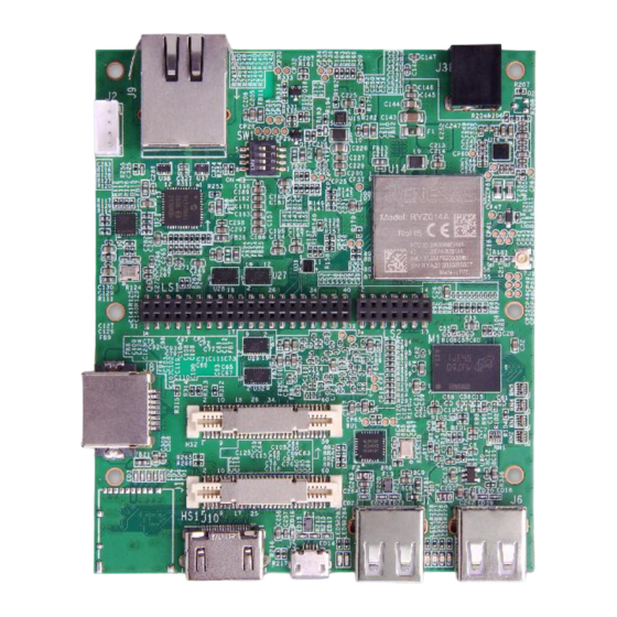
1.1 Board overview Top View Name Description USB2.0 HOST *1(USB Type-A) ① USB2.0 HOST *1(USB Type-A) ② USB-OTG *1(Micro-USB Type) ③ High-Speed Connector1 *1(MIPI-CSI/MIPI-DSI/USB/SD1) ④ High-Speed Connector2 *1(SPI/GPIO) ⑤ HDMI Connector *1(up to 1080P30) ⑥ TF Card solt ⑦ Gigabit RJ45 Connector1 ⑧... -
Page 6: What's In The Box
2. What’s in the Box The box contains one RS-G2L100&RS-V2L100 development board. Room 02-04, 10/F, Block A, Building 8, Shenzhen International Innovation Valley, Dashi Road, Nanshan District, Shenzhen, Guangdong, China... -
Page 7: Rs-G2L100&Rs-V2L100 Board Overview
3.RS-G2L100&RS-V2L100 BOARD OVERVIEW 3.1 System Block Diagram 3.2 Processor Renesas RZ/G2L&RZ/V2L chip is a general-purpose SOC with high performance and lower power consumption designed for industrial human machine interface devices and AIoT equipment. It adopts 22nm process technology, integrating 2-core arm architecture Cortex-A55 processor and Cortex-M33 core, 3D Graphics Acceleration Engine Mali-G31 and Video codec H.264. -
Page 8: Display Interface
3.5 Display Interface 3.5.1 HDMI The 96Boards specification calls for an HDMI port to be present on the board. The Renesas RZ/G2L&RZ/V2L doesn’t include a built-in HDMI interface. The Renesas RZ/G2L&RZ/V2L deploys the built-in MIPI-DSI 4 lanes interface as the source for the HDMI output. A peripheral DSI to HDMI Bridge (U25, Analog Devices ADV7533) performs this task and it supports a resolution from 480i to 1080p at 30Hz. -
Page 9: Audio
3.7 Audio Renesas RZ/G2L100&RZ/V2L100 supports the requirement of audio codec with MIC IN + Headphone Out 3.5 mm jack connector. Renesas RZ/G2L100&RZ/V2L100 supports Automotive Audio Bus interfaces in Master mode with 2 pin connector. 3.8 WiFi The 96Boards specification calls for WiFi module to be on the board. Renesas RZ/G2L100&RZ/V2L100 supports Wi-Fi (802.11 a/b/g/n, 2.4GHz) over DA16600MOD-AAE module. -
Page 10: Usb-Device Port
The RZ/G2L&RZ/V2L includes a single USBOTG channel. A USB1,routes this single USBOTG channel either to the MicroUSB connector (J5). There are total 3 USB ports on the RZ/G2L100&RZ/V2L100 Board. Two type A USB2.0 host ports at J6 and J7, one micro USB slave port at J5 and one USB host port available on the High Speed Expansion bus. -
Page 11: Uart{0/1
AGND AGND 4.1 UART{0/1} The 96Boards specifications calls for a 4-wire UART implementation, UART0 and an optimal second 2-wire UART, UART1 on the Low Speed Expansion Connector. The RZ/G2L100&RZ/V2L100 implements UART0 as a 4-wire UART that connects directly to the RZ/G2L&RZ/V2L SoC. These signals are driven at 1.8V. -
Page 12: 14-Pin Low Speed(Ls) Expansion Connector
The RZ/G2L100&RZ/V2L100 implements a PCM/I2S with 4 wires, LRCK,CK, SDOUT and SD IN, The I2S signals are connected directly to the RZ/G2L&RZ/V2L SoC. These signals are driven at 1.8V. 5 14-pin Low Speed(LS) expansion connector The following tables show the Low Speed Expansion Connector pin out: Pin No. -
Page 13: Mipi Dsi 2
HS1_SD1_DATA1 MIPI_CSI0_CLKN HS1_SD1_DATA2 HS1_SD1_DATA3 MIPI_CSI0_D0P HS1_SD1_CLK MIPI_CSI0_D0N HS1_SD1_CMD MIPI_CSI0_D1P P39_0_HS1_CLK0 MIPI_CSI0_D1N P39_1_HS1_CLK1 MIPI_CSI0_D2P MIPI_DSI2_CLKP MIPI_CSI0_D2N MIPI_DSI2_CLKN MIPI_CSI0_D3P MIPI_DSI2_D0P MIPI_CSI0_D3N MIPI_DSI2_D0N HS1_I2C2_SCL MIPI_DSI2_D1P HS1_I2C2_SDA MIPI_DSI2_D1N HS1_I2C3_SCL HS1_I2C3_SDA MIPI_DSI2_D2P MIPI_DSI2_D2N MIPI_DSI2_D3P MIPI_DSI2_D3N USB3_HUB_DP USB3_HUB_DN 6.1 MIPI DSI 2 Room 02-04, 10/F, Block A, Building 8, Shenzhen International Innovation Valley, Dashi Road, Nanshan District, Shenzhen, Guangdong, China... -
Page 14: Mipi Csi 0
The 96Boards specification calls for a MIPI-DSI to be present on the High Speed Expansion Connector. A minimum of one lane is required and up to four lanes can be accommodated on the connector. The RZ/G2L100&RZ/V2L100 implementation supports a full four lane MIPI-DSI interface that is routed to the High Speed Expansion Connector. -
Page 15: Spi 2
HS2_SPI2_CLK HS2_SPI2_CS HS2_SPI2_MOSI HS2_SPI2_MISO HS2_GPIO_V HS2_GPIO_W HS2_GPIO_X HS2_GPIO_Y 7.1 SPI 2 The 96Boards specification calls for one SPI bus master to be provided on the Low Speed Expansion Connector. The RZ/G2L100&RZ/V2L100 implements a full SPI master with 4 wires, CLK, CS, MOSI and MISO all connect directly to the RZ/G2L&RZ/V2L SoC. -
Page 16: Power Management
GPIO Y - Connects to P47_1 of RZ/G2L&RZ/V2L SoC. It is a 1.8V signal. 8 Power management RS-G2L100&RS-V2L100 supports 12VDC(+8V to 18V @60W) for the input supply to power up processor and all its peripherals. The processor and peripherals requires different voltage supplies and current for their normal functionality. The power supply section is designed to generate all required voltage rails with respective current requirements. -
Page 17: Boot Configuration
The four user LEDs are surface mount Green LEDs, 0603 size, located next to the two USB type A connector and labeled ‘USER LEDS 3 2 1 0’. Bluetooth status The BT LED on the Renesas RZ/G2L&RZ/V2L is located next to the USBOTG connector, this LED reflects the status of the Bluetooth device. -
Page 18: Mechanical Specification
11 Mechanical specification Board dimensions Room 02-04, 10/F, Block A, Building 8, Shenzhen International Innovation Valley, Dashi Road, Nanshan District, Shenzhen, Guangdong, China...
Need help?
Do you have a question about the RS-G2L100&RS-V2L100 and is the answer not in the manual?
Questions and answers