Table of Contents
Advertisement
Quick Links
www.ti.com
EVM User's Guide: PCMX140Q1EVM-PDK
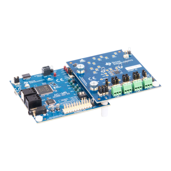
PCMx140Q1EVM-PDK Evaluation Module
Description
The ADCx140EVM-PDK is an evaluation module
(EVM) that allows the user to test the
capabilities of the PCMx140-Q1 family of devices,
which is a quad-channel, high-performance audio
analog-to-digital converter (ADC). The PCMx140-
Q1 is intended for voice-activated systems,
professional microphones, audio conferencing,
portable computing, communication, entertainment,
and automotive applications. PCMx140Q1EVM-PDK
is paired with the AC-MB (included in the kit), a
flexible motherboard that provides power, control, and
digital audio data to the EVM.
Get Started
1. Order the EVM from the
product page.
2. Download the latest PCMx140-Q1 data sheet.
3. Request access and download PPC3 GUI and the
associated PCMx140Q1EVM-PDK app from the
PCMx140Q1EVM-PDK
SBAU443 – NOVEMBER 2023
Submit Document Feedback
PCMx140Q1EVM-PDK
product page.
Copyright © 2023 Texas Instruments Incorporated
Features
•
Complete performance demonstration kit (PDK) for
PCMx140-Q1
•
High-performance audio ADC: 106, 108, or 113-dB
dynamic range
•
Dynamic Range Enhancer (DRE) improves
dynamic range performance in far field
applications (PCM5140-Q1, and PCM6140-Q1
only)
•
Rail-to-Rail CMRR performance mode (PCM6140-
Q1 only)
•
Onboard microphone provided for voice-recording
testing
•
Direct access to digital audio signals and control
interface for simple end-system integration
•
USB connection to PC provides power, control,
and streaming audio data for easy evaluation
•
Easy evaluation and demonstration via
PurePath
™
Console software platform
(PUREPATHCONSOLE)
Applications
•
Microphone array systems
•
Voice-activated digital assistants
•
Teleconferencing systems
•
Security and surveillance systems
PCMx140Q1EVM-PDK Evaluation Module
Description
1
Advertisement
Table of Contents

Related Manuals for Texas Instruments PCMx140Q1EVM-PDK


Summary of Contents for Texas Instruments PCMx140Q1EVM-PDK
- Page 1 Easy evaluation and demonstration via 2. Download the latest PCMx140-Q1 data sheet. PurePath ™ Console software platform 3. Request access and download PPC3 GUI and the (PUREPATHCONSOLE) associated PCMx140Q1EVM-PDK app from the Applications PCMx140Q1EVM-PDK product page. • Microphone array systems •...
-
Page 2: Kit Contents
1 Evaluation Module Overview 1.1 Introduction This user's guide describes the function and use of the PCMx140Q1EVM-PDK. This document includes the hardware configuration instructions, a quick-start guide, jumper and connector descriptions, software description, schematics, and printed circuit board (PCB) layout that demonstrate TI's recommended practices for these devices. -
Page 3: Hardware Overview
The daughterboard contains the PCMx140-Q1 device and the input connections. A detailed functional overview of the PCMx140Q1EVM system is described in Section 2.1. SBAU443 – NOVEMBER 2023 PCMx140Q1EVM-PDK Evaluation Module Submit Document Feedback Copyright © 2023 Texas Instruments Incorporated... - Page 4 The AC-MB acts as the controller for the audio serial interface, with three different modes of operation (see Figure 2-3): USB, optical or analog, or external ASI. PCMx140Q1EVM-PDK Evaluation Module SBAU443 – NOVEMBER 2023 Submit Document Feedback Copyright © 2023 Texas Instruments Incorporated...
- Page 5 The AC-MB is detected by the OS as an audio device with the name TI USB Audio UAC2.0. Figure 2-3 shows the AC-MB audio setting for the USB mode of operation. Figure 2-3. AC-MB USB Audio Setting SBAU443 – NOVEMBER 2023 PCMx140Q1EVM-PDK Evaluation Module Submit Document Feedback Copyright © 2023 Texas Instruments Incorporated...
- Page 6 This feature can be useful when a digital input DAC is connected to the AC-MB, providing an analog input for quick evaluation. In Auxiliary Analog Audio mode the audio serial interface format is fixed to a 24-bit, 48-kHz, I mode. PCMx140Q1EVM-PDK Evaluation Module SBAU443 – NOVEMBER 2023 Submit Document Feedback Copyright © 2023 Texas Instruments Incorporated...
- Page 7 USB interface and PCM9211 are isolated with this setting. Figure 2-5 shows the AC-MB audio setting for the external mode of operation. Figure 2-5. AC-MB External Audio Setting SBAU443 – NOVEMBER 2023 PCMx140Q1EVM-PDK Evaluation Module Submit Document Feedback Copyright © 2023 Texas Instruments Incorporated...
- Page 8 Host Processor / Audio Analyzer Figure 2-6. AC-MB Connection with External Audio Serial Interface PCMx140Q1EVM-PDK Evaluation Module SBAU443 – NOVEMBER 2023 Submit Document Feedback Copyright © 2023 Texas Instruments Incorporated...
- Page 9 POWER LED (D3) turns ON. The USB READY LED indicates that a successful USB communication is established between the AC-MB and the host computer. SBAU443 – NOVEMBER 2023 PCMx140Q1EVM-PDK Evaluation Module Submit Document Feedback Copyright © 2023 Texas Instruments Incorporated...
- Page 10 7bit I2C addresses that correspond to each combination of J18 and J19. Table 2-1. I2C Address Selection Address 0x4C 0x4D 0x4E 0x4F PCMx140Q1EVM-PDK Evaluation Module SBAU443 – NOVEMBER 2023 Submit Document Feedback Copyright © 2023 Texas Instruments Incorporated...
-
Page 11: Line Inputs
J2 (IN1), J3 (IN2), J4 (IN3), and J5 (IN4). The input accepted in this mode is a differential, 2-VRMS, full-scale audio signal. If a single-ended source is used, the 1-VRMS signal is supported. Figure 2-9. PCMx140Q1EVM Connection for Line Input Application SBAU443 – NOVEMBER 2023 PCMx140Q1EVM-PDK Evaluation Module Submit Document Feedback Copyright © 2023 Texas Instruments Incorporated... - Page 12 J14 must be shorted. There must not be any connections to J1 during onboard microphone use to preserve the performance of the microphone. Figure 2-10. PCMx140Q1EVM Connection for the Onboard Microphone Test PCMx140Q1EVM-PDK Evaluation Module SBAU443 – NOVEMBER 2023 Submit Document Feedback Copyright © 2023 Texas Instruments Incorporated...
- Page 13 3.1.1 PurePath Console 3 Installation The PCMx140Q1EVM-PDK GUI is an application that installs into the PPC3 framework. PPC3 must be installed prior to downloading the PCMx140Q1EVM-PDK GUI. To download the PPC3, visit www.ti.com/tool/...
-
Page 14: Software Setup
The PCMx140Q1 GUI is designed to work with up to four devices at any time. As shown in Figure 3-3, choose the 1 device radial button and click New. Figure 3-3. Initial GUI Configuration PCMx140Q1EVM-PDK Evaluation Module SBAU443 – NOVEMBER 2023 Submit Document Feedback Copyright © 2023 Texas Instruments Incorporated... -
Page 15: Quick Start
The PCMx140Q1 does not provide a digital audio output in standby mode. Figure 3-8 shows how to change the mode from standby to active. Figure 3-8. Standby to Active Mode SBAU443 – NOVEMBER 2023 PCMx140Q1EVM-PDK Evaluation Module Submit Document Feedback Copyright © 2023 Texas Instruments Incorporated... - Page 16 In the ASI format configuration pane (shown in Figure 3-11), change the protocol format to I S, and the word length to 16 bits. Figure 3-11. ASI Format Configuration PCMx140Q1EVM-PDK Evaluation Module SBAU443 – NOVEMBER 2023 Submit Document Feedback Copyright © 2023 Texas Instruments Incorporated...
- Page 17 S mode and the BCLK and FSYNC ratio is fixed at 64. The EVM is now ready for use with the audio recording program of your choice. SBAU443 – NOVEMBER 2023 PCMx140Q1EVM-PDK Evaluation Module Submit Document Feedback Copyright © 2023 Texas Instruments Incorporated...
- Page 18 PPC3 window and select Open. Navigate to the location of the saved .ppc3 file, and click Open. Figure 3-14. Saving a Configuration in PPC3 PCMx140Q1EVM-PDK Evaluation Module SBAU443 – NOVEMBER 2023 Submit Document Feedback Copyright © 2023 Texas Instruments Incorporated...
- Page 19 'SampleRate', 48000, … 'NumChannels', 8 ,… 'BitDepth', '32-bit float',… 'OutputDataType','double'); elseif ispc % windows driver devoiceReader = audioDeviceReader( 'Driver','ASIO', 'Device', 'Texas Instruments USB Audio ...',… 'SampleRate', 48000, … 'NumChannels', 8 ,… 'BitDepth', '32-bit float',… 'OutputDataType','double’); setup(deviceReader);% Setup the device reader % Play out a file through PC and capture in the EVM info = audioinfo( infile_name );% Read audiophile infile_name...
- Page 20 Hardware Design Files www.ti.com 4 Hardware Design Files 4.1 PCMx140Q1EVM-PDK Schematic and Bill of Materials This section provides the schematics and bill of materials (BOM) for the PCMx140Q1EVM-PDK. 4.1.1 PCMx140Q1EVM-PDK Schematic Figure 4-1 shows the schematics for the PCMx140Q1EVM-PDK. MICBIAS...
-
Page 21: Pcb Layouts
Hardware Design Files 4.1.2 PCB Layouts Figure 4-2. Top Layer Figure 4-3. Ground Layer SBAU443 – NOVEMBER 2023 PCMx140Q1EVM-PDK Evaluation Module Submit Document Feedback Copyright © 2023 Texas Instruments Incorporated... - Page 22 Hardware Design Files www.ti.com Figure 4-4. Power Layer Figure 4-5. Bottom Layer PCMx140Q1EVM-PDK Evaluation Module SBAU443 – NOVEMBER 2023 Submit Document Feedback Copyright © 2023 Texas Instruments Incorporated...
- Page 23 Hardware Design Files 4.1.3 PCMx140Q1EVM-PDK Bill of Materials Table 4-1 lists the BOM for the PCMx140Q1EVM-PDK. Table 4-1. PCMx140Q1EVM-PDK Bill of Materials Designator Value Description Package Reference Part Number Manufacturer C1, C3, C7, C9, C11, C13, 0.1uF CAP, CERM, 0.1 uF, 16 V, +/- 10%, X7R, 0402 0402 8.85012E+11...
- Page 24 Hardware Design Files www.ti.com Table 4-1. PCMx140Q1EVM-PDK Bill of Materials (continued) Designator Value Description Package Reference Part Number Manufacturer SH1, SH2, SH3, SH4, SH5, SH6, SH7, SH8, SH9, Shunt, 100mil, Gold plated, Black Shunt SNT-100-BK-G Samtec SH10, SH11, SH12, SH13...
- Page 25 EVM-SPI-MOSI 0.1uF 0.1uF 0.1uF 0.1uF 0.1uF 0.1uF 0.1uF 0.1uF EVM-SPI-SS0 EVM-SPI-SS1 I²C Power Control Interface Translation Test Points EVM Connector Figure 4-6. AC-MB Schematics SBAU443 – NOVEMBER 2023 PCMx140Q1EVM-PDK Evaluation Module Submit Document Feedback Copyright © 2023 Texas Instruments Incorporated...
- Page 26 Hardware Design Files www.ti.com 4.2.2 PCB Layouts Figure 4-7. Top Layer Figure 4-8. Ground Layer PCMx140Q1EVM-PDK Evaluation Module SBAU443 – NOVEMBER 2023 Submit Document Feedback Copyright © 2023 Texas Instruments Incorporated...
- Page 27 Hardware Design Files Figure 4-9. Power Layer Figure 4-10. Bottom Layer SBAU443 – NOVEMBER 2023 PCMx140Q1EVM-PDK Evaluation Module Submit Document Feedback Copyright © 2023 Texas Instruments Incorporated...
- Page 28 Thumb Nut, M3 x 0.5 Thread, 8 mm Head Dia 96115A420 McMaster Carr H7, H8, H9, H10 Standoff, Hex, Male/Female, 4-40, Nylon, 1/2" Standoff, Hex, Male/ 4802 Keystone Female, 4-40, Nylon, 1/2" PCMx140Q1EVM-PDK Evaluation Module SBAU443 – NOVEMBER 2023 Submit Document Feedback Copyright © 2023 Texas Instruments Incorporated...
- Page 29 RES, 51.0 k, 1%, 0.05 W, 0201 0201 RC0201FR-0751KL Yageo America 40.2k RES, 40.2 k, 1%, 0.063 W, AEC-Q200 Grade 0, 0402 0402 CRCW040240K2FKED Vishay-Dale SBAU443 – NOVEMBER 2023 PCMx140Q1EVM-PDK Evaluation Module Submit Document Feedback Copyright © 2023 Texas Instruments Incorporated...
- Page 30 4-Bit Dual-Supply Bus Transceiver With Configurable RSV0016A SN74AVC4T774RSVR Texas Instruments U21, U22 Voltage-Level Shifting and 3-State Outputs, RSV0016A (UQFN-16) Photolink- Fiber Optic Receiver, TH 13.5x10x9.7mm PLR135/T10 Everlight PCMx140Q1EVM-PDK Evaluation Module SBAU443 – NOVEMBER 2023 Submit Document Feedback Copyright © 2023 Texas Instruments Incorporated...
- Page 31 Test Point, Miniature, Red, TH Red Miniature Testpoint 5000 Keystone TP3, TP4, TP5, TP6, Test Point, Miniature, Green, TH Green Miniature Testpoint 5116 Keystone TP11, TP12, TP13 SBAU443 – NOVEMBER 2023 PCMx140Q1EVM-PDK Evaluation Module Submit Document Feedback Copyright © 2023 Texas Instruments Incorporated...
-
Page 32: Additional Information
Additional Information www.ti.com 5 Additional Information 5.1 Trademarks PurePath ™ is a trademark of Texas Instruments. Audio Toolbox ™ is a trademark of MathWorks. All trademarks are the property of their respective owners. 6 Related Documentation Table 6-1. PCMx140-Q1 Family and Related Data Sheet... - Page 33 STANDARD TERMS FOR EVALUATION MODULES Delivery: TI delivers TI evaluation boards, kits, or modules, including any accompanying demonstration software, components, and/or documentation which may be provided together or separately (collectively, an “EVM” or “EVMs”) to the User (“User”) in accordance with the terms set forth herein.
- Page 34 www.ti.com Regulatory Notices: 3.1 United States 3.1.1 Notice applicable to EVMs not FCC-Approved: FCC NOTICE: This kit is designed to allow product developers to evaluate electronic components, circuitry, or software associated with the kit to determine whether to incorporate such items in a finished product and software developers to write software applications for use with the end product.
- Page 35 www.ti.com Concernant les EVMs avec antennes détachables Conformément à la réglementation d'Industrie Canada, le présent émetteur radio peut fonctionner avec une antenne d'un type et d'un gain maximal (ou inférieur) approuvé pour l'émetteur par Industrie Canada. Dans le but de réduire les risques de brouillage radioélectrique à...
- Page 36 www.ti.com EVM Use Restrictions and Warnings: 4.1 EVMS ARE NOT FOR USE IN FUNCTIONAL SAFETY AND/OR SAFETY CRITICAL EVALUATIONS, INCLUDING BUT NOT LIMITED TO EVALUATIONS OF LIFE SUPPORT APPLICATIONS. 4.2 User must read and apply the user guide and other available documentation provided by TI regarding the EVM prior to handling or using the EVM, including without limitation any warning or restriction notices.
- Page 37 Notwithstanding the foregoing, any judgment may be enforced in any United States or foreign court, and TI may seek injunctive relief in any United States or foreign court. Mailing Address: Texas Instruments, Post Office Box 655303, Dallas, Texas 75265 Copyright © 2023, Texas Instruments Incorporated...
-
Page 38: Important Notice
TI products. TI’s provision of these resources does not expand or otherwise alter TI’s applicable warranties or warranty disclaimers for TI products. TI objects to and rejects any additional or different terms you may have proposed. IMPORTANT NOTICE Mailing Address: Texas Instruments, Post Office Box 655303, Dallas, Texas 75265 Copyright © 2023, Texas Instruments Incorporated...
Need help?
Do you have a question about the PCMx140Q1EVM-PDK and is the answer not in the manual?
Questions and answers