Table of Contents
Advertisement
Quick Links
www.ti.com
User's Guide
PCM182xEVM/PCM182xQ1EVM EVM User's Guide
This user's guide describes the function and use of the PCM1820EVM /PCM1821EVM/ PCM1822EVM /
PCM1820Q1EVM/PCM1821Q1EVM/PCM1822Q1EVM evaluation modules. This document includes the
hardware configuration instructions, a quick-start guide, jumper and connector descriptions, schematics, and
printed-circuit board (PCB) layout that demonstrate TI's recommended practices for these devices .
SBAU363A – FEBRUARY 2021 – REVISED MARCH 2022
Submit Document Feedback
ABSTRACT
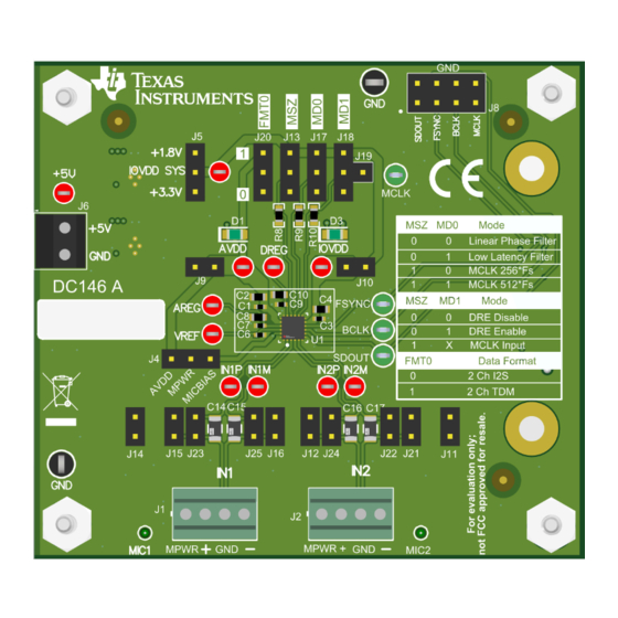
Figure 1-1. EVM BOARD
Copyright © 2022 Texas Instruments Incorporated
PCM182xEVM/PCM182xQ1EVM EVM User's Guide
1
Advertisement
Table of Contents

Related Manuals for Texas Instruments PCM182xEVM


Summary of Contents for Texas Instruments PCM182xEVM
-
Page 1: Figure 1-1. Evm Board
(PCB) layout that demonstrate TI's recommended practices for these devices . Figure 1-1. EVM BOARD SBAU363A – FEBRUARY 2021 – REVISED MARCH 2022 PCM182xEVM/PCM182xQ1EVM EVM User's Guide Submit Document Feedback Copyright © 2022 Texas Instruments Incorporated... -
Page 2: Table Of Contents
Figure 6-1. Schematic................................12 Trademarks Burr-Brown ™ is a trademark of Texas Instruments. All trademarks are the property of their respective owners. PCM182xEVM/PCM182xQ1EVM EVM User's Guide SBAU363A – FEBRUARY 2021 – REVISED MARCH 2022 Submit Document Feedback Copyright © 2022 Texas Instruments Incorporated... -
Page 3: Introduction
I2S or TDM format. 2 Power Supply The PCM182xEVM/PCM182xQ1EVM can be powered with a single 5-V power supply connected to J6. Onboard low dropout regulators convert the 5-V supply to the 3.3-V and 1.8-V rails used by the ADC. The analog supply, AVDD, is fixed at 3.3 V. -
Page 4: Hardware Configuration
J19 to the center pin of J18 will route the MCLK signal provided on J8 to the MD1 pin on the ADC to allow for easy interfacing with audio measurement equipment. Table 3-1. PCM182xEVM /PCM182xQ1EVM Headers and Jumpers Designator... - Page 5 The DRE is enabled with DRE_LVL = –36 dB and DRE_MAXGAIN = 24 dB MCLK MCLK input in master mode Table 3-4. PCM182xEVM /PCM182xQ1EVM Audio Output Format Audio Output Data Format FMT0 Audio Serial Interface Format 2-channel output with inter IC sound (I2S) mode...
-
Page 6: Pcm182Xevm /Pcm182Xq1Evm Inputs
J4, J11,J12, J14, J15, J16, and J21. If the onboard mics are used, leave the J1 and J2 headers unconnected to preserve the microphone performance. PCM182xEVM/PCM182xQ1EVM EVM User's Guide SBAU363A – FEBRUARY 2021 – REVISED MARCH 2022 Submit Document Feedback Copyright © 2022 Texas Instruments Incorporated... -
Page 7: Line Inputs
0 ohms. PCM1822/PCM1822-Q1 accepts , 1 VRMS, single ended/differential full-scale audio signal Figure 4-3. PCM182x/ PCM182x-Q1 Line Inputs SBAU363A – FEBRUARY 2021 – REVISED MARCH 2022 PCM182xEVM/PCM182xQ1EVM EVM User's Guide Submit Document Feedback Copyright © 2022 Texas Instruments Incorporated... -
Page 8: Layer Plots
Layer Plots www.ti.com 5 Layer Plots Figure 5-1. Top Layer PCM182xEVM/PCM182xQ1EVM EVM User's Guide SBAU363A – FEBRUARY 2021 – REVISED MARCH 2022 Submit Document Feedback Copyright © 2022 Texas Instruments Incorporated... -
Page 9: Figure 5-2. Power Plane 1
Layer Plots Figure 5-2. Power Plane 1 SBAU363A – FEBRUARY 2021 – REVISED MARCH 2022 PCM182xEVM/PCM182xQ1EVM EVM User's Guide Submit Document Feedback Copyright © 2022 Texas Instruments Incorporated... -
Page 10: Figure 5-3. Power Plane 2
Layer Plots www.ti.com Figure 5-3. Power Plane 2 PCM182xEVM/PCM182xQ1EVM EVM User's Guide SBAU363A – FEBRUARY 2021 – REVISED MARCH 2022 Submit Document Feedback Copyright © 2022 Texas Instruments Incorporated... -
Page 11: Figure 5-4. Bottom Layer
Layer Plots Figure 5-4. Bottom Layer SBAU363A – FEBRUARY 2021 – REVISED MARCH 2022 PCM182xEVM/PCM182xQ1EVM EVM User's Guide Submit Document Feedback Copyright © 2022 Texas Instruments Incorporated... -
Page 12: Schematics
Schematics www.ti.com 6 Schematics Figure 6-1 illustrates the EVM schematic. Figure 6-1. Schematic PCM182xEVM/PCM182xQ1EVM EVM User's Guide SBAU363A – FEBRUARY 2021 – REVISED MARCH 2022 Submit Document Feedback Copyright © 2022 Texas Instruments Incorporated... -
Page 13: Bill Of Materials
PCB Label 0.650 x THT-14-423-10 Brady Printable Labels, 0.650" 0.200 inch W x 0.200" H - 10,000 per roll SBAU363A – FEBRUARY 2021 – REVISED MARCH 2022 PCM182xEVM/PCM182xQ1EVM EVM User's Guide Submit Document Feedback Copyright © 2022 Texas Instruments Incorporated... - Page 14 FID5, FID6 R3, R5 RES, 0, 5%, 0.1 W, 0603 0603 CRCW06030000 Vishay-Dale Z0EA PCM182xEVM/PCM182xQ1EVM EVM User's Guide SBAU363A – FEBRUARY 2021 – REVISED MARCH 2022 Submit Document Feedback Copyright © 2022 Texas Instruments Incorporated...
-
Page 15: Revision History
Changes from Revision * (February 2021) to Revision A (March 2022) Page • Updated User's Guide to include references to PCM1820-Q1, PCM1821-Q1 and PCM1822-Q1..... SBAU363A – FEBRUARY 2021 – REVISED MARCH 2022 PCM182xEVM/PCM182xQ1EVM EVM User's Guide Submit Document Feedback Copyright © 2022 Texas Instruments Incorporated... - Page 16 TI products. TI’s provision of these resources does not expand or otherwise alter TI’s applicable warranties or warranty disclaimers for TI products. TI objects to and rejects any additional or different terms you may have proposed. IMPORTANT NOTICE Mailing Address: Texas Instruments, Post Office Box 655303, Dallas, Texas 75265 Copyright © 2022, Texas Instruments Incorporated...
Need help?
Do you have a question about the PCM182xEVM and is the answer not in the manual?
Questions and answers