Advertisement
Quick Links
This user's guide describes the function and use of the PCM6xx0Q1EVM-PDK. This document includes
the hardware configuration instructions, a quick-start guide, jumper and connector descriptions, software
description, schematics, and printed circuit board (PCB) layout that demonstrate TI's recommended
practices for these devices.
...................................................................................................................
1
2
2.1
2.2
PCM6xx0Q1EVM-PDK Hardware Settings
3
3.1
PurePath Console 3 Installation
3.2
PCM6xx0Q1EVM GUI Installation and Setup
4
Software Overview
4.1
4.2
4.3
..................................................................................................................
5
SBAU341B - January 2020 - Revised June 2020
Submit Documentation Feedback
PCM6xx0Q1EVM-PDK Evaluation Module
layer
Contents
..........................................................................................................
.....................................................................................................
.........................................................................................................
.................................................................................
.........................................................................................................
................................................................................................
...........................................................................................
.......................................................................................................
Copyright © 2020, Texas Instruments Incorporated
SBAU341B - January 2020 - Revised June 2020
......................................................................
.................................................................
PCM6xx0Q1EVM-PDK Evaluation Module
User's Guide
3
3
3
7
17
17
18
20
20
29
30
31
1
Advertisement

Subscribe to Our Youtube Channel
Related Manuals for Texas Instruments PCM6 0Q1EVM-PDK Series


Summary of Contents for Texas Instruments PCM6 0Q1EVM-PDK Series
-
Page 1: Table Of Contents
PCM6xx0Q1EVM GUI Installation and Setup ......................Software Overview ....................Configuration View ................... End System Integration ....................... Register Map ........................Quick Start SBAU341B – January 2020 – Revised June 2020 PCM6xx0Q1EVM-PDK Evaluation Module Submit Documentation Feedback Copyright © 2020, Texas Instruments Incorporated... - Page 2 PCM6360Q1EVM Bill of Materials ....................AC-MB Bill of Materials Trademarks PurePath is a trademark of Texas Instruments. Audio Precision is a trademark of Audio Precision, Inc. Audio Toolbox is a trademark of MathWorks. All other trademarks are the property of their respective owners.
-
Page 3: Introduction
The AC-MB acts as the master for the audio serial interface, with three different modes of operation (see Figure 2): USB, optical or analog, or external ASI. SBAU341B – January 2020 – Revised June 2020 PCM6xx0Q1EVM-PDK Evaluation Module Submit Documentation Feedback Copyright © 2020, Texas Instruments Incorporated... - Page 4 (DAC) is connected to the AC-MB, providing an analog input for quick evaluation. In auxiliary analog audio mode, the audio serial interface format is fixed to a 24-bit, 48-kHz, I S mode. PCM6xx0Q1EVM-PDK Evaluation Module SBAU341B – January 2020 – Revised June 2020 Submit Documentation Feedback Copyright © 2020, Texas Instruments Incorporated...
- Page 5 Host Processor / Audio Analyzer Figure 5. AC-MB Connection With External Audio Serial Interface SBAU341B – January 2020 – Revised June 2020 PCM6xx0Q1EVM-PDK Evaluation Module Submit Documentation Feedback Copyright © 2020, Texas Instruments Incorporated...
- Page 6 ON. The USB READY LED indicates that a successful USB communication is established between the AC-MB and the host computer. PCM6xx0Q1EVM-PDK Evaluation Module SBAU341B – January 2020 – Revised June 2020 Submit Documentation Feedback Copyright © 2020, Texas Instruments Incorporated...
- Page 7 IN3M IN4P IN4M IN5P IN5M IN6P IN6M MICBIAS MICBIAS MICBIAS MICBIAS MICBIAS Figure 8. PCM6xx0Q1EVM Input Architecture for Channels 3-6 SBAU341B – January 2020 – Revised June 2020 PCM6xx0Q1EVM-PDK Evaluation Module Submit Documentation Feedback Copyright © 2020, Texas Instruments Incorporated...
- Page 8 J25 and J26 installed; J27 optional (MICBIAS); R40 and (normal mode) Single-ended, DC-coupled R41 removed (high swing mode) External electrect microphone PCM6xx0Q1EVM-PDK Evaluation Module SBAU341B – January 2020 – Revised June 2020 Submit Documentation Feedback Copyright © 2020, Texas Instruments Incorporated...
- Page 9 The input bias resistors have been selected to support line inputs in high swing mode. Figure 9. PCM6xx0Q1EVM Connection for Line Input Application SBAU341B – January 2020 – Revised June 2020 PCM6xx0Q1EVM-PDK Evaluation Module Submit Documentation Feedback Copyright © 2020, Texas Instruments Incorporated...
- Page 10 10 V 4.7 kΩ 150 kΩ Differential 110 kΩ 62 kΩ 4.3 kΩ 47 kΩ Single-ended 30 kΩ 15 kΩ PCM6xx0Q1EVM-PDK Evaluation Module SBAU341B – January 2020 – Revised June 2020 Submit Documentation Feedback Copyright © 2020, Texas Instruments Incorporated...
- Page 11 R4 and R2 be changed to optimize microphone performance. External Electret Microphone Figure 10. PCM6xx0Q1EVM Connection for the Onboard Microphone Test SBAU341B – January 2020 – Revised June 2020 PCM6xx0Q1EVM-PDK Evaluation Module Submit Documentation Feedback Copyright © 2020, Texas Instruments Incorporated...
- Page 12 Short to MICBIAS To J1.3 (IN1M) To J1.1 To J1.1 (IN1P) (IN1P) Figure 12. Short to MICBIAS Diagnostic Test Setup PCM6xx0Q1EVM-PDK Evaluation Module SBAU341B – January 2020 – Revised June 2020 Submit Documentation Feedback Copyright © 2020, Texas Instruments Incorporated...
- Page 13 Figure 13. Short to VBAT Diagnostic Test Setup 2.2.3.3 Shorted Input Pins Setup Shorted input testing (Figure 14) can be performed for differential inputs only. SBAU341B – January 2020 – Revised June 2020 PCM6xx0Q1EVM-PDK Evaluation Module Submit Documentation Feedback Copyright © 2020, Texas Instruments Incorporated...
- Page 14 Differential Input Test setup To J1.3 (IN1M) To J1.1 To J1.1 (IN1P) (IN1P) Figure 15. Short to Ground Diagnostic Test Setup PCM6xx0Q1EVM-PDK Evaluation Module SBAU341B – January 2020 – Revised June 2020 Submit Documentation Feedback Copyright © 2020, Texas Instruments Incorporated...
- Page 15 Other GPIO functionality can also be supported by using the GPIO1 header (J28). This approach requires the removal of both R21 and R22. In this configuration the GPIO1 can be connected using J28. SBAU341B – January 2020 – Revised June 2020 PCM6xx0Q1EVM-PDK Evaluation Module Submit Documentation Feedback Copyright © 2020, Texas Instruments Incorporated...
- Page 16 R12, R14 R11, R13 1001 001 R11, R14 R12, R13 1001 010 R12, R13 R11, R14 1001 011 R11, R13 R12,R14 PCM6xx0Q1EVM-PDK Evaluation Module SBAU341B – January 2020 – Revised June 2020 Submit Documentation Feedback Copyright © 2020, Texas Instruments Incorporated...
-
Page 17: Software Overview
PPC3 installation. Figure 18. PurePath Console 3 Installation Open the PPC3 installer and follow the instructions in the setup wizard. SBAU341B – January 2020 – Revised June 2020 PCM6xx0Q1EVM-PDK Evaluation Module Submit Documentation Feedback Copyright © 2020, Texas Instruments Incorporated... - Page 18 Access to the PCM6260Q1EVM-SW can be requested from the www.ti.com/tool/PCM6260Q1EVM. 3.2.2 USB Audio Setup When using the USB audio interface, the Texas Instruments USB audio device control panel, shown in Figure 19, opens with the input setting configured for 8 channel, 32 bits. For USB audio, 32-bit mode must be used on the EVM as well.
- Page 19 Figure 21. Initial GUI Configuration As shown in Figure 22, the GUI opens to the Audio Config tab. Figure 22. Audio Config Tab SBAU341B – January 2020 – Revised June 2020 PCM6xx0Q1EVM-PDK Evaluation Module Submit Documentation Feedback Copyright © 2020, Texas Instruments Incorporated...
-
Page 20: Configuration View
PCM6xx0Q1EVM. This view features tabbed navigation for each of the device configuration panels. These different tabs are detailed in this section. Figure 24. Configuration View PCM6xx0Q1EVM-PDK Evaluation Module SBAU341B – January 2020 – Revised June 2020 Submit Documentation Feedback Copyright © 2020, Texas Instruments Incorporated... - Page 21 The audio config tab (Figure 25) contains the controls for the analog inputs and the associated input channels. Figure 25. Audio Config Tab SBAU341B – January 2020 – Revised June 2020 PCM6xx0Q1EVM-PDK Evaluation Module Submit Documentation Feedback Copyright © 2020, Texas Instruments Incorporated...
- Page 22 When a mask is enabled any masked faults still display, however these masks do not trigger an interrupt. Figure 26. Diagnostics Tab PCM6xx0Q1EVM-PDK Evaluation Module SBAU341B – January 2020 – Revised June 2020 Submit Documentation Feedback Copyright © 2020, Texas Instruments Incorporated...
- Page 23 Phase-Locked Loop (PLL) and Clock Generation section in the TLV320ADCx140 family of devices details on supported formats. Figure 27. Audio Serial Bus Tab SBAU341B – January 2020 – Revised June 2020 PCM6xx0Q1EVM-PDK Evaluation Module Submit Documentation Feedback Copyright © 2020, Texas Instruments Incorporated...
- Page 24 29), change the protocol format to I S, and the word length to 16 bits. Figure 29. ASI Format Configuration PCM6xx0Q1EVM-PDK Evaluation Module SBAU341B – January 2020 – Revised June 2020 Submit Documentation Feedback Copyright © 2020, Texas Instruments Incorporated...
- Page 25 BCLK and FSYNC ratio is fixed at 64. The EVM is now ready for use with the audio recording program of your choice. SBAU341B – January 2020 – Revised June 2020 PCM6xx0Q1EVM-PDK Evaluation Module Submit Documentation Feedback Copyright © 2020, Texas Instruments Incorporated...
- Page 26 GPIO1 is always chip interrupt (IRQ). If alternate settings are required, see to ensure the proper hardware setup is followed. Figure 32. GPIO and Interrupts Tab PCM6xx0Q1EVM-PDK Evaluation Module SBAU341B – January 2020 – Revised June 2020 Submit Documentation Feedback Copyright © 2020, Texas Instruments Incorporated...
- Page 27 PCM6xx0 Programmable Biquad Filter Configuration and Applications application report. Figure 33. Programmable Biquads Tab SBAU341B – January 2020 – Revised June 2020 PCM6xx0Q1EVM-PDK Evaluation Module Submit Documentation Feedback Copyright © 2020, Texas Instruments Incorporated...
- Page 28 AGC enabled in the audio config tab for the AGC configuration to become active. These software controls are greyed out and inactive while the device is in active mode. Figure 34. AGC Tab PCM6xx0Q1EVM-PDK Evaluation Module SBAU341B – January 2020 – Revised June 2020 Submit Documentation Feedback Copyright © 2020, Texas Instruments Incorporated...
-
Page 29: End System Integration
.cfg file. The header file can be used for quick integration with a simple microcontroller. Figure 35. End System Integration View SBAU341B – January 2020 – Revised June 2020 PCM6xx0Q1EVM-PDK Evaluation Module Submit Documentation Feedback Copyright © 2020, Texas Instruments Incorporated... -
Page 30: Register Map
The register map view (Figure 36) provides a view of the first two pages of the register map. Figure 36. Register Map View PCM6xx0Q1EVM-PDK Evaluation Module SBAU341B – January 2020 – Revised June 2020 Submit Documentation Feedback Copyright © 2020, Texas Instruments Incorporated... -
Page 31: Quick Start
Figure 39 shows how to change the mode from standby to active. Figure 39. Inactive to Active Mode SBAU341B – January 2020 – Revised June 2020 PCM6xx0Q1EVM-PDK Evaluation Module Submit Documentation Feedback Copyright © 2020, Texas Instruments Incorporated... - Page 32 Figure 40. Disabled Controls in Active Mode Audio can now be captured on your PC using the audio program of your choice. PCM6xx0Q1EVM-PDK Evaluation Module SBAU341B – January 2020 – Revised June 2020 Submit Documentation Feedback Copyright © 2020, Texas Instruments Incorporated...
- Page 33 PPC3 window and select Open. Navigate to the location of the saved .ppc3 file, and click Open. Figure 41. Saving a Configuration in PPC3 SBAU341B – January 2020 – Revised June 2020 PCM6xx0Q1EVM-PDK Evaluation Module Submit Documentation Feedback Copyright © 2020, Texas Instruments Incorporated...
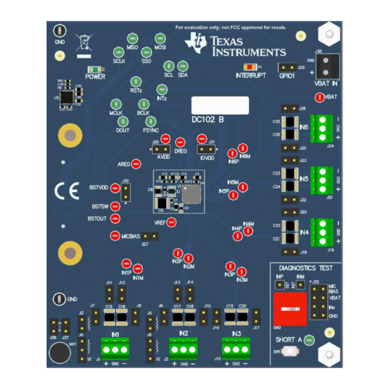
- Page 34 Test Points On Board On Board IN1/IN2/IN3 Microphone Microphone Input Terminals Connection and Control Headers Headers Figure 42. System Overview PCM6xx0Q1EVM-PDK Evaluation Module SBAU341B – January 2020 – Revised June 2020 Submit Documentation Feedback Copyright © 2020, Texas Instruments Incorporated...
- Page 35 PCM6260Q1EVM Schematic and Bill of Materials 7.1.1 PCM6260Q1EVM Schematic Figure 43 Figure 44 illustrate the schematics for the PCM6240Q1EVM. Figure 43. PCM6260Q1EVM-PDK Main DUT Schematics SBAU341B – January 2020 – Revised June 2020 PCM6xx0Q1EVM-PDK Evaluation Module Submit Documentation Feedback Copyright © 2020, Texas Instruments Incorporated...
- Page 36 Schematic and Bill of Materials www.ti.com Figure 44. PCM6260Q1EVM-PDK Connectors and Test Points Schematics PCM6xx0Q1EVM-PDK Evaluation Module SBAU341B – January 2020 – Revised June 2020 Submit Documentation Feedback Copyright © 2020, Texas Instruments Incorporated...
- Page 37 J11, J12, J13, J14, J16, Gold, TH J17, J19, J20, J22, J23, J25, J26, J27, J28, J29, J30, J31, J36, J37 SBAU341B – January 2020 – Revised June 2020 PCM6xx0Q1EVM-PDK Evaluation Module Submit Documentation Feedback Copyright © 2020, Texas Instruments Incorporated...
- Page 38 Stackpole Electronics Inc Q200 Grade 0, 0603 2.2k RES, 2.2 k, 5%, 0.063 W, 0402 CRCW04022K20JNED Vishay-Dale AEC-Q200 Grade 0, 0402 PCM6xx0Q1EVM-PDK Evaluation Module SBAU341B – January 2020 – Revised June 2020 Submit Documentation Feedback Copyright © 2020, Texas Instruments Incorporated...
- Page 39 Taiyo Yuden V, +/- 20%, X5R, 0603 CAP, CERM, 1 uF, 16 V, 0402 EMK105BJ105KVHF Taiyo Yuden +/- 10%, X5R, 0402 SBAU341B – January 2020 – Revised June 2020 PCM6xx0Q1EVM-PDK Evaluation Module Submit Documentation Feedback Copyright © 2020, Texas Instruments Incorporated...
- Page 40 Test Point, Miniature, Green Miniature 5116 Keystone TP28, TP29, TP30, Green, TH Testpoint TP31, TP32, TP33, TP34, TP35, TP36, TP37 PCM6xx0Q1EVM-PDK Evaluation Module SBAU341B – January 2020 – Revised June 2020 Submit Documentation Feedback Copyright © 2020, Texas Instruments Incorporated...
- Page 41 Converter with Forced PWM Mode, 2.3 to 6 V, -40 to 85 degC, 8-pin SOP (PW8), Green (RoHS & no Sb/Br) SBAU341B – January 2020 – Revised June 2020 PCM6xx0Q1EVM-PDK Evaluation Module Submit Documentation Feedback Copyright © 2020, Texas Instruments Incorporated...
- Page 42 Interrup t Mon itor Power LED On-Boa rd +3.3V Power Supp ly Control Interface Selection GPIO Selection Figure 45. PCM6240Q1EVM-PDK Main DUT Schematics PCM6xx0Q1EVM-PDK Evaluation Module SBAU341B – January 2020 – Revised June 2020 Submit Documentation Feedback Copyright © 2020, Texas Instruments Incorporated...
- Page 43 TP21 MCLK Digital Signal Test Points Power Test Points Connector to AC-MB Figure 46. PCM6xx0Q1EVM-PDK Connectors and Test Points Schematics SBAU341B – January 2020 – Revised June 2020 PCM6xx0Q1EVM-PDK Evaluation Module Submit Documentation Feedback Copyright © 2020, Texas Instruments Incorporated...
- Page 44 J17, J19, J20, J27, J28, J29, J30, J31, J36, J37 J4, J6 Header, 100mil, 3x1, 3x1 Header TSW-103-07-G-S Samtec Gold, TH PCM6xx0Q1EVM-PDK Evaluation Module SBAU341B – January 2020 – Revised June 2020 Submit Documentation Feedback Copyright © 2020, Texas Instruments Incorporated...
- Page 45 RES, 2.2 k, 5%, 0.063 W, 0402 CRCW04022K20JNED Vishay-Dale AEC-Q200 Grade 0, 0402 RES, 866, 1%, 0.1 W, 0603 CRCW0603866RFKEA Vishay-Dale AEC-Q200 Grade 0, 0603 SBAU341B – January 2020 – Revised June 2020 PCM6xx0Q1EVM-PDK Evaluation Module Submit Documentation Feedback Copyright © 2020, Texas Instruments Incorporated...
- Page 46 Taiyo Yuden +/- 10%, X5R, 0402 0.1uF CAP, CERM, 0.1 uF, 16 0402 885012205037 Wurth Elektronik V, +/- 10%, X7R, 0402 PCM6xx0Q1EVM-PDK Evaluation Module SBAU341B – January 2020 – Revised June 2020 Submit Documentation Feedback Copyright © 2020, Texas Instruments Incorporated...
- Page 47 TP5, TP6, TP7, TP8, Red, TH TP9, TP10, TP11, TP12, TP15, TP16, TP17, TP18, TP19, TP20, TP22, TP23, TP24, TP25 SBAU341B – January 2020 – Revised June 2020 PCM6xx0Q1EVM-PDK Evaluation Module Submit Documentation Feedback Copyright © 2020, Texas Instruments Incorporated...
- Page 48 Converter with Forced PWM Mode, 2.3 to 6 V, -40 to 85 degC, 8-pin SOP (PW8), Green (RoHS & no Sb/Br) PCM6xx0Q1EVM-PDK Evaluation Module SBAU341B – January 2020 – Revised June 2020 Submit Documentation Feedback Copyright © 2020, Texas Instruments Incorporated...
- Page 49 Interrup t Mon itor Power LED On-Boa rd +3.3V Power Supp ly Control Interface Selection GPIO Selection Figure 47. PCM6360Q1EVM-PDK Main DUT Schematics SBAU341B – January 2020 – Revised June 2020 PCM6xx0Q1EVM-PDK Evaluation Module Submit Documentation Feedback Copyright © 2020, Texas Instruments Incorporated...
- Page 50 TP21 MCLK Digital Signal Test Points Power Test Points Connector to AC-MB Figure 48. PCM6360Q1EVM-PDK Connectors and Test Points Schematics PCM6xx0Q1EVM-PDK Evaluation Module SBAU341B – January 2020 – Revised June 2020 Submit Documentation Feedback Copyright © 2020, Texas Instruments Incorporated...
- Page 51 250" Head Dia diameter and a 4-40 threading H3, H4 HEX STANDOFF 4-40 HEX STANDOFF 4-40 4804 Keystone NYLON 3/4" NYLON 3/4" SBAU341B – January 2020 – Revised June 2020 PCM6xx0Q1EVM-PDK Evaluation Module Submit Documentation Feedback Copyright © 2020, Texas Instruments Incorporated...
- Page 52 W, AEC-Q200 Grade 0, 0402 R12, R14, R23 2.2k RES, 2.2 k, 5%, 0.1 W, 0603 ERJ-3GEYJ222V Panasonic AEC-Q200 Grade 0, 0603 PCM6xx0Q1EVM-PDK Evaluation Module SBAU341B – January 2020 – Revised June 2020 Submit Documentation Feedback Copyright © 2020, Texas Instruments Incorporated...
- Page 53 Testpoint Automotive, 4-Channel RTV0032T PCM6360QRTVRQ1 Texas Instruments and 6-Channel Audio ADCs with Integrated Microphone Bias and Input Diagnostics, RTV0032T (WQFN-32) SBAU341B – January 2020 – Revised June 2020 PCM6xx0Q1EVM-PDK Evaluation Module Submit Documentation Feedback Copyright © 2020, Texas Instruments Incorporated...
- Page 54 Test Point, Miniature, Green Miniature 5116 Keystone TP28, TP29, TP30, Green, TH Testpoint TP31, TP32, TP33, TP34, TP35, TP36, TP37 PCM6xx0Q1EVM-PDK Evaluation Module SBAU341B – January 2020 – Revised June 2020 Submit Documentation Feedback Copyright © 2020, Texas Instruments Incorporated...
- Page 55 TPS389018DSER +1.8V Monitor +5V Input IOVDD Power LED Power On Circuit USB Power Select Figure 49. AC-MB Schematics Page 1 SBAU341B – January 2020 – Revised June 2020 PCM6xx0Q1EVM-PDK Evaluation Module Submit Documentation Feedback Copyright © 2020, Texas Instruments Incorporated...
- Page 56 0.1uF 0.1uF 0.1uF EVM-SPI-SS0 EVM-SPI-SS1 I²C Power Control Interface Translation Test Points EVM Connector Figure 50. AC-MB Schematics Page 2 PCM6xx0Q1EVM-PDK Evaluation Module SBAU341B – January 2020 – Revised June 2020 Submit Documentation Feedback Copyright © 2020, Texas Instruments Incorporated...
- Page 57 Sullins Connector Solutions Header, 100mil, 3x1, Gold, TH 3x1 Header TSW-103-07-G-S Samtec Terminal Block, 3.5mm Pitch, 2x1, TH 7.0x8.2x6.5mm ED555/2DS On-Shore Technology SBAU341B – January 2020 – Revised June 2020 PCM6xx0Q1EVM-PDK Evaluation Module Submit Documentation Feedback Copyright © 2020, Texas Instruments Incorporated...
- Page 58 TP7, TP8, TP9, TP10 Test Point, Multipurpose, Black, TH Black Multipurpose Testpoint 5011 Keystone IC MCU 512KB RAM, 128TQFP TQFP-128 XEF216-512-TQ128-C20 XMOS semiconductor PCM6xx0Q1EVM-PDK Evaluation Module SBAU341B – January 2020 – Revised June 2020 Submit Documentation Feedback Copyright © 2020, Texas Instruments Incorporated...
- Page 59 Red Miniature Testpoint 5000 Keystone TP3, TP4, TP5, TP6, TP11, Test Point, Miniature, Green, TH Green Miniature Testpoint 5116 Keystone TP12, TP13 SBAU341B – January 2020 – Revised June 2020 PCM6xx0Q1EVM-PDK Evaluation Module Submit Documentation Feedback Copyright © 2020, Texas Instruments Incorporated...
- Page 60 = audioDeviceReader( 'Device', 'TI USB Audio 2.0',… 'SampleRate', 48000, … 'NumChannels', 8 ,… 'BitDepth', '32-bit float',… 'OutputDataType','double'); elseif ispc % windows driver devoiceReader = audioDeviceReader( 'Driver','ASIO', 'Device', 'Texas Instruments USB Audio ...',… 'SampleRate', 48000, … 'NumChannels', 8 ,… 'BitDepth', '32-bit float',… 'OutputDataType','double’); setup(deviceReader);...
- Page 61 Deleted 2 V (normal mode) rows from Input Jumper Configuration table ............... • Changed AC-Coupled Line Input Biasing section for clarity SBAU341B – January 2020 – Revised June 2020 Revision History Submit Documentation Feedback Copyright © 2020, Texas Instruments Incorporated...
- Page 62 STANDARD TERMS FOR EVALUATION MODULES Delivery: TI delivers TI evaluation boards, kits, or modules, including any accompanying demonstration software, components, and/or documentation which may be provided together or separately (collectively, an “EVM” or “EVMs”) to the User (“User”) in accordance with the terms set forth herein.
- Page 63 www.ti.com Regulatory Notices: 3.1 United States 3.1.1 Notice applicable to EVMs not FCC-Approved: FCC NOTICE: This kit is designed to allow product developers to evaluate electronic components, circuitry, or software associated with the kit to determine whether to incorporate such items in a finished product and software developers to write software applications for use with the end product.
- Page 64 www.ti.com Concernant les EVMs avec antennes détachables Conformément à la réglementation d'Industrie Canada, le présent émetteur radio peut fonctionner avec une antenne d'un type et d'un gain maximal (ou inférieur) approuvé pour l'émetteur par Industrie Canada. Dans le but de réduire les risques de brouillage radioélectrique à...
- Page 65 www.ti.com EVM Use Restrictions and Warnings: 4.1 EVMS ARE NOT FOR USE IN FUNCTIONAL SAFETY AND/OR SAFETY CRITICAL EVALUATIONS, INCLUDING BUT NOT LIMITED TO EVALUATIONS OF LIFE SUPPORT APPLICATIONS. 4.2 User must read and apply the user guide and other available documentation provided by TI regarding the EVM prior to handling or using the EVM, including without limitation any warning or restriction notices.
- Page 66 Notwithstanding the foregoing, any judgment may be enforced in any United States or foreign court, and TI may seek injunctive relief in any United States or foreign court. Mailing Address: Texas Instruments, Post Office Box 655303, Dallas, Texas 75265 Copyright © 2019, Texas Instruments Incorporated...
- Page 67 TI products. TI’s provision of these resources does not expand or otherwise alter TI’s applicable warranties or warranty disclaimers for TI products. Mailing Address: Texas Instruments, Post Office Box 655303, Dallas, Texas 75265 Copyright © 2020, Texas Instruments Incorporated...
Need help?
Do you have a question about the PCM6 0Q1EVM-PDK Series and is the answer not in the manual?
Questions and answers