Table of Contents
Advertisement
Quick Links
The PCM186xEVM (EVM) is an easy-to-use evaluation board for the PCM186x family of ADCs. This
document details the materials received with the EVM, how to get started with the software and hardware,
the schematics, bill of materials (BOM), and layouts. Throughout this user's guide, the abbreviations EVM,
PCM186xEVM, and the term evaluation module are synonymous with the PCM1860EVM, PCM1861EVM,
PCM1862EVM, PCM1863EVM, PCM1864EVM, or PCM1865EVM, unless otherwise noted.
...................................................................................................................
1
2
2.1
2.2
2.3
3
3.1
3.2
3.3
......................................................................................................................
4
4.1
4.2
4.3
4.4
.....................................................................................................................
5
5.1
5.2
6
6.1
6.2
6.3
1
2
3
4
Block Diagram
5
6
7
8
9
Solder Options
10
11
....................................................................................................................
12
2
13
14
PurePath is a trademark of Texas Instruments.
Submit Documentation Feedback
...........................................................................................................
.......................................................................................................
......................................................................................................
...................................................................................................
...............................................................................................................
.......................................................................................
.......................................................................................................
.................................................................................................
...............................................................................................
..........................................................................................
...............................................................................................
......................................................................................................
..........................................................................................................
.........................................................................................
..............................................................................
.........................................................................................................
....................................................................................................
.............................................................................................................
...................................................................................................
..................................................................................................
................................................................................................................
.................................................................................
.....................................................................................................
......................................................................................................
......................................................................................................
...............................................................................................................
.......................................................................................................
........................................................................................
.................................................................................................
Copyright © 2014, Texas Instruments Incorporated
List of Figures
............................................................................
...........................................
User's Guide
SLAU615 - December 2014
PCM186xEVM
10
10
12
15
15
17
19
10
11
12
13
14
2
3
3
3
3
4
4
5
5
6
6
6
8
9
3
3
4
5
6
8
8
9
9
1
Advertisement
Table of Contents

Subscribe to Our Youtube Channel
Related Manuals for Texas Instruments PCM186xEVM


Summary of Contents for Texas Instruments PCM186xEVM
-
Page 1: Table Of Contents
SLAU615 – December 2014 PCM186xEVM The PCM186xEVM (EVM) is an easy-to-use evaluation board for the PCM186x family of ADCs. This document details the materials received with the EVM, how to get started with the software and hardware, the schematics, bill of materials (BOM), and layouts. Throughout this user's guide, the abbreviations EVM, PCM186xEVM, and the term evaluation module are synonymous with the PCM1860EVM, PCM1861EVM, PCM1862EVM, PCM1863EVM, PCM1864EVM, or PCM1865EVM, unless otherwise noted. -
Page 2: Contents 1 Introduction
PCM1864 PCM1865 The PCM186xEVM has an external +5-V power connection or USB +5 V through the USB-I2X board to power the EVM. In conjunction with the USB-I2X board, all of the register programming can be done via USB. In the case of the hardware-controlled parts, resistors are included to tie inputs high or low. There are headers and test points for most signals to and from the PCM186x. -
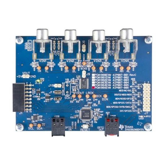
Page 3: What's In The Box
What’s in the Box? www.ti.com What’s in the Box? PCM186xEVM Figure 1 is a photo of the EVM. Figure 1. Picture of PCM186xEVM USB-I2X board Figure 2 is a photo of the USB-I2X board. Figure 2. Picture of USB-I2X Board Micro USB Cable A micro USB cable is also included in the box SLAU615 –... -
Page 4: Getting Started
Getting Started System Hardware Overview The PCM186xEVM can be controlled though the use of the USB using the included USB-I2X board. The USB-I2X board connects to a PC via USB and provides digital control signals to the EVM board via I2C. -
Page 5: Block Diagram
Software Download The EVM is controlled through the PurePath™ Console. Request PurePath Console access here: www.ti.com/tool/purepathconsole. Once access is granted, download the PurePath Console here: http://cc.ext.ti.com SLAU615 – December 2014 PCM186xEVM Submit Documentation Feedback Copyright © 2014, Texas Instruments Incorporated... -
Page 6: Hardware
Power Requirements The PCM186xEVM requires a 5-V power supply. This can be sourced from the I2X board via USB or applied directly to the EVM on the +5-V header just above J1. Once 5 V is applied, the PCM186x board regulates the 5 V down to a clean analog 3.3 V. -
Page 7: J7 Controls
PCM186x is used as a slave, remove the crystal. • Opto In – Opto in is the SPDIF input to the PCM9211. The PCM186x can mix this digital input with ADC output. SLAU615 – December 2014 PCM186xEVM Submit Documentation Feedback Copyright © 2014, Texas Instruments Incorporated... -
Page 8: Board Configurations
In mode 1, install Y0 and J10. Vin1 Vin2 Vin3 Vin4 PCM186x (Master) LRCK USB-I2X SCKI LRCK (Slave) PCM9211 SPDIF Opto Out Figure 7. Mode 1 Block Diagram PCM186xEVM SLAU615 – December 2014 Submit Documentation Feedback Copyright © 2014, Texas Instruments Incorporated... -
Page 9: Solder Options
For the proper settings of these multi- function pins, see the PCM186x data sheet (SLAS831). Tied High Tied Low Pass to J7 Figure 9. Solder Options SLAU615 – December 2014 PCM186xEVM Submit Documentation Feedback Copyright © 2014, Texas Instruments Incorporated... -
Page 10: Software
Figure 10. PCM186X EVM GUI Select Manually Choose a Target, a menu should appear that will show the list on installed plugins and the option to add a target. PCM186xEVM SLAU615 – December 2014 Submit Documentation Feedback Copyright © 2014, Texas Instruments Incorporated... -
Page 11: Manual Target Selection Window
Figure 11. Manual Target Selection Window If PCM186X does not appear in the list, select Add Target. Find the PCM186X plugin that was previously downloaded. SLAU615 – December 2014 PCM186xEVM Submit Documentation Feedback Copyright © 2014, Texas Instruments Incorporated... -
Page 12: Navigation And Features
To access the script editing area, click on the Direct I C Read/Write tab. PCM186xEVM SLAU615 – December 2014 Submit Documentation Feedback Copyright © 2014, Texas Instruments Incorporated... -
Page 13: Direct I 2 C Read/Write Tab
Vin1, and connect a system that accepts digital audio through the optical out. To improve performance, supply a differential audio signal to the part and select 1P-1M Differential and 2P-2M Differential in the Block Diagram tab. SLAU615 – December 2014 PCM186xEVM Submit Documentation Feedback Copyright © 2014, Texas Instruments Incorporated... -
Page 14: 1M Differential And 2P-2M Differential Shown In Block Diagram Tab
Software www.ti.com Figure 14. 1P-1M Differential and 2P-2M Differential Shown in Block Diagram Tab PCM186xEVM SLAU615 – December 2014 Submit Documentation Feedback Copyright © 2014, Texas Instruments Incorporated... -
Page 15: Schematics, Bill Of Materials And Layouts
Schematics, Bill of Materials and Layouts www.ti.com Schematics, Bill of Materials and Layouts Schematics Figure 15 Figure 16 are the schematics for the PCM186xEVM. PCM186xDBT EVALUATION BOARD ANALOG ANALOG IN2L INPUTS INPUTS DUAL FOOTPRINT IN3L IN2R DEFAULT: SMD0805 10uF/16V/X7R 2.20K 2.20K... -
Page 16: Pcm186Xevm Schematic, Spdif I/O And Controller Board I/O
SPDIF I/O, CONTROLLER BOARD I/O DATE NOVEMBER 12, 2013 SHEET DESIGN LEAD DAVID K. WILSON FILENAME PCM186xEVM_RevC.sbk DRAWN BY Figure 16. PCM186xEVM Schematic, SPDIF I/O and Controller Board I/O PCM186xEVM SLAU615 – December 2014 Submit Documentation Feedback Copyright © 2014, Texas Instruments Incorporated... -
Page 17: Bill Of Materials
Schematics, Bill of Materials and Layouts www.ti.com Bill of Materials Table 4 lists the PCM186xEVM BOM. Table 4. Bill of Materials for PCM186xEVM Item MANU PART NUM MANU REF DES Description PCM1865DBT TEXAS INSTRUMENTS MIC TO 2VRMS ANALOG IN 24-BIT 192 kHz STEREO FRONT END TSSOP30-DBT ROHS... - Page 18 Schematics, Bill of Materials and Layouts www.ti.com Table 4. Bill of Materials for PCM186xEVM (continued) Item MANU PART NUM MANU REF DES Description CRCW040210K0FKED VISHAY R30, R31, R32, R33 RESISTOR SMD0402 10.0K OHMS 1% 1/16W ROHS ERJ-3EKF1002V PANASONIC RESISTOR SMD0603 10.0K 1% THICK FILM 1/10W ROHS...
-
Page 19: Layouts
Schematics, Bill of Materials and Layouts www.ti.com Layouts Figure 17 through Figure 19 display the board layouts for the PCM186xEVM. Figure 17. Top Silk Screen Figure 18. Top copper SLAU615 – December 2014 PCM186xEVM Submit Documentation Feedback Copyright © 2014, Texas Instruments Incorporated... -
Page 20: Bottom Copper
Schematics, Bill of Materials and Layouts www.ti.com Figure 19. Bottom Copper PCM186xEVM SLAU615 – December 2014 Submit Documentation Feedback Copyright © 2014, Texas Instruments Incorporated... - Page 21 IMPORTANT NOTICE Texas Instruments Incorporated and its subsidiaries (TI) reserve the right to make corrections, enhancements, improvements and other changes to its semiconductor products and services per JESD46, latest issue, and to discontinue any product or service per JESD48, latest issue.
Need help?
Do you have a question about the PCM186xEVM and is the answer not in the manual?
Questions and answers