Table of Contents
Advertisement
Quick Links
www.ti.com
User's Guide
ADCx120Q1EVM-PDK, PCMD3140Q1EVM-PDK Evaluation
Module
This user's guide describes the function and use of the ADCx120Q1EVM-PDK and PCMD3140Q1EVM-PDK.
This document includes the hardware configuration instructions, a quick-start guide, jumper and connector
descriptions, software description, schematics, and printed circuit board (PCB) layout that demonstrate TI's
recommended practices for these devices.
1
Introduction.............................................................................................................................................................................3
2 Hardware Overview................................................................................................................................................................
Settings..................................................................................................................................................................3
2.2 ADCx120Q1EVM-PDK Hardware Settings........................................................................................................................
Overview................................................................................................................................................................12
Installation.......................................................................................................................................12
Settings......................................................................................................................................................................15
Operation........................................................................................................................................................16
Start.............................................................................................................................................................................16
Configuration.....................................................................................................................................................19
Materials...........................................................................................................................................20
7.1 ADCx120Q1EVM-PDK Schematic and Bill of Materials..................................................................................................
7.2 AC-MB Schematic and Bill of Materials...........................................................................................................................
7.3 Matlab Audio Capture Example.......................................................................................................................................
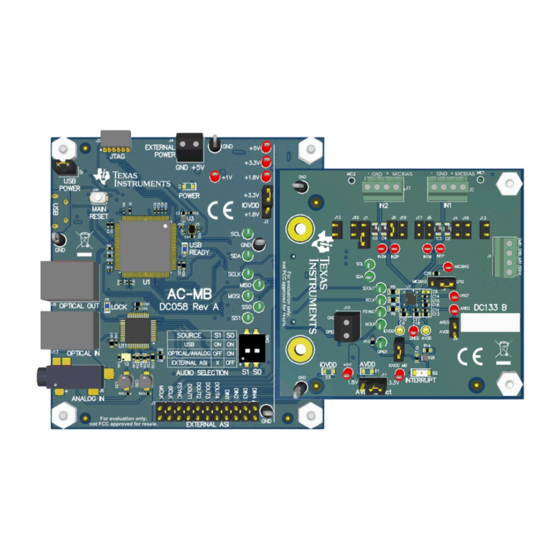
Figure 2-1. AC-MB Audio Serial Interface Routing......................................................................................................................
Figure 2-2. AC-MB USB Audio Setting........................................................................................................................................
Figure 2-3. AC-MB Optical or Auxiliary Analog Audio Setting.....................................................................................................
SBAU398 - MARCH 2022
Submit Document Feedback
ABSTRACT
Table of Contents
Installation....................................................................................................................................13
2
S Output........................................................................................................
List of Figures
Copyright © 2022 Texas Instruments Incorporated
ADCx120Q1EVM-PDK, PCMD3140Q1EVM-PDK Evaluation Module
Table of Contents
3
6
18
20
24
29
3
4
4
1
Advertisement
Table of Contents

Related Manuals for Texas Instruments ADCx120Q1EVM-PDK


Summary of Contents for Texas Instruments ADCx120Q1EVM-PDK
-
Page 1: Table Of Contents
Module ABSTRACT This user's guide describes the function and use of the ADCx120Q1EVM-PDK and PCMD3140Q1EVM-PDK. This document includes the hardware configuration instructions, a quick-start guide, jumper and connector descriptions, software description, schematics, and printed circuit board (PCB) layout that demonstrate TI's recommended practices for these devices. - Page 2 Table 7-1. ADCx120EVM-PDK Bill of Materials.........................21 Table 7-2. AC-MB Bill of Materials............................. Trademarks PurePath ™ is a trademark of Texas Instruments. Audio Toolbox ™ is a trademark of MathWorks. All trademarks are the property of their respective owners. ADCx120Q1EVM-PDK, PCMD3140Q1EVM-PDK Evaluation Module SBAU398 –...
-
Page 3: Introduction
Introduction 1 Introduction The ADCx120Q1EVM-PDK is an evaluation module (EVM) designed to demonstrate the performance and functionality of the PCMx120-Q1 family of devices. This family includes the devices shown in Table 1-1 with differences in performance and function noted. The family also includes the PCMD3140-Q1, which is the digital mic only version of the device. -
Page 4: Figure 2-2. Ac-Mb Usb Audio Setting
USB interface and PCM9211 are isolated with this setting. Figure 2-4 shows the AC-MB audio setting for the external mode of operation. Figure 2-4. AC-MB External Audio Setting ADCx120Q1EVM-PDK, PCMD3140Q1EVM-PDK Evaluation Module SBAU398 – MARCH 2022 Submit Document Feedback Copyright © 2022 Texas Instruments Incorporated... -
Page 5: Figure 2-5. Ac-Mb Connection With External Audio Serial
(USB or external). The voltage levels available are 1.8 V and 3.3 V, and can be selected via SBAU398 – MARCH 2022 ADCx120Q1EVM-PDK, PCMD3140Q1EVM-PDK Evaluation Module Submit Document Feedback Copyright © 2022 Texas Instruments Incorporated... -
Page 6: Adcx120Q1Evm-Pdk Hardware Settings
GPIOs, or in DC coupled applications. Figure 2-7 shows a diagram of the EVM input architecture. Figure 2-7. PCMx120-Q1EVB Input Architecture ADCx120Q1EVM-PDK, PCMD3140Q1EVM-PDK Evaluation Module SBAU398 – MARCH 2022 Submit Document Feedback Copyright © 2022 Texas Instruments Incorporated... -
Page 7: Figure 2-8. Pcmx120-Q1Evb Connection For Line Input
J2 (IN1) and J3 (IN2). The input accepted in this mode is a differential, 2-VRMS, full-scale audio signal. If a single-ended source is used, then 1-VRMS signal is supported Figure 2-8. PCMx120-Q1EVB Connection for Line Input Application SBAU398 – MARCH 2022 ADCx120Q1EVM-PDK, PCMD3140Q1EVM-PDK Evaluation Module Submit Document Feedback Copyright © 2022 Texas Instruments Incorporated... -
Page 8: Table 2-1. Onboard Mic Jumper Configuration
2.2.2 Onboard Microphone Configuration The ADCx120Q1EVM-PDK comes equipped with 2 onboard microphones: 1x ICS-40740 analog microphone and 1x T5818 digital microphone. The ICS-40740 can be connected to IN1 and the T5818 can be connected to IN2 with onboard shunts using the jumper settings shown in... -
Page 9: Figure 2-9. Onboard Mic Jumpers
9c 73 A0 #Enable input Ch-1 and Ch-3 w 9c 74 A0 # Enable ASI Output Ch-1 and Ch-3 slots w 9c 75 E0 # Power-up ADC, MICBIAS and PLL SBAU398 – MARCH 2022 ADCx120Q1EVM-PDK, PCMD3140Q1EVM-PDK Evaluation Module Submit Document Feedback Copyright © 2022 Texas Instruments Incorporated... -
Page 10: Figure 2-10. External Mics: 2X Analog Microphones
IN2M_GPO1 to generate the PDMCLK signal. AMIC1 AMIC2 Figure 2-10. External Mics: 2x Analog Microphones ADCx120Q1EVM-PDK, PCMD3140Q1EVM-PDK Evaluation Module SBAU398 – MARCH 2022 Submit Document Feedback Copyright © 2022 Texas Instruments Incorporated... -
Page 11: Figure 2-11. External Mics: 4X Digital Microphones
Figure 2-11. External Mics: 4x Digital Microphones AMIC1 AMIC2 DMIC1/2 AVDD AVDD PDMOUT AVDD PDMCLK *Requires AVDD = IOVDD Figure 2-12. External Mics: 2x Analog and 2x Digital Microphones SBAU398 – MARCH 2022 ADCx120Q1EVM-PDK, PCMD3140Q1EVM-PDK Evaluation Module Submit Document Feedback Copyright © 2022 Texas Instruments Incorporated... -
Page 12: Software Overview
3.1 PurePath Console 3 Installation The ADCx120Q1EVM-PDK GUI is an application that installs into the PPC3 framework. PPC3 must be installed prior to downloading the ADCx120Q1EVM-PDK GUI. To download the PPC3, visit www.ti.com/tool/... -
Page 13: Adcx120Q1Evm Gui Installation
The PCMx120-Q1 GUI is designed to work with up to four devices at any time. As shown in Figure 3-3, choose the 1 device radial button and click New. Figure 3-3. Initial GUI Configuration SBAU398 – MARCH 2022 ADCx120Q1EVM-PDK, PCMD3140Q1EVM-PDK Evaluation Module Submit Document Feedback Copyright © 2022 Texas Instruments Incorporated... -
Page 14: Figure 3-4. Audio Config Tab
Figure 3-5. Hardware Connect When the hardware is connected, the Connect button changes to read Disconnect, and the device is ready to be configured. ADCx120Q1EVM-PDK, PCMD3140Q1EVM-PDK Evaluation Module SBAU398 – MARCH 2022 Submit Document Feedback Copyright © 2022 Texas Instruments Incorporated... -
Page 15: Gpio1 Settings
GPIO1 is to be used a function other than interrupt, modifications may be required to the 0-Ω resistors installed. Figure 4-2 shows a schematic for the GPIO1 pin layout. Figure 4-1. GPIO1 Function and Output Drive Settings Figure 4-2. GPIO1 Schematic SBAU398 – MARCH 2022 ADCx120Q1EVM-PDK, PCMD3140Q1EVM-PDK Evaluation Module Submit Document Feedback Copyright © 2022 Texas Instruments Incorporated... -
Page 16: Master Mode Operation
Master Mode Operation www.ti.com 5 Master Mode Operation To operate ADCx120Q1EVM-PDK in master mode, S1 and S0 on the AC-MB must first be set to "External ASI" as illustrated in Figure 2-4. The device does not have a dedicated MCLK pin, the master clock can be applied at GPIO1, IN2P_GPI1, or MICBIAS_GPI2. -
Page 17: Figure 6-3. Mic Bias Configuration
Figure 6-5. Disabled Controls in Active Mode Audio can now be captured on your PC using the audio program of your choice. SBAU398 – MARCH 2022 ADCx120Q1EVM-PDK, PCMD3140Q1EVM-PDK Evaluation Module Submit Document Feedback Copyright © 2022 Texas Instruments Incorporated... -
Page 18: Configuring The Audio Serial Bus For The I
BCLK and FSYNC ratio. The ASI status register can also be read manually in the audio serial bus tab by clicking the Read button, as shown in Figure 6-8, in the clock monitor pane. Figure 6-8. Clock Monitor Pane ADCx120Q1EVM-PDK, PCMD3140Q1EVM-PDK Evaluation Module SBAU398 – MARCH 2022 Submit Document Feedback Copyright © 2022 Texas Instruments Incorporated... -
Page 19: Saving A Configuration
PPC3 window and select Open. Navigate to the location of the saved .ppc3 file, and click Open. Figure 6-10. Saving a Configuration in PPC3 SBAU398 – MARCH 2022 ADCx120Q1EVM-PDK, PCMD3140Q1EVM-PDK Evaluation Module Submit Document Feedback Copyright © 2022 Texas Instruments Incorporated... -
Page 20: Schematic And Bill Of Materials
Schematic and Bill of Materials www.ti.com 7 Schematic and Bill of Materials 7.1 ADCx120Q1EVM-PDK Schematic and Bill of Materials This section provides the schematics and bill of materials (BOM) for the ADCx120Q1EVM-PDK. 7.1.1 ADCx120Q1EVM-PDK Schematic Figure 7-1 shows the schematics for the ADCx120Q1EVM-PDK. -
Page 21: Table 7-1. Adcx120Evm-Pdk Bill Of Materials
Schematic and Bill of Materials 7.1.2 ADCx120Q1EVM-PDK Bill of Materials Table 7-1 lists the BOM for the ADCx120Q1EVM-PDK. Table 7-1. ADCx120EVM-PDK Bill of Materials Designator Quantity Value Description Package Part Number Manufacturer Reference C1, C7, C8 CAP, CERM, 1... - Page 22 Grade 0, 0603 SH1, SH2, SH3, Shunt, 100mil, Shunt SNT-100-BK-G Samtec SH4, SH5, SH6, Gold plated, Black SH7, SH8, SH9, SH10, SH11, SH12, SH13 ADCx120Q1EVM-PDK, PCMD3140Q1EVM-PDK Evaluation Module SBAU398 – MARCH 2022 Submit Document Feedback Copyright © 2022 Texas Instruments Incorporated...
- Page 23 Keystone Miniature, Red, Testpoint Please Note: Reference designator U1 has the below part numbers for different EVM’s ADC3120Q1EVM-PDK PCM3120-Q1 ADC5120Q1EVM-PDK PCM5120-Q1 ADC3120Q1EVM-PDK PCM6120-Q1 SBAU398 – MARCH 2022 ADCx120Q1EVM-PDK, PCMD3140Q1EVM-PDK Evaluation Module Submit Document Feedback Copyright © 2022 Texas Instruments Incorporated...
-
Page 24: Ac-Mb Schematic And Bill Of Materials
0.1uF 0.1uF 0.1uF 0.1uF 0.1uF 0.1uF 0.1uF 0.1uF EVM-SPI-SS0 EVM-SPI-SS1 I²C Power Control Interface Translation Test Points EVM Connector Figure 7-2. AC-MB Schematics ADCx120Q1EVM-PDK, PCMD3140Q1EVM-PDK Evaluation Module SBAU398 – MARCH 2022 Submit Document Feedback Copyright © 2022 Texas Instruments Incorporated... -
Page 25: Table 7-2. Ac-Mb Bill Of Materials
Standoff, Hex, Male/Female, 4-40, Nylon, Standoff, Hex, 4802 Keystone 1/2" Male/Female, 4-40, Nylon, 1/2" H11, H12 Standoff, Male/Male Thread, 5.15 mm, Standoff SO-0515-02-02-01 Samtec M3 x 0.5 SBAU398 – MARCH 2022 ADCx120Q1EVM-PDK, PCMD3140Q1EVM-PDK Evaluation Module Submit Document Feedback Copyright © 2022 Texas Instruments Incorporated... - Page 26 51.0k RES, 51.0 k, 1%, 0.05 W, 0201 0201 RC0201FR-0751K Yageo America 40.2k RES, 40.2 k, 1%, 0.063 W, AEC-Q200 0402 CRCW040240K2F Vishay-Dale Grade 0, 0402 ADCx120Q1EVM-PDK, PCMD3140Q1EVM-PDK Evaluation Module SBAU398 – MARCH 2022 Submit Document Feedback Copyright © 2022 Texas Instruments Incorporated...
- Page 27 Configurable Voltage-Level Shifting and 3-State Outputs, RSV0016A (UQFN-16) Photolink- Fiber Optic Receiver, TH 13.5x10x9.7mm PLR135/T10 Everlight Single Schmitt-Trigger Inverter, DCK0005A SN74LVC1G14DC Texas Instruments DCK0005A (SOT-SC70-5) SBAU398 – MARCH 2022 ADCx120Q1EVM-PDK, PCMD3140Q1EVM-PDK Evaluation Module Submit Document Feedback Copyright © 2022 Texas Instruments Incorporated...
- Page 28 Red Miniature 5000 Keystone TP15 Testpoint TP3, TP4, TP5, Test Point, Miniature, Green, TH Green Miniature 5116 Keystone TP6, TP11, TP12, Testpoint TP13 ADCx120Q1EVM-PDK, PCMD3140Q1EVM-PDK Evaluation Module SBAU398 – MARCH 2022 Submit Document Feedback Copyright © 2022 Texas Instruments Incorporated...
-
Page 29: Matlab Audio Capture Example
'SampleRate', 48000, … 'NumChannels', 8 ,… 'BitDepth', '32-bit float',… 'OutputDataType','double'); elseif ispc % windows driver devoiceReader = audioDeviceReader( 'Driver','ASIO', 'Device', 'Texas Instruments USB Audio ...',… 'SampleRate', 48000, … 'NumChannels', 8 ,… 'BitDepth', '32-bit float',… 'OutputDataType','double’); setup(deviceReader);% Setup the device reader % Play out a file through PC and capture in the EVM info = audioinfo( infile_name );% Read audiophile infile_name... - Page 30 TI products. TI’s provision of these resources does not expand or otherwise alter TI’s applicable warranties or warranty disclaimers for TI products. TI objects to and rejects any additional or different terms you may have proposed. IMPORTANT NOTICE Mailing Address: Texas Instruments, Post Office Box 655303, Dallas, Texas 75265 Copyright © 2022, Texas Instruments Incorporated...
Need help?
Do you have a question about the ADCx120Q1EVM-PDK and is the answer not in the manual?
Questions and answers