Table of Contents
Advertisement
Quick Links
INSTRUCTIONS-PARTS LIST
Parts
INSTRUCTIONS
ALUMINUM AND STAINLESS STEEL
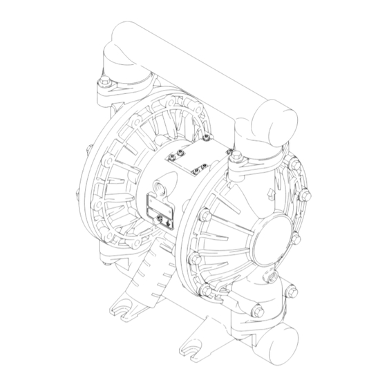
Huskyt 1590 Air-Operated
Diaphragm Pumps
120 psi (0.8 MPa, 8 bar) Maximum Fluid Working Pressure
120 psi (0.8 MPa, 8 bar) Maximum Air Input Pressure
*Model No. DB3____
*Model No. DB4____
*Model No. DBC____
*Model No. DBD____
Model No. 232502
1590 Pump (See page 22.)
*NOTE: Refer to the Pump Matrix on page 22 to
determine the Model No. of your pump.
US and Foreign Patents Pending
This manual contains important
warnings and information.
READ AND KEEP FOR REFERENCE.
Aluminum Pumps
Stainless Steel Pumps
Aluminum BSPT Pumps
Stainless Steel BSPT Pumps
Private-Label Aluminum
GRACO INC. P.O. BOX 1441 MINNEAPOLIS, MN 55440–1441
ECOPYRIGHT 1995, GRACO INC.
Graco Inc. is registered to I.S. EN ISO 9001
First choice when
quality counts.t
Aluminum Model
Shown
308441
Rev. U
03263B
Advertisement
Table of Contents

Related Manuals for Graco Husky 232502


Summary of Contents for Graco Husky 232502
- Page 1 *NOTE: Refer to the Pump Matrix on page 22 to determine the Model No. of your pump. US and Foreign Patents Pending Aluminum Model 03263B Shown GRACO INC. P.O. BOX 1441 MINNEAPOLIS, MN 55440–1441 ECOPYRIGHT 1995, GRACO INC. Graco Inc. is registered to I.S. EN ISO 9001...
-
Page 2: Table Of Contents
D Read all instruction manuals, tags, and labels before operating the equipment. D Use the equipment only for its intended purpose. If you are not sure, call your Graco distributor. D Do not alter or modify this equipment. Use only genuine Graco parts and accessories. - Page 3 WARNING TOXIC FLUID HAZARD Hazardous fluid or toxic fumes can cause serious injury or death if splashed in the eyes or on the skin, inhaled, or swallowed. D Know the specific hazards of the fluid you are using. D Store hazardous fluid in an approved container. Dispose of hazardous fluid according to all local, state and national guidelines.
-
Page 4: Installation
This pump must be grounded. Before operating the pump, ground the system as explained below. Also, read the sec- D Always use Genuine Graco Parts and Accessories. tion FIRE AND EXPLOSION HAZARD, Refer to Product Data Sheet 305646. on page 3. - Page 5 1/8 in. npt threads. WARNING 3. Connect remaining ends of tubes to external air signal, such as Graco’s Cycleflo (P/N 195264) or Cycleflo II (P/N195265) controllers. A bleed-type master air valve (B) is required in your system to relieve air trapped between this valve and the pump.
- Page 6 Installation Fluid Outlet Line 1. Use grounded fluid hoses (L). The pump fluid outlet (S) is 1–1/2” npt(f). Screw the fluid fitting into the pump outlet securely. 2. Install a fluid drain valve (J) near the fluid outlet. WARNING See the WARNING above. A fluid drain valve (J) is required to relieve pres- 3.
- Page 7 Installation Changing the Orientation of the Fluid Inlet Fluid Pressure Relief Valve and Outlet Ports CAUTION The pump is shipped with the fluid inlet (R) and outlet (S) ports facing the same direction. See Fig. 3. To Some systems may require installation of a pres- change the orientation of the inlet and/or outlet port: sure relief valve at the pump outlet to prevent overpressurization and rupture of the pump or...
- Page 8 Installation Air Exhaust Ventilation The air exhaust port is 3/4 npt(f). Do not restrict the air exhaust port. Excessive exhaust restriction can cause erratic pump operation. WARNING FIRE AND EXPLOSION HAZARD To provide a remote exhaust: Be sure to read and follow the warnings and precautions regarding TOXIC FLUID HAZARD, and FIRE OR EXPLO- 1.
-
Page 9: Operation
Operation Pressure Relief Procedure NOTE: If the fluid inlet pressure to the pump is more than 25% of the outlet working pressure, the ball check valves will not close fast enough, resulting in inefficient WARNING pump operation. PRESSURIZED EQUIPMENT HAZARD 4. -
Page 10: Maintenance
Maintenance Lubrication Flushing and Storage The air valve is designed to operate unlubricated, WARNING however if lubrication is desired, every 500 hours of operation (or monthly) remove the hose from the pump To reduce the risk of serious injury whenever you air inlet and add two drops of machine oil to the air are instructed to relieve pressure, always follow the inlet. - Page 11 Notes 308441...
-
Page 12: Troubleshooting
Troubleshooting D Relieve the pressure before checking or servicing WARNING the equipment. To reduce the risk of serious injury whenever you are instructed to relieve pressure, always follow the D Check all possible problems and causes before Pressure Relief Procedure on page 9. disassembling the pump. - Page 13 Troubleshooting PROBLEM CAUSE SOLUTION Fluid in exhaust air. Diaphragm ruptured. Replace. See pages 17–19. Loose diaphragm shaft bolt (107). Tighten or replace. See pages 17–19. Damaged o-ring (108). Replace. See pages 17–19. Pump exhausts excessive air at Worn air valve block (7), o-ring (6), Repair or replace.
-
Page 14: Repairing The Air Valve
Service Repairing the Air Valve Tools Required D Torque wrench D #2 phillips screwdriver or 7 mm (9/32”) socket wrench D Needle-nose pliers D O-ring pick D Lithium base grease NOTE: Air Valve Repair Kit 236273 is available. Refer to page 23. Parts included in the kit are marked with a symbol, for example (3{). - Page 15 Service Reassembly Insert narrow end first. 1. If you removed the bearings (12, 15), install new Grease. ones as explained on page 20. Reassemble the Install with lips facing fluid section. narrow end of piston (11). Insert wide end first. 2.
-
Page 16: Ball Check Valve Repair
Service Ball Check Valve Repair Apply medium-strength (blue) LoctiteR or equivalent to the threads. Torque to 120–150 in-lb (14–17 N.m). Tools Required Arrow (A) must point toward D Torque wrench outlet manifold (103). Not used on some models. D 13 mm socket wrench Beveled seating surface must face ball (301). -
Page 17: Diaphragm Repair
Service Diaphragm Repair WARNING Tools Required To reduce the risk of serious injury whenever you D Torque wrench are instructed to relieve pressure, always follow the Pressure Relief Procedure on page 9. D 13 mm socket wrench D 15 mm socket wrench (aluminum models) or 1”... - Page 18 Service 4. Loosen but do not remove the diaphragm shaft c. On PTFE models only, install the PTFE dia- bolts (107), using a 15 mm socket wrench (1” on phragm (403*). Make certain the side marked stainless steel models) on both bolts. AIR SIDE faces the center housing (1).
- Page 19 Service 402* 403* 401* 03274A 03275A Cutaway View, with Diaphragms in Place Cutaway View, with Diaphragms Removed 401* 403* 108* Lips face out of housing (1). Rounded side faces diaphragm (401). Air Side must face center housing (1). Grease. PTFE Used on pumps with diaphragms only.
-
Page 20: Bearing And Air Gasket Removal
Service Bearing and Air Gasket Removal 7. Use a bearing puller to remove the diaphragm shaft bearings (19), air valve bearings (12) or pilot Tools Required pin bearings (15). Do not remove undamaged D Torque wrench bearings. D 10 mm socket wrench 8. - Page 21 Service Insert bearings tapered end first. Press-fit bearings flush with surface of center housing (1). Apply medium-strength (blue) LoctiteR or equivalent. Torque to 130–150 in-lb (15–17 N.m). 03277 Detail of Air Valve Bearings 03278B Fig. 13 308441...
-
Page 22: Pump Matrix
Pump Matrix Husky 1590 Aluminum and Stainless Steel Pumps, Series A Your Model No. is marked on the pump’s serial plate. To determine the Model No. of your pump from the following matrix, select the six digits which describe your pump, working from left to right. The first digit is always D, designating Husky diaphragm pumps. -
Page 23: Repair Kit Matrix
Repair Kit Matrix For Husky 1590 Aluminum and Stainless Steel Pumps, Series A Repair Kits may be ordered separately. To repair the air valve, order Part No. 236273 (see page 25). Parts included in the Air Valve Repair Kit are marked with a symbol in the parts list, for example (3{). To repair your pump, select the six digits which describe your pump from the following matrix, working from left to right. -
Page 24: Parts
Parts Air Motor Parts List (Matrix Column 2) Fluid Section Parts List (Matrix Column 3) Ref. Ref. Digit Part No. Description Digit Part No. Description 189401 COVER, fluid; aluminum 188838 HOUSING, center; alum. 189402 MANIFOLD, inlet; 195921 HOUSING, center; re- aluminum mote 189403... - Page 25 Parts Drawing 14 F 110Y 301* 402* 201* 202* 13 F Aluminum Model Shown Not used on some models. 401* Used on PTFE models only. 108* 403* * These parts are included in the Pump Repair Kit, which may be purchased separately. Refer to the Repair Kit Matrix on page 23 to determine the correct kit for your pump.
- Page 26 Parts Fluid Section Parts List (Matrix Column 3) PTFE 202* 112418 O-RING; (continued) 201* 189319 SEAT; 17-4 stainless steel 4 Ref. PTFE 202* 112418 O-RING; Digit Part No. Description 201* 189322 SEAT; Hytrel 189401 COVER, fluid; aluminum None Not Used 192078 MANIFOLD, inlet;...
-
Page 27: Dimensions
Dimensions FRONT VIEW PUMP MOUNTING HOLE PATTERN 197 mm 6.0 in. 1/2 npt(f) (152.5 mm) Air Inlet 3/4 npt(f) Air Exhaust 6.0 in. (152.5 mm) 489 mm 482.5 mm 412.5 mm 268 mm 38 mm 152.5 mm 379.5 mm SIDE VIEW 5.23 in. -
Page 28: Technical Data
Technical Data Maximum fluid working pressure ..............120 psi (0.8 MPa, 8 bar) Air pressure operating range... -
Page 29: Performance Chart
Performance Chart Example of Finding Pump Air Consumption and Air Pressure at a Specific Fluid Delivery and Discharge Head: To supply 60 gpm (227 liters) fluid flow (horizontal scale) at 40 psi (0.28 MPa, 2.8 bar) discharge head pressure (vertical scale) re- quires approximately 50 scfm (1.40 m /min) air consumption at 70 psi (0.49 MPa, 4.9 bar) inlet air pressure. -
Page 30: Graco Standard Warranty
Graco distributor to the original purchaser for use. With the exception of any special, extended, or limited warranty published by Graco, Graco will, for a period of five years from the date of sale, repair or replace any part of the equipment determined by Graco to be defective.
Need help?
Do you have a question about the Husky 232502 and is the answer not in the manual?
Questions and answers