Advertisement
Quick Links
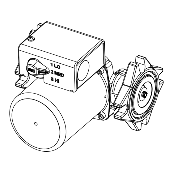
0010-MSF-IFC Multi-Speed Cartridge Circulator "Service Pump"
with Integral Flow Check and 4– olt Universal Flange
SUPERSEDES: May 1, 2010
Plant ID# 001-3904
APPLICATION:
Use the "Service Pump" to replace most commonly used circulators.
• Maximum operating pressure is 125 psi (862 kPa).
• Maximum water temperature not to exceed nameplate rating.
• Cast iron circulators are to be used for closed loop systems only.
• Taco Cartridge circulator pumps are for indoor use only – employer uniquement
a l interieur.
WARNING: Do not use in swimming pool or spa areas; pump has not been investigated for this
application.
WARNING: In the event the retaining screws have been pulled out of the housing, DO NOT replace
them. Use of any other screw may short out the stator windings, creating a risk of elec-
trical shock.
CAUTION: When installing electrical connections, do not apply mechanical loads to the capacitor
box; otherwise, retaining screws may be pulled out of the housing, making circulator
unusable.
CAUTION: 1. The addition of petroleum based fluids or certain chemical additives to systems
utilizing TACO equipment voids the warranty.
2. Use supply wires suitable for 90°C – ATTENTION: Employer des fils d alimentation
adequats pour 90°C.
WARNING: To avoid electrical shock, disconnect the power supply to the circulator and the main
electrical unit.
INSTALLATION:
1. Location – Install the "OO" circulator on the supply side of the boiler "pumping away" from the expansion tank as shown in
Figure 1. This is the best pump location for optimum system performance and maintaining positive system pressure. An alter-
nate location is on the boiler return line as shown in Figure 2.
CAUTION: Do not use flat rubber gaskets on pump flanges. Only use O-ring gaskets provided or
leaking will result. Warranty will be void.
2. Mounting position – Mount circulator with the motor in the horizontal position. It may be mounted vertically with the
motor up, provided that the system cold fill pressure is at least 20 psi (138 kPa) to ensure proper air purging and pre-
vent flashing.
3. Rotating body – Body has an arrow on the front that indicates direction of flow. To rotate body, remove the four body
bolts, rotate body and replace bolts. Make sure that the junction box is NOT located underneath the circulator. (The
junction box must NOT be located in the 6 o'clock position, as viewed from the motor end.)
4. Electrical connections – Observe all applicable codes when connecting to power supply.
The motor is impedance protected, and does not require additional overload protection.
Either colored wire from the capacitor box can be attached to either colored wire from the
power supply. There is no "hot" or "common" wire leading from the capacitor box. Typical
installation would be to attach the white wire to the white (common) power supply wire and
either the yellow or blue wire to the black (hot) power supply wire. The pump cannot run
backwards.
CAUTION: Installations at higher elevations over 5000 feet must have higher fill pressure of 20 psi
minimum to prevent pump cavitation and flashing. Premature failure may result. Adjust
expansion tank pressure to equal fill pressure. A larger size expansion tank may be required.
Instruction Sheet
102-232
EFFECTIVE: July 15, 2014
ELECTRICAL DATA
SPEED
Amps (Watts)
1
0.57 (62)
2
0.79 (88)
3
0.91 (109)
Advertisement

Subscribe to Our Youtube Channel
Related Manuals for Taco 0010-MSF-IFC


Summary of Contents for Taco 0010-MSF-IFC
- Page 1 • Maximum water temperature not to exceed nameplate rating. • Cast iron circulators are to be used for closed loop systems only. • Taco Cartridge circulator pumps are for indoor use only – employer uniquement a l interieur. WARNING: Do not use in swimming pool or spa areas; pump has not been investigated for this application.
- Page 2 5. Fill system with tap water – The system must be filled before operating the circulator. The bearings are water lubricat- ed and should not be allowed to operate dry. Filling the system will result in immediate lubrication of the bearings. It is always good practice to flush a new system of foreign matter before starting the circulator.
- Page 3 0010-MSF-IFC Multi-Speed Circulators 60 Hz PERFORMANCE FIELD: Flow (m^3/h) Low - Speed 1 Medium - Speed 2 High - Speed 3 9 10 11 12 13 14 15 16 17 18 19 20 21 22 23 24 25 26 27 28 29 30...
- Page 4 TACO, INC., 1160 Cranston Street, Cranston, RI 02920 Telephone: (401) 942-8000 FAX: (401) 942-2360. Copyright 2014 TACO (Canada), Ltd., 8450 Lawson Road, Unit #3, Milton, Ontario L9T 0J8. Telephone: 905/564-9422. FAX: 905/564-9436. TACO, Inc. Visit our web site at: http://www.taco-hvac.com...
Need help?
Do you have a question about the 0010-MSF-IFC and is the answer not in the manual?
Questions and answers