Advertisement
Quick Links
EFFECTIVE: August 9, 2019
A:
INSTALLATION
SAFETY REQUIREMENTS
It is important that you read and understand all the installation
instructions prior to beginning the installation of the unit.
A1:
RECEIVING, UNCRATING, AND INSPECTING
1.
Using the packing list as a guide, make certain that all equip-
ment arrived in the shipment and inspect for obvious damage
incurred during shipment.
2.
Immediately report any damage to carrier.
3.
Uncrate and lay out all the equipment in the order of installa-
tion on clean boards or floor.
A2:
INSTALLATION EQUIPMENT AND TOOLS
The following is a checklist of tools and equipment needed
for the installation. Assemble prior to starting the installation.
( )
1. A portable or permanent derrick of sufficient strength to
safely lift the total weight of the pump. A conservative
weight for the pump will be listed on the freight bill. The
minimum travel of the derrick should be at least 6' greater
than the longest piece of pump equipment. Hoist must
have swivel hook.
( )
2. One or two cable slings of sufficient strength to lift the
entire pump and long enough to clear greatest shaft pro-
jection.
( )
3. One erector sling for lifting the driver.
( )
4. Dial indicator calibrated in .001" divisions with a stand.
( )
5. Wire brush, paint brush, three-cornered file, flat file, and
emery cloth.
( )
6. Set of mechanic's tools including an assortment of socket
wrenches.
( )
7. Bucket of solvent, coal oil or naphtha, etc.
( )
8. Machinist's level
( )
9. Steel tape measure.
( ) 10. Two pipe wrenches of sufficient size to handle shaft and
couplings. (Always required for hollow shaft drive).
( ) 11. One set of steel clamps to fit the pump bowl.
( ) 12. Two sets of steel clamps to fit the column pipe. NOTE:
One set is required if only one section of column is fur-
nished with the pump assembly.
( ) 13. Two 4 x 4 timbers or "H" beams (if the unit is extra large
and heavy). Long enough to span the installation opening.
( ) 14. Two "V" blocks for checking shaft straightness.
( ) 15. Two chain tongs of sufficient size to handle column pipe.
( ) 16. Thread compound and gasket compound with thinner.
( ) 17. Sufficient quantity of wedges to level discharge head or
foundation plate (if applicable).
( ) 18. Sufficient quantity of top quality non-shrink grout.
( ) 19. Teflon Paste compound for stainless threads, anti-seize
compound for the other threads.
( ) 20. Bundle of cleaning rags.
( ) 21. Putty knife.
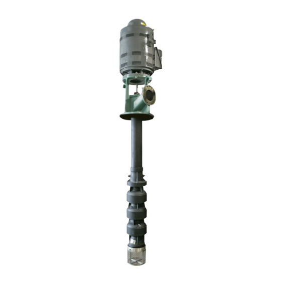
VT Series
Vertical Turbine Pumps
Installation and Operation Instructions
A3:
SPECIAL PRECAUTIONS
1.
Make certain that no rags, wood scraps, etc., are lodged in any
exposed openings. Check pit depth and anchor bolt spacing
with pump dimensions. Lift and handle unit carefully to prevent
bending strain damage caused by the hanging weight of the
unit. Do not lift any item by the shaft. Take extra precautions
when handling a mechanical seal or packing gland assembly
since this is a delicate and precision component.
ALWAYS USE THREAD COMPOUND ON SHAFT AND
2.
COLUMN JOINTS. Do not allow pipe compound, solvent, or
any petroleum products to get on the rubber bearings.
3.
Shaft threads are usually left hand; column threads are right
hand. If unit is shipped assembled, and has threaded
column pipe; pipe joints may have loosened during ship-
ment. Before installation check threaded connections for
tightness. A chain tong pipe wrench should be used to
verify tightness of pipe connections.
A4:
PREPARATION AND CLEANING
1.
Clean all threads and flange faces with a wire brush or paint
brush and solvent. If required, clean threads with a three-cor-
nered file. The protective coating on the threads and flanges
is a rust preventive coating and not a thread compound or
gasket material.
2.
Clean all shafts and couplings with a rag soaked in solvent.
Make certain that all bearings are clean.
3.
If applicable, remove protective caps from ends of oil tubing
and clean all tubing threads and shaft bearings thoroughly
with solvent. Make certain tubing faces are free of nicks,
dents, and burrs.
4.
Remove gland assembly from discharge head. Remember to
be very careful with this item.
5.
Make a physical check of the discharge head or foundation
plate for proper fit to foundation.
6.
Check pipe ends and couplings to be sure there are no dents,
nicks, or burrs.
7.
Check shaft end for nicks, burrs, etc. The shaft alignment is
dependent on the point of the shaft ends.
8.
Check all boxed shafting for straightness using "V" blocks
and dial indicator as follows:
8.a Start with "V" blocks as close to the threads as pos-
sible. Check two or more places between "V" blocks
and straighten shaft to within .003" to .005" of the Total
Indicated Run-Out. Straightening may be performed by
mechanical or high pressure on the high point.
8.b Move one "V" block about 20% of shaft length inward
from the end. Check between the "V" blocks and the
overhanging ends; straighten as in step 1 above.
8.c If straightening was required in Step 2 repeat Step 1.
Repeat the above steps until shaft checks within tolerance
in both positions. Wipe the shaft clean after checking.
302-053
SUPERSEDES: May 25, 2016
Advertisement

Subscribe to Our Youtube Channel
Related Manuals for Taco VT Series


Summary of Contents for Taco VT Series
- Page 1 VT Series 302-053 Vertical Turbine Pumps Installation and Operation Instructions EFFECTIVE: August 9, 2019 SUPERSEDES: May 25, 2016 INSTALLATION SPECIAL PRECAUTIONS SAFETY REQUIREMENTS Make certain that no rags, wood scraps, etc., are lodged in any exposed openings. Check pit depth and anchor bolt spacing It is important that you read and understand all the installation with pump dimensions.
- Page 2 Check run-out on bowl shaft extensions by placing dial indi- entrance of foreign matter during the next step in assembly. cator toward the end of the shaft and turning slowly making certain the shaft stays to one side of the upper most bowl bearing.
- Page 3 9.a If there is more than one section of threaded column, a center- tubing, the top of the tubing should be approximately 1 ing spider may be used. Slip the spider over the lineshaft with inches below the tension box mounting face of the head lock ring on top.
- Page 4 Solid Shaft Motor 2.a Inspect the seal assembly to be sure O-rings are included on the seal housing cover and the shaft sleeve. On the lock 2.a Slide the pump hub of the adjustable motor coupling onto the ring, be sure the lower set screws are tight and upper set head shaft and insert the key.
- Page 5 ELECTRICAL 3.a Connect the pressure gauge to the tap in the discharge and, if required, in the suction flange. Position dial face to facilitate OPERATION reading. 3.b Make drain pipe connections. Route piping so that it will not PRIOR TO START-UP interfere with normal maintenance procedures.
-
Page 6: Packing Replacement
When the packing has been compressed to the point that the Customer: gland is about to contact the upper face of the packing box, TACO Model: remove the gland, add one extra packing ring and re-adjust. If this fails to reduce the leakage, remove all of the packing Lateral: rings and repack with new rings. - Page 7 Figure G4.g Figure G4.d of the top packing ring to the top face of the packing box. This helps center the gland and minimizes cocking. See Figure G4.g. h. Permit sufficient leakage to keep the packing box running cool. Adequate leakage at this time is a necessity. Check the temperature of the leakage as well as the pump hous- ing.
-
Page 8: Inspection And Maintenance
PREVENTIVE MAINTENANCE Proper preventive maintenance consists of maintaining junction with the suggested preventive maintenance schedule records of operation hours, operating data, gauge readings, and below will reduce downtime and prevent costly breakdowns. service performed on the pump. Using this information in con- PREVENTIVE MAINTENANCE INTERNAL INSPECTION CHART FREQUENCY OF COMPONENT... -
Page 9: H: Trouble Shooting
TROUBLE SHOOTING TROUBLE SHOOTING INSUFFICIENT CAPACITY INSUFFICIENT PRESSURE 1. Speed too slow 1. Speed too slow (check voltage) 2. Impeller trimmed incorrectly 2. Impeller trimmed incorrectly 3. Impeller loose 3. Impeller loose 4. Impeller or bowl partially plugged 4. Impeller plugged 5. - Page 10 BEARINGS TROUBLE SOURCE PROBABLE CAUSE REMEDY Bearing seized or galling Check lubrication, look for plugged suction or evidence of Running dry without lubrication on shaft flashing. Bearing failure or bearing High temperature failure Check pump manufacturer for bearing temperature limits seized Excessive shaft wear under Rubber bearings will swell in hydrocarbon, H.S., and high...
-
Page 11: Ordering Parts
3. Remachine or replace 4. Incorrect type of packing ORDERING PARTS Please contact your TACO representative with the serial number of the pump for more information. The serial number of the pump can be found on the pump information tag. - Page 12 (Models FI, CI, FE, CE, KV, KS, TA) tion or repair. Taco, Inc. reserves the right to make changes in Taco, Inc. will repair or replace without charge Motors provided on commercial pumps are not details of design, construction, or arrangement of (at the Company’s option) any commercial pump...
Need help?
Do you have a question about the VT Series and is the answer not in the manual?
Questions and answers