Table of Contents
Advertisement
Installation, Operation, and Maintenance Manual
SUPERSEDES: January 14, 2014
Plant ID: 001-4208
1 SAFETY REQUIREMENTS. . . . . . . . . . . . . . . . . . . . 2
2 GENERAL INSTALLATION REQUIREMENTS. . . . . 2
2.1 Receiving Pump . . . . . . . . . . . . . . . . . . . . . . . . . 2
2.2 Location . . . . . . . . . . . . . . . . . . . . . . . . . . . . . . . 2
2.3 Foundation . . . . . . . . . . . . . . . . . . . . . . . . . . . . . 2
3 MAINTENANCE . . . . . . . . . . . . . . . . . . . . . . . . . . . . 2
3.1 Routine Inspections . . . . . . . . . . . . . . . . . . . . . . 2
3.2 Close Coupled Pumps . . . . . . . . . . . . . . . . . . . . 3
3.3 Close Coupled Motors . . . . . . . . . . . . . . . . . . . . 3
3.4 Mechanical Seal. . . . . . . . . . . . . . . . . . . . . . . . . 3
4 DIS-ASSEMBLY AND RE-ASSEMBLY. . . . . . . . . . . 3
4.1 General . . . . . . . . . . . . . . . . . . . . . . . . . . . . . . . 3
4.2 Dis-Assembly . . . . . . . . . . . . . . . . . . . . . . . . . . . 3
4.3 Re-Assembly . . . . . . . . . . . . . . . . . . . . . . . . . . . 3
5 PUMP PIPING - GENERAL. . . . . . . . . . . . . . . . . . . . 4
6 APPLICATION. . . . . . . . . . . . . . . . . . . . . . . . . . . . . . 4
7 MECHANICAL INSTALLATION . . . . . . . . . . . . . . . . 4
7.1 Location . . . . . . . . . . . . . . . . . . . . . . . . . . . . . . . 4
7.2 VFD Mounting to Pump . . . . . . . . . . . . . . . . . . . 4
7.3 VFD Mounting to Wall . . . . . . . . . . . . . . . . . . . . 6
7.4 Pump Piping - Detailed . . . . . . . . . . . . . . . . . . . 6
8 ELECTRICAL CONNECTIONS. . . . . . . . . . . . . . . . . 9
8.1 Exploded Views . . . . . . . . . . . . . . . . . . . . . . . . . 9
8.2 Electrical Installation . . . . . . . . . . . . . . . . . . . . 10
8.3 Grounding Requirements . . . . . . . . . . . . . . . . . 12
8.4 Typical Terminal Wiring Configurations . . . . . . 18
9 USER INTERFACE . . . . . . . . . . . . . . . . . . . . . . . . . 28
9.1 Local Control Panel . . . . . . . . . . . . . . . . . . . . . 28
9.2 Backup and Copying Parameter Settings . . . . 30
9.3 Password Protection . . . . . . . . . . . . . . . . . . . . 31
10 PUMP CONTROL SET-UPS . . . . . . . . . . . . . . . . . 34
10.1 SelfSensing Description . . . . . . . . . . . . . . . . . 34
10.2 Set-up Menu . . . . . . . . . . . . . . . . . . . . . . . . . 34
10.4 Constant Flow Control . . . . . . . . . . . . . . . . . . 35
10.5 Constant Pressure Control. . . . . . . . . . . . . . . 36
10.6 Sequencing (Standby Pump Alternation) . . . . 36
© 2017 Taco, Inc.
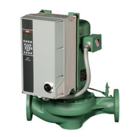
SKV SelfSensing
Vertical In-line Pump
Table of Contents
11 START-UP PROCEDURE . . . . . . . . . . . . . . . . . . 37
11.1 Check Points Before First Start . . . . . . . . . . . 37
11.2 Check Motor Rotation . . . . . . . . . . . . . . . . . . 37
11.3 Start Pump. . . . . . . . . . . . . . . . . . . . . . . . . . . 37
11.4 Verify Flow . . . . . . . . . . . . . . . . . . . . . . . . . . . 38
12 SYSTEM BALANCING . . . . . . . . . . . . . . . . . . . . . 39
12.1 About SelfSensing ProBalance . . . . . . . . . . . 39
12.2 My Personal Menu for ProBalance . . . . . . . . 40
12.3 Balancing Procedure . . . . . . . . . . . . . . . . . . . 41
12.4 Additional Settings . . . . . . . . . . . . . . . . . . . . . 49
13 MENUS . . . . . . . . . . . . . . . . . . . . . . . . . . . . . . . . . 50
14 WARNINGS AND ALARMS . . . . . . . . . . . . . . . . . 61
16 SKS PUMP PROBLEM ANALYSIS . . . . . . . . . . . 74
17 SPECIFICATIONS . . . . . . . . . . . . . . . . . . . . . . . . 75
17.1 Power-dependent Specifications . . . . . . . . . . 75
17.2 Connection Tightening Torques. . . . . . . . . . . 77
302-365
EFFECTIVE: June 5, 2017
1
Advertisement
Chapters
Table of Contents

Subscribe to Our Youtube Channel
Related Manuals for Taco SKV SelfSensing


Summary of Contents for Taco SKV SelfSensing
-
Page 1: Table Of Contents
10.4 Constant Flow Control ....35 10.5 Constant Pressure Control....36 10.6 Sequencing (Standby Pump Alternation) ..36 © 2017 Taco, Inc. -
Page 2: Safety Requirements
2.Hydraulic noise. 3.Mechanical noise in motor and/or pump. Inspect for shipping damage. If a shortage or damage • Check suction gauge reading and confirm that it is occurs, contact carrier immediately. normal. 302-365, Effective: June 5, 2017 © 2017 Taco, Inc. -
Page 3: Close Coupled Pumps
CAUTION: Allow pump to cool and secure suction and discharge valves before working on pump! Remove re-circulation line. Remove bolts holding cover/adapter to casing, pry cover/ adapter and motor assembly from casing. 302-365, Effective: June 5, 2017 © 2017 Taco, Inc. -
Page 4: Pump Piping - General
Do not install more than one expansion tank connection into any closed hydronic system. Electric motor driven pumps should not be located in damp or dusty location without special protection. 302-365, Effective: June 5, 2017 © 2017 Taco, Inc. - Page 5 WIRE HARNESS - MOTOR POWER VIBRATION ISOLATION MOUNT SAFETY STRAP NUT (VFD) LOCK WASHER (VFD) WASHER (VFD) "A" SCREW (MOTOR) LOCK WASHER (MOTOR) WASHER (MOTOR) ALTERNATIVE BRACKET VIEW "LOCTITE" (242; P/N 24231) 302-365, Effective: June 5, 2017 © 2017 Taco, Inc.
-
Page 6: Vfd Mounting To Wall
Item A is a back plate properly installed for required air- Figure 7-4: Hanger Supported, Pipe Mounted flow to cool the unit. NOTE: The pump should not be rigidly attached to the base/pad structure unless flexible couplings are used. 302-365, Effective: June 5, 2017 © 2017 Taco, Inc. - Page 7 Figure 7-5 illustrates such an arrangement with the piping supported at the ceiling and the vertical pump installed with a Taco Suction Dif- fuser (RSP) and Plus Two Multi-Purpose Valve. Figure 7-5: Pipe Mounted, Supported at Ceiling...
- Page 8 (Figure 7-12). NOTE: The pump should not be rigidly attached to the base/pad structure unless flexible couplings are used. 302-365, Effective: June 5, 2017 © 2017 Taco, Inc.
-
Page 9: Electrical Connections
Cable strain relief / PE ground USB connector Decoupling plate Serial bus terminal switch Grounding clamp (PE) Digital I/O and 24 V power supply Shielded cable grounding clamp and strain relief Control cable coverplate 302-365, Effective: June 5, 2017 © 2017 Taco, Inc. -
Page 10: Electrical Installation
• Wiring the AC line power to the adjustable frequency drive input terminals • Connecting control and serial communication wiring • After power has been applied, checking input and motor power; programming control terminals for their intended functions 302-365, Effective: June 5, 2017 © 2017 Taco, Inc. - Page 11 Failure to isolate power, motor and control wiring could result in less than optimum adjustable frequency drive and associ- ated equipment performance. 302-365, Effective: June 5, 2017 © 2017 Taco, Inc.
-
Page 12: Grounding Requirements
• Proper protective grounding for equipment with ground currents higher than 3.5 mA must be estab- lished, see Leakage Current (>3.5 mA). • A dedicated ground wire is required for input power, motor power and control wiring. 302-365, Effective: June 5, 2017 © 2017 Taco, Inc. - Page 13 1.Use a wire stripper to remove the insulation for proper grounding. 2.Secure the grounding clamp to the stripped portion of the wire with the screws provided. 3.Secure the grounding wire to the grounding clamp provided. 302-365, Effective: June 5, 2017 © 2017 Taco, Inc.
- Page 14 Size wiring based upon the input current of the adjustable frequency drive. • Comply with local and national electrical codes for cable sizes. • Connect 3-phase AC input power wiring to terminals L1, L2, and L3 (see Figure 8-11). 302-365, Effective: June 5, 2017 © 2017 Taco, Inc.
- Page 15 * No screws to tighten Or remove front cover by loosening attaching screws. - Does not exist See “Figure 8-13: Control Wiring Access for A4, A5, B1, B2, C1 and C2 Enclosures” on page 15. 302-365, Effective: June 5, 2017 © 2017 Taco, Inc.
- Page 16 Wiring to Control Terminals quency cable contact. Control terminal connectors can be unplugged from the adjustable frequency drive for ease of installation, as shown in Figure 8-15. 302-365, Effective: June 5, 2017 © 2017 Taco, Inc.
- Page 17 • When the status line at the bottom of the LCP reads “AUTO REMOTE COASTING” or “Alarm 60 External Interlock” is displayed, this indicates that the unit is ready to operate but is missing an input signal on ter- minal 27. 302-365, Effective: June 5, 2017 © 2017 Taco, Inc.
-
Page 18: Typical Terminal Wiring Configurations
+10 V DC 10 V DC analog supply voltage. 15mA max. [0] No Operation Analog input 53. [0] No Operation Analog input 54. AI Common Common for analog input. 302-365, Effective: June 5, 2017 © 2017 Taco, Inc. - Page 19 Taco® SKV Figure 8-18: Control Terminal Connectors 1-4 and Relay Output Locations Drive 1 Relay. Relay 1 is on the right in this view. Relay 2. 302-365, Effective: June 5, 2017 © 2017 Taco, Inc.
- Page 20 SHLD AOUT +10V A IN A IN +24V +24V D IN D IN D IN D IN D IN D IN Starting/Stopping Controller [5-10] [8] Start* Start: Closed * factory default 302-365, Effective: June 5, 2017 © 2017 Taco, Inc.
- Page 21 24 V DC, 0.1A Minimum terminal load on 1–3 (NC), 1–2 (NO), 4–6 (NC), 4–5 (NO) 24 V DC 10mA, 24 V AC 20mA Environment according to EN 60664–1 overvoltage category III/pollution degree 2 302-365, Effective: June 5, 2017 © 2017 Taco, Inc.
- Page 22 [Group 6-] [6-50] [5-10] [Group20-] [137] Speed* [8] Start* (See Table) 4-20 mA Start: Closed Set A54=I * factory default * factory default Figure 8-21: Location of Terminals 53 and 54 Switches 302-365, Effective: June 5, 2017 © 2017 Taco, Inc.
- Page 23 * To use AI 53, set parameters 6–14, 6–15, 6–17 and set 20–00 to “Analog Input 53.” To set up the controller with a transducer that is intended for external monitoring, as opposed to feedback to the con- troller, set the following parameters: 302-365, Effective: June 5, 2017 © 2017 Taco, Inc.
- Page 24 Maximum transducer input value. For example, for a 60 PSI transducer, set to 60 PSI. 6–27* Terminal 54 Live Zero Disabled * To use AI 53, set parameters 6–14, 6–15, 6–17 and set 20-00 to “Analog Input 53.” 302-365, Effective: June 5, 2017 © 2017 Taco, Inc.
- Page 25 6-25 Terminal 54 High Ref./Feedb. Value Maximum motor speed. For example, 2950 Hz. 6-27 Terminal 54 Live Zero Disabled. 20-00 Feedback 1 Source No Function * Set switch A54 = U 302-365, Effective: June 5, 2017 © 2017 Taco, Inc.
- Page 26 20-14 Maximum Reference/ Maximum transducer feedback Maximum reference/setpoint Feedback value. For example, for a 60PSI value. For example, for a 60PSI transducer, set to 60 PSI. transducer, set to 60 PSI. 302-365, Effective: June 5, 2017 © 2017 Taco, Inc.
- Page 27 For specific communication set-up information for Modbus RTU, refer to the document number MG92B102. For specific communication set-up information for BACnet, see documents MG14C102 and MG11D202. These documents can be downloaded from www.danfoss.com. 302-365, Effective: June 5, 2017 © 2017 Taco, Inc.
-
Page 28: User Interface
Figure 9-2: Status Display Display Menu Keys Menu keys are used for menu access for parameter set- up, toggling through status display modes during normal operation, and viewing fault log data. a.Display area 302-365, Effective: June 5, 2017 © 2017 Taco, Inc. - Page 29 WARN light comes on and text appears in the display area identifying the problem. ALARM A fault condition causes the red alarm light to flash and an alarm text is dis- played. 302-365, Effective: June 5, 2017 © 2017 Taco, Inc.
-
Page 30: Backup And Copying Parameter Settings
6.Remove power to the unit and wait for the display to turn off. 7.Apply power to the unit. Default parameter settings longer than normal. are restored during start-up. This may take slightly 8.Press [Reset] to return to operation mode. 302-365, Effective: June 5, 2017 © 2017 Taco, Inc. -
Page 31: Password Protection
1.Follow steps 1-6 in section 9.3.1 above. 2.Change parameter 0-61 to “[0] Full Access.” 3.Scroll Down to parameter 0-6* Password. 3.Press [OK]. The Main Menu Password is now disabled. 4.Press [OK]. 302-365, Effective: June 5, 2017 © 2017 Taco, Inc. - Page 32 9.3.5 Disable Password Protection for My Personal Menu 1.Follow steps 1-3 in in section 9.3.4 above. 2.Change parameter 0-66 to “[0] Full Access.” 3.Press [OK]. The Personal Menu password protection is now disabled. 302-365, Effective: June 5, 2017 © 2017 Taco, Inc.
- Page 33 1.Follow steps 1-4 in in section 9.3.4 above. 2.Scroll down to parameter 0-65 Personal Menu Password. 3.Press [OK]. 4.Adjust/Edit the password using the arrow keys. 5.Press [OK]. The Personal Menu Pasword is now changed. 302-365, Effective: June 5, 2017 © 2017 Taco, Inc.
-
Page 34: Pump Control Set-Ups
10 PUMP CONTROL SET-UPS 2.View the display to confirm the current set-up. 10.1 SelfSensing Description The Taco SelfSensing pump is a Taco pump equipped with a variable frequency drive (VFD) with SelfSensing control technology. SelfSensing control is an innovative concept in circulating pumps. Pump performance and characteristic curves are embedded in the memory of the speed controller during manufacture. -
Page 35: Variable Flow Control (Flow Compensation)
It is not always the case that the design duty point required will fall on the maximum speed of the pump and in the majority of cases (as shown in Figure 10-1 above) it will be at a reduced speed. 302-365, Effective: June 5, 2017 © 2017 Taco, Inc. -
Page 36: Constant Pressure Control
For detailed connections and settings for the pump’s onboard pump sequencer see “Appendix A: Set-Up for Standby Pump Alternation” on page 78. 10.6.2 External Pump Sequencers The SelfSensing pump can be sequenced with external pump sequencers. 302-365, Effective: June 5, 2017 © 2017 Taco, Inc. -
Page 37: Start-Up Procedure
Failure to ensure that the motor, sys- tem, and any attached equipment is ready for start could result in personal injury or equipment damage. 5.Press the [OK] button to enter “My Personal 302-365, Effective: June 5, 2017 © 2017 Taco, Inc. -
Page 38: Verify Flow
12.After the discharge valve is fully open, let the drive ramp up to the design flow point that was specified. IMPORTANT: Allow the pump enough time to settle out at the specified design flow. 302-365, Effective: June 5, 2017 © 2017 Taco, Inc. -
Page 39: System Balancing
For information about the step above, see sections 11.3 and 11.4. Figure 12-2: Measure System Resistance For information about the step above, see section 12.3.1. Figure 12-3: Reset Control Curve For information about the step above, see section 12.3.2. 302-365, Effective: June 5, 2017 © 2017 Taco, Inc. -
Page 40: My Personal Menu For Probalance
Motor Speed High Limit [Hz] one parameter to the next. 5.After you arrive at the parameter you wish to adjust, press the [OK] button. 6.Use the arrow buttons to select/adjust the parame- ter. 302-365, Effective: June 5, 2017 © 2017 Taco, Inc. -
Page 41: Balancing Procedure
2.To navigate on the keypad use the [OK] and [ARROW] buttons shown below. a.Parameter 0-10 Active Set-up. Before After b.You will know the change has happened when you see change to 302-365, Effective: June 5, 2017 © 2017 Taco, Inc. - Page 42 13.Press the [Off] Button. a.Wait for the pump to come to a complete stop before moving to the next step. After b.You will know the change has happened when you see change to 302-365, Effective: June 5, 2017 © 2017 Taco, Inc.
- Page 43 8.Change the Configuration Mode from “Closed Loop” to “Open Loop” then press OK. Before a.Parameter 1-00 = Configuration Mode. After Before 13.Scroll down to parameter 1-00 Configura- After tion Mode and press OK. 302-365, Effective: June 5, 2017 © 2017 Taco, Inc.
- Page 44 18.Change Sensorless Unit to GPM (press the [Up Arrow] button to reach the setting faster). IMPOR- TANT: Due to the change in parameters, the drive will default back to metric units. It is important to 302-365, Effective: June 5, 2017 © 2017 Taco, Inc.
- Page 45 7.Set the system’s flow at design point (flow value that was specified at the time of order is already displayed) and press [OK]. 1.Press the [Off] Button. 2.Press the [Quick Menus] button. 302-365, Effective: June 5, 2017 © 2017 Taco, Inc.
- Page 46 1-00 Configura- tion Mode and press OK. 14.Change Active Set-up from “Set-up 3” to “Set-up 1” then press OK. 18.Change the Configuration Mode from “Closed Loop” to “Open Loop” then press OK. 302-365, Effective: June 5, 2017 © 2017 Taco, Inc.
- Page 47 Design Pressure Head. Consult the online refer- ence look up table for your specific pump model to determine the relationship between static head pressure and VFD Speed requirements. Then press OK. 302-365, Effective: June 5, 2017 © 2017 Taco, Inc.
- Page 48 TANT: Due to the change in parameters, the drive will default back to metric units. It is important to set the units back to GPM for proper function. Then press OK. 302-365, Effective: June 5, 2017 © 2017 Taco, Inc.
-
Page 49: Additional Settings
12.4 Additional Settings Other settings that are set to enable the pump to operate on a control curve are: • Par. 22-80 (Flow Compensation), which should be set to ‘Enabled’ [1] 302-365, Effective: June 5, 2017 © 2017 Taco, Inc. - Page 50 Taco® SKV 302-365, Effective: June 5, 2017 © 2017 Taco, Inc.
- Page 51 Taco® SKV 302-365, Effective: June 5, 2017 © 2017 Taco, Inc.
- Page 52 Taco® SKV 302-365, Effective: June 5, 2017 © 2017 Taco, Inc.
- Page 53 Taco® SKV 302-365, Effective: June 5, 2017 © 2017 Taco, Inc.
- Page 54 Taco® SKV 302-365, Effective: June 5, 2017 © 2017 Taco, Inc.
- Page 55 Taco® SKV 302-365, Effective: June 5, 2017 © 2017 Taco, Inc.
- Page 56 Taco® SKV 302-365, Effective: June 5, 2017 © 2017 Taco, Inc.
- Page 57 Taco® SKV 302-365, Effective: June 5, 2017 © 2017 Taco, Inc.
- Page 58 Taco® SKV 302-365, Effective: June 5, 2017 © 2017 Taco, Inc.
- Page 59 Taco® SKV 302-365, Effective: June 5, 2017 © 2017 Taco, Inc.
- Page 60 Taco® SKV 302-365, Effective: June 5, 2017 © 2017 Taco, Inc.
-
Page 61: Warnings And Alarms
This action puts the adjustable fre- quency drive into a trip condition as described above and may be reset in any of those four ways. 302-365, Effective: June 5, 2017 © 2017 Taco, Inc. - Page 62 Overload of Digital Output On X30/7 (X) 5-33 Pwr. card supply 24 V supply low 1.8 V supply low Speed limit 1-86 AMA calibration failed AMA check Unom and Inom AMA low Inom AMA motor too big 302-365, Effective: June 5, 2017 © 2017 Taco, Inc.
- Page 63 Brake IGBT Heatsink temp Heatsink sensor Pwr.card supply Pwr.card temp Illegal PS config New spare parts New Type Code (X) Dependent on parameter Cannot be Auto reset via 14-20 Reset Mode 302-365, Effective: June 5, 2017 © 2017 Taco, Inc.
- Page 64 The intermediate circuit voltage (DC) is higher than the high voltage warning limit. The limit is dependent on the adjustable frequency drive voltage rating. The adjustable frequency drive is still active. 302-365, Effective: June 5, 2017 © 2017 Taco, Inc.
- Page 65 50. Check 1-93 Thermistor Source selects terminal 18 or 19. Record the value of the following parameters and contact your Danfoss supplier: 15-40 FC Type 15-41 Power Section 302-365, Effective: June 5, 2017 © 2017 Taco, Inc.
- Page 66 • Damaged heatsink fan. • Cycle power to the adjustable frequency drive and • Dirty heatsink. check that the fan operates briefly at startup. • Check the sensors on the heatsink and control card. 302-365, Effective: June 5, 2017 © 2017 Taco, Inc.
- Page 67 Internal fault. Contact yourDanfoss supplier or For X30/6, check the load connected to X30/6 or remove DanfossService Department. short-circuit connection. Check 5-32 Term X30/6 Digi Out Parameter value outside of min/max limits (MCB 101). 302-365, Effective: June 5, 2017 © 2017 Taco, Inc.
-
Page 68: Ama Motor Too Small
ALARM 50, AMA calibration failed WARNING/ALARM 65, Control card over temperature Contact your Danfoss supplier or Danfoss Service Department. The cutout temperature of the control card is 176°F [80 °C]. 302-365, Effective: June 5, 2017 © 2017 Taco, Inc. -
Page 69: Heatsink Temperature Low
Operating in this condition voids unit warranty. Cycle power to the unit to remove the warning. See the fire mode data in the alarm log. 302-365, Effective: June 5, 2017 © 2017 Taco, Inc. -
Page 70: Supplemental Warning And Alarm Settings
Definition: Dry-run = low power consumption and 60Hz high speed condition. Pump response options: • off [0], • warning + run [1] (Factory default mode for SelfSens- ing pump) • alarm + trip [2] 302-365, Effective: June 5, 2017 © 2017 Taco, Inc. - Page 71 1.Press [Main Menu]. 5.Press [OK]. 2.Scroll down to parameter 22-** Appl. Func- 6.Scroll down to parameter 22-26 Dry Pump tions. Function. 3.Press [OK]. Press [OK]. 7.Change parameter 22-26 to desired feature. 302-365, Effective: June 5, 2017 © 2017 Taco, Inc.
- Page 72 HP limit curve. Pump response options: • default VFD trips at 110% rated current [0]; • de-rate VFD when load exceeds rating via speed reduction [1]. (Factory default mode for SelfSensing pump) 302-365, Effective: June 5, 2017 © 2017 Taco, Inc.
-
Page 73: Casing/Impeller Wear Ring Clearances
5.875 .018 .014 6011 5.861 5.859 5.877 5.875 .018 .014 6013 5.861 5.859 5.877 5.875 .018 .014 8011 7.234 7.232 7.252 7.250 .020 .016 8013 7.734 7.732 7.752 7.750 .020 .016 302-365, Effective: June 5, 2017 © 2017 Taco, Inc. -
Page 74: Sks Pump Problem Analysis
4.Air in system. 5.Casing gasket defective. 16.0.5 Excessive Power Consumption 1.Speed too high. 2.System head lower than rating. 3.Specific gravity of liquid too high. 4.Mechanical defects. a.Shaft bent. b.Rotating elements bind. 302-365, Effective: June 5, 2017 © 2017 Taco, Inc. -
Page 75: Specifications
IP55, IP66 max. cable cross-section (line power, motor, 4, 4, 4 (12, 12, 12) brake and load sharing) [mm (AWG)] Max. cable cross-section with disconnect 6, 4, 4 (10, 12, 12) 302-365, Effective: June 5, 2017 © 2017 Taco, Inc. - Page 76 IP20 max. cable cross-section (line power, motor, brake and load sharing) [mm ]/[AWG] IP55, IP66 max. cable cross-section (line power, motor, brake and load sharing) [mm2]/[AWG] Max. cable cross-section with disconnect 302-365, Effective: June 5, 2017 © 2017 Taco, Inc.
-
Page 77: Connection Tightening Torques
14/24 14/24 22-30 45-55 45-55 45-55 37-45 75-90 75-90 14/24 14/24 For different cable dimensions x/y, where x <= 0.147 in [95 mm ] and y >= 0.147 in [95 mm 302-365, Effective: June 5, 2017 © 2017 Taco, Inc. -
Page 78: A Set-Up For Standby Pump Alternation
Taco® SKV APPENDIX A: SET-UP FOR STANDBY PUMP ALTERNATION This section describes how to alternate Taco SKV pump units based on elapsed time and how to configure the standby pump to energize in the event that the duty pump fails. - Page 79 Factory default is 24 hours. Maximum value is 99 hours. a.Parameter 13-20 = SL Controller Time. 4.On the Standby drive (Drive B), Press the [Status] button to get back to the main screen. 5.Press [OK]. 302-365, Effective: June 5, 2017 © 2017 Taco, Inc.
- Page 80 A switches to Set-up 2 , becoming the Standby Drive. b.Drive B switches to Set-up 1 , becoming the Lead Drive. 9.Repeate step 7 as desired. 10.The pumps are now ready for alternation. 302-365, Effective: June 5, 2017 © 2017 Taco, Inc.
- Page 81 [27] Logic rule 1 [27] Logic rule 1 13–52.0 SL controller action [30] Start timer 1 [30] Start timer 1 13–52.1 SL controller action [29] Start timer 0 [29] Start timer 0 302-365, Effective: June 5, 2017 © 2017 Taco, Inc.
- Page 82 [30] Start timer 1 [30] Start timer 1 13–52.4 SL controller action [29] Start timer 0 [29] Start timer 0 13–52.5 SL controller action [2] Select set-up 1 [2] Select set-up 1 302-365, Effective: June 5, 2017 © 2017 Taco, Inc.
-
Page 83: B On-Site Drive Mounting To Wall Or Pump
For electrical connections see Section “8 Electrical Con- in Table 23 on page 84. Check mark those nections” on page 9. items when completed. 302-365, Effective: June 5, 2017 © 2017 Taco, Inc. - Page 84 DANGER: HIGH VOLTAGE! Frequency converters contain high voltage when connected to AC mains. Installation, start-up and maintenance should be performed by qualified personnel only. Failure to comply could result in death or serious injury. 302-365, Effective: June 5, 2017 © 2017 Taco, Inc.
- Page 85 NOTE: AMA has already been completed by Taco on all pump-mounted VFDs. You will only need to run AMA if the wire/motor lead is different from the one supplied by Taco. 302-365, Effective: January 14, 2014 © 2017 Taco, Inc.
- Page 86 OBLIGATION ON THE PART OF TES. tor or Taco in writing and promptly deliver the suitable for use with a Taco product or part, or TACO WILL NOT BE LIABLE FOR ANY SPE- subject product or part, delivery prepaid, to the...
Need help?
Do you have a question about the SKV SelfSensing and is the answer not in the manual?
Questions and answers