
Subscribe to Our Youtube Channel
Related Manuals for Supermicro SuperServer SYS-221BT-HNR


Summary of Contents for Supermicro SuperServer SYS-221BT-HNR
- Page 1 SuperServer ® SYS-221BT-HNR SYS-221BT-HNTR SYS-221BT-HNC8R SYS-221BT-HNC9R USER’S MANUAL Revision 1.0d...
- Page 2 State of California, USA. The State of California, County of Santa Clara shall be the exclusive venue for the resolution of any such disputes. Supermicro's total liability for all claims will not exceed the price paid for the hardware product.
- Page 3 If you have any questions, please contact our support team at: support@supermicro.com This manual may be periodically updated without notice. Please check the Supermicro website for possible updates to the manual revision level. Secure Data Deletion A secure data deletion tool designed to fully erase all data from storage devices can be found on our website: https://www.supermicro.com/about/policies/disclaimer.cfm?url=/wdl/utility/...
-
Page 4: Table Of Contents
Preface Contents Chapter 1 Introduction 1.1 Overview ..........................9 1.2 System Features ........................11 Front View .........................11 Front View: SYS-221BT-HNR ...................12 Front View: SYS-221BT-HNTR ..................13 Front View: SYS-221BT-HNC8R ..................14 Front View: SYS-221BT-HNC9R ..................15 Control Panel .........................16 Rear View ..........................17 1.3 System Architecture ......................18 Main Components ......................18 System Block Diagram ......................19 1.4 Motherboard Layout ......................23... - Page 5 Preface Chassis Installation ......................32 Chapter 3 Maintenance and Component Installation 3.1 Removing Power .......................33 3.2 Accessing the System ......................34 Removing a Computing Node Drawer ................34 Removing the Chassis Cover ...................35 3.3 Processor and Heatsink Installation ...................36 Installation Overview ......................37 Removal Overview ......................37 Create the Processor Carrier Assembly ................38 Creating the PHM ......................42 Preparing the CPU Socket for Installation ................44...
- Page 6 Preface Fans ..........................62 Installing the Air Shroud ....................64 3.9 Power Supply ........................65 3.10 AIOM Card ........................66 3.11 Expansion Cards ........................67 3.12 Backplane ..........................72 3.13 Storage Adapters ......................72 3.14 Cable Routing Diagrams ....................73 All Flash NVMe Gen5 .......................73 NVMe and SATA .......................74 NVMe and SAS via onboard 3808 ..................75 NVMe and SAS via 3908 AOC ..................76 Chapter 4 Motherboard Connections...
- Page 7 Preface Creating NVMe RAID Configurations ................98 Status Indications ......................99 Hot-Swap Drives .......................99 Hot-unplug ........................99 Hot-plug .........................99 Related Information Links ....................99 Chapter 7 Troubleshooting and Support 7.1 Information Resources .....................100 Website ...........................100 Direct Links for the SYS-221BT-H Series System ............100 Direct Links for General Support and Information .............101 7.2 Baseboard Management Controller (BMC) ..............101 7.3 Troubleshooting Procedures ...................102 General Technique ......................102...
- Page 8 San Jose, CA 95131 U.S.A. Tel: +1 (408) 503-8000 Fax: +1 (408) 503-8008 Email: marketing@supermicro.com (General Information) Sales-USA@supermicro.com (Sales Inquiries) Government_Sales-USA@supermicro.com (Gov. Sales Inquiries) support@supermicro.com (Technical Support) RMA@supermicro.com (RMA Support) Webmaster@supermicro.com (Webmaster) Website: www.supermicro.com Europe Address: Super Micro Computer B.V.
-
Page 9: Chapter 1 Introduction
2U rackmount; (WxHxD) 17.6 x 3.5 x 28.8 in (447 x 88 x 730 mm) Notes: A Quick Reference Guide can be found on the product page of the Supermicro website. The following safety models associated with the SYS-221BT-H Series have been certified as... - Page 10 Chapter 1: Introduction System Models Models Storage Capabilities (per node) SYS-221BT-HNR Six NVMe drives via backplane and NVMe cables SYS-221BT-HNTR Six hybrid NVMe/SATA drives via backplane and NVMe and SATA cables SYS-221BT-HNC8R Six hybrid NVMe/SAS drives via backplane and NVMe cables and 3808 SAS card Six hybrid NVMe/SAS drives via backplane and NVMe cables, riser card, and 3908 add- SYS-221BT-HNC9R on card...
-
Page 11: System Features
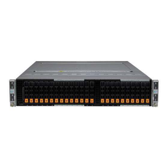
Chapter 1: Introduction 1.2 System Features The CSE-217BQ2-R3K04P is a 2U chassis that supports 24 front hot-swappable drives and four rear hot-pluggable nodes. Front View The chassis front offers access to the storage drives, a control panel for each node, and a pull-out service tag. -
Page 12: Front View: Sys-221Bt-Hnr
Chapter 1: Introduction Front View: SYS-221BT-HNR Figure 1-2. Front View Drive Bays Drive Bays (Node A - Node D) Description Two 2.5" Hot-Swap NVMe Gen 5 (CPU1) Drive Bays Four 2.5" Hot-Swap NVMe Gen 5 (CPU2) Drive Bays... -
Page 13: Front View: Sys-221Bt-Hntr
Chapter 1: Introduction Front View: SYS-221BT-HNTR Figure 1-3. Front View Drive Bays Drive Bays (Node A - Node D) Description Two 2.5" Hot-Swap NVMe Gen 5 (CPU1) Drive Bays Four 2.5" Hot-Swap NVMe Gen 5 (CPU2) Drive Bays... -
Page 14: Front View: Sys-221Bt-Hnc8R
Chapter 1: Introduction Front View: SYS-221BT-HNC8R Figure 1-4. Front View Drive Bays Drive Bays (Node A - Node D) Description Two 2.5" Hot-Swap NVMe Gen 5 (CPU1) Drive Bays Four 2.5" Hot-Swap NVMe Gen 5 (CPU2) Drive Bays... -
Page 15: Front View: Sys-221Bt-Hnc9R
Chapter 1: Introduction Front View: SYS-221BT-HNC9R Figure 1-5. Front View Drive Bays Drive Bays (Node A - Node D) Description Two 2.5" Hot-Swap NVMe Gen 5 (CPU1)/SAS Drive Bays Four 2.5" Hot-Swap NVMe Gen 4 (CPU2)/SAS Drive Bays... -
Page 16: Control Panel
Chapter 1: Introduction Control Panel Power Button NIC LED Information LED UID LED Node Label Figure 1-6. Control Panel (One Per Node) Control Panel Features (One Per Node) Feature Description The main power switch applies or removes primary power from the power supply to the Power Button server but maintains standby power. -
Page 17: Rear View
Chapter 1: Introduction Rear View Node Handle Power Supply Node D Node B Node A Dual Function Switch Node C BMC LAN USB Ports VGA Port Figure 1-7. System: Rear View System Features: Rear Feature Description Nodes A, B, C, D Independent computing nodes Power Supplies Two 3000 W redundant power supplies... -
Page 18: System Architecture
Chapter 1: Introduction 1.3 System Architecture This section covers the printed circuit board (PCB) locations and the system block diagrams. Main Components Storage Backplane Storage Adapter M.2 Card Carrier S A S C a r d f o r SYS-221BT-HNC8R Motherboard AIOM R i s e r C a r d f o r... -
Page 19: System Block Diagram
Chapter 1: Introduction System Block Diagram The block diagram below shows the connections and relationships between the subsystems and major components of the overall system. SYS-221BT-HNR Block Diagram DIMMA1 DIMMA1 DIMMB1 DIMMB1 DIMMC1 DIMMC1 DIMMD1 DIMMD1 12.8G/14.4G/16GT/s DIMME1 DIMME1 IMC0 4CH IMC0 4CH CPU#1 CPU#2... - Page 20 Chapter 1: Introduction SYS-221BT-HNTR Block Diagram DIMMA1 DIMMA1 DIMMB1 DIMMB1 DIMMC1 DIMMC1 DIMMD1 DIMMD1 12.8G/14.4G/16GT/s DIMME1 DIMME1 IMC0 4CH IMC0 4CH CPU#1 CPU#2 DIMMF1 DIMMF1 DIMMG1 DIMMG1 DDR5 DDR5 DIMMH1 DIMMH1 PECI:30 PECI:31 SOCKET ID:1 SOCKET ID:0 IMC1 4CH IMC1 4CH DMI3 DMI3 PCIe X8...
- Page 21 Chapter 1: Introduction SYS-221BT-HNC8R Block Diagram DIMMA1 DIMMA1 DIMMB1 DIMMB1 DIMMC1 DIMMC1 DIMMD1 DIMMD1 12.8G/14.4G/16GT/s DIMME1 DIMME1 IMC0 4CH IMC0 4CH CPU#1 CPU#2 DIMMF1 DIMMF1 DIMMG1 DIMMG1 DDR5 DDR5 DIMMH1 DIMMH1 PECI:30 PECI:31 SOCKET ID:1 SOCKET ID:0 IMC1 4CH IMC1 4CH DMI3 DMI3 PCIe X8...
- Page 22 Chapter 1: Introduction SYS-221BT-HNC9R Block Diagram DIMMA1 DIMMA1 DIMMB1 DIMMB1 DIMMC1 DIMMC1 DIMMD1 DIMMD1 12.8G/14.4G/16GT/s DIMME1 DIMME1 IMC0 4CH IMC0 4CH CPU#1 CPU#2 DIMMF1 DIMMF1 DIMMG1 DIMMG1 DDR5 DDR5 DIMMH1 DIMMH1 PECI:30 PECI:31 SOCKET ID:1 SOCKET ID:0 IMC1 4CH IMC1 4CH DMI3 DMI3 PCIe X8...
-
Page 23: Motherboard Layout
Chapter 1: Introduction 1.4 Motherboard Layout Below is a layout of the X13DET-B motherboard with jumper, connector and LED locations shown. See the table on the following page for descriptions. For detailed descriptions, pinout information and jumper settings, refer to Chapter 4 or the Motherboard Manual. -
Page 24: Quick Reference Table
BMC_LAN (IPMI_LAN1) Dedicated BMC LAN port on the I/O backplane COM1 (JCOM1) Serial/COM port header Supermicro Advanced input/output Module (AIOM) PCIe 5.0 x16 slot supported JAIOM by CPU1 NC-SI (Network Controller Sideband Interface) connector (See Note 1 on the JNCSI1 next page.) - Page 25 Network Interface Card Configuration User's Guide posted on our website under the link: http://www.supermicro.com/support/manuals/. Note 2: The SXB5 slot supports the SCC-P2HM2G4-B1 and the SCC-A2NM2241G3-B1. The SCC-P2HM2G4-B1 supports two NVMe M.2 devices (up to Gen 4) in the 22110 form factor, and the SCC-A2NM2241G3-B1 supports two NVMe M.2 devices (up to...
-
Page 26: Chapter 2 Server Installation
Chapter 2: Server Installation Chapter 2 Server Installation 2.1 Overview This chapter provides advice and instructions for mounting your system in a server rack. If your system is not already fully integrated with processors, system memory etc., refer to Chapter 3 for details on installing those specific components. -
Page 27: Rack Precautions
Chapter 2: Server Installation • This product is not suitable for use with visual display workplace devices according to §2 of the German Ordinance for Work with Visual Display Units. Rack Precautions • Ensure that the leveling jacks on the bottom of the rack are extended to the floor so that the full weight of the rack rests on them. -
Page 28: Airflow
Chapter 2: Server Installation Airflow Equipment should be mounted into a rack so that the amount of airflow required for safe operation is not compromised. Mechanical Loading Equipment should be mounted into a rack so that a hazardous condition does not arise due to uneven mechanical loading. - Page 29 Chapter 2: Server Installation To prevent bodily injury when mounting or servicing this unit in a rack, you must take special precautions to ensure that the system remains stable. The following guidelines are provided to ensure your safety: • This unit should be mounted at the bottom of the rack if it is the only unit in the rack. •...
-
Page 30: Rack Mounting Instructions
Chapter 2: Server Installation 2.4 Rack Mounting Instructions This section provides information on installing the chassis into a rack unit with the rails provided. There are a variety of rack units on the market, which may mean that the assembly procedure will differ slightly from the instructions provided. -
Page 31: Installing The Rails On A Rack
Chapter 2: Server Installation Installing the Rails on a Rack 1. Loosen the adjusting screw to allow the rear section to slide in the front section. 2. Push the small hooks on the front section of the rail into the holes on the front post of the rack and then down, until the spring-loaded pegs snap into the rack holes. -
Page 32: Chassis Installation
Chapter 2: Server Installation Chassis Installation Slide the chassis into the rack so that the bottom of the chassis slides onto the bottom lip of the rails. Figure 2-3. Sliding the Chassis into the Rack Stability hazard. The rack stabilizing mechanism must be in place, or the rack must be bolted to the floor before you slide the unit out for servicing. -
Page 33: Chapter 3 Maintenance And Component Installation
Chapter 3: Maintenance and Component Installation Chapter 3 Maintenance and Component Installation This chapter provides instructions on installing and replacing main system components. To prevent compatibility issues, only use components that match the specifications and/or part numbers given. Installation or replacement of most components require that power first be removed from the system. -
Page 34: Accessing The System
Chapter 3: Maintenance and Component Installation 3.2 Accessing the System Removing a Computing Node Drawer Node Handle Node Release Handle Figure 3-1. Removing a Node Tray Removing a Node 1. Use the operating system to power down the node. 2. Remove any cables attached to the node. 3. -
Page 35: Removing The Chassis Cover
Chapter 3: Maintenance and Component Installation Removing the Chassis Cover You can access some chassis components, such as fans, by removing the cover. Remove two screws Figure 3-2. Removing the Chassis Cover Removing the Chassis Cover The chassis top cover can be lifted off after removing two screws. Caution: Except for short periods of time, do not operate the server without the cover in place. -
Page 36: Processor And Heatsink Installation
Thermal grease is pre-applied on a new heatsink. No additional thermal grease is needed. • Refer to the Supermicro website for updates on processor and memory support. • All graphics in this manual are for illustrations only. Your components may look different. -
Page 37: Installation Overview
Chapter 3: Maintenance and Component Installation Installation Overview After preparing the system and following ESD precautions, there are four steps to installing the processor and heatsink onto the motherboard. 1. Attach the processor to a plastic carrier to create the processor carrier assembly. 2. -
Page 38: Create The Processor Carrier Assembly
Chapter 3: Maintenance and Component Installation Create the Processor Carrier Assembly Process Carrier Assembly 1. Hold the processor with the gold pins (LGA lands) facing down. Locate the gold triangle at the corner of the processor and the corresponding hollowed triangle on the processor carrier as shown below. - Page 39 Chapter 3: Maintenance and Component Installation 2. Turn the processor over (with the gold pins up). Locate the CPU keys on the processor and the four latches on the carrier as shown below. SP XCC Latch CPU Key Latch CPU Key Latch Latch CPU Key...
- Page 40 Chapter 3: Maintenance and Component Installation 3. Locate the lever on the CPU socket and press it down as shown below. Lever Lever Carrier E1B Carrier E1A 4. Using Pin 1 as a guide, carefully align the CPU keys (A and B) on the processor against the CPU keys on the carrier (a and b) as shown in the drawing below.
- Page 41 Chapter 3: Maintenance and Component Installation 6. After the processor is placed inside the carrier, examine the four sides of the processor, making sure that the processor is properly seated on the carrier. SP XCC (Top View) (Component View) CPU Carrier Assembly (Top View) (Component View) CPU Carrier Assembly...
-
Page 42: Creating The Phm
Chapter 3: Maintenance and Component Installation Creating the PHM After creating the processor carrier assembly, please follow the instructions below to mount the processor carrier into the heatsink to form the PHM. Note: If this is a new heatsink, the thermal grease has been pre-applied on the un- derside. - Page 43 Chapter 3: Maintenance and Component Installation CPU Carrier Assembly (CPU Component Side and Heatsink Bottom Side) SP XCC Pin 1 Pin 1 SP MCC Pin 1 Processor Heatsink Module (PHM)
-
Page 44: Preparing The Cpu Socket For Installation
Chapter 3: Maintenance and Component Installation Preparing the CPU Socket for Installation This motherboard comes with a plastic protective cover installed on the CPU socket. Remove it from the socket by following the instructions below: 1. Press the tabs inward. 2. -
Page 45: Installing The Phm Into The Cpu Socket
Chapter 3: Maintenance and Component Installation Installing the PHM into the CPU Socket 1. Locate four threaded fasteners (a, b, c, d) on the CPU socket. 2. Align PEEK nut A, which is next to the triangle (Pin 1) on the heatsink, against threaded fastener a on the CPU socket. -
Page 46: Removing The Phm From The Cpu Socket
Chapter 3: Maintenance and Component Installation Removing the PHM from the CPU Socket Before removing the PHM from the motherboard, be sure to shut down the system and unplug the power cables from the power supply. Then follow the steps below: 1. -
Page 47: Removing The Processor Carrier Assembly From The Phm
Chapter 3: Maintenance and Component Installation Removing the Processor Carrier Assembly from the PHM To remove the processor carrier assembly from the PHM, please follow the steps below: 1. Detach the four plastic clips (marked a, b, c, d) on the processor carrier assembly from the four corners of the heatsink (marked A, B, C, D) as shown in the drawings below. -
Page 48: Removing The Processor From The Processor Carrier Assembly
Chapter 3: Maintenance and Component Installation Removing the Processor from the Processor Carrier Assembly Once you have removed the processor carrier assembly from the PHM, you are ready to remove the processor from the processor carrier by following the steps below. 1. -
Page 49: Motherboard Installation
Chapter 3: Maintenance and Component Installation 3.4 Motherboard Installation All motherboards have standard mounting holes to fit different types of chassis. Make sure that the locations of all the mounting holes for both the motherboard and the chassis match. Although a chassis may have both plastic and metal mounting fasteners, metal ones are highly recommended because they ground the motherboard to the chassis. -
Page 50: Installing The Motherboard
Chapter 3: Maintenance and Component Installation Installing the Motherboard 1. Install the I/O shield into the back of the chassis, if applicable. 2. Locate the mounting holes on the motherboard. See the previous page for the location. 3. Locate the matching mounting holes on the chassis. Align the mounting holes on the motherboard against the mounting holes on the chassis. -
Page 51: Memory
Note: Memory speed and capacity support depend on the processors used in the system. For validated memory, use our Product Resources page. Check the Supermicro website for possible updates to memory support. Memory Installation Sequence Memory for this motherboard is populated using the "Fill First" method. The DIMM slots with blue release tabs are considered the first DIMM of their channel, and those with white release tabs are the second of the channel. -
Page 52: Ddr5 Memory Population Guidelines
Chapter 3: Maintenance and Component Installation DDR5 Memory Population Guidelines The following memory population table was created based on guidelines provided by Intel to support Supermicro motherboards. DDR5 Memory Population Table for X13DP Motherboards (with 16 DIMMs installed) 1 CPU:... - Page 53 Chapter 3: Maintenance and Component Installation Compatible and Incompatible Type in a Channel and a System DIMM Type RDIMM RDIMM 3DS 9x4 RDIMM RDIMM Compatible Incompatible Incompatible RDIMM 3DS Incompatible Compatible Incompatible 9x4 RDIMM Incompatible Incompatible Compatible...
-
Page 54: Dimm Installation
Chapter 3: Maintenance and Component Installation DIMM Installation JUIDB1 UID_LED1 JVGA1 JPME1 USB0/1 IPMI_LAN (3.1) SLOT1 1. Insert the desired number of DIMMs into the memory slots based on BIOS the recommended DIMM population tables in the previous section. SATA 8~11 JTPM1 P1 AIOM PCIe 5.0 X16 JAIOM... -
Page 55: Motherboard Battery
Chapter 3: Maintenance and Component Installation 3.6 Motherboard Battery The motherboard uses non-volatile memory to retain system information when system power is removed. This memory is powered by a lithium battery residing on the motherboard. Replacing the Battery Begin by removing the node from the system. -
Page 56: Storage Drives
Attention state---do not remove NVMe Amber Blinking at 1 Hz device (not supported in VMD mode) Note: Enterprise level hard disk drives are recommended for use in Supermicro chassis and servers. For information on recommended HDDs, see the Supermicro website, http://www. supermicro.com/products/nfo/files/storage/SBB-HDDCompList.pdf. -
Page 57: Drive Configuration
Chapter 3: Maintenance and Component Installation Drive Configuration The CSE-217BQ2 chassis contains four separate computing node drawers, each with its own motherboard. Each node controls a set of six drives. If a node drawer is pulled out of the chassis, the drives associated with that node will power down. Node Drawer Locations Node B controls drives B1, Node D controls drives D1,... -
Page 58: Installing Drives
Chapter 3: Maintenance and Component Installation Installing Drives Removing Drive Carriers from the Chassis 1. Press the release button on the drive carrier. This extends the drive carrier handle. 2. Use the handle to pull the carrier out of the chassis (Figure 3-5). 3. - Page 59 Chapter 3: Maintenance and Component Installation Figure 3-6. Removing a Dummy Drive from the Drive Carrier Installing a Drive 1. Install a new drive into the carrier with the printed circuit board side facing down so that the mounting holes in the drive align with those in the carrier. 2.
-
Page 60: Hot-Swap For Nvme Drives
Chapter 3: Maintenance and Component Installation Hot-Swap for NVMe Drives Supermicro servers support NVMe surprise hot-swap. For even better data security, NVMe orderly hot-swap is recommended. NVMe drives can be ejected and replaced remotely using BMC. Note: If you are using VROC, see the Hot-Swap Drives section in Chapter 6 instead. -
Page 61: Checking The Temperature Of An Nvme Drive
Chapter 3: Maintenance and Component Installation Checking the Temperature of an NVMe Drive There are two ways to check using BMC. Checking a Drive • BMC > Server Health > NVMe SSD – Shows the temperatures of all NVMe drives. •... -
Page 62: System Cooling
Chapter 3: Maintenance and Component Installation 3.8 System Cooling Fans Fan speed is controlled by a system temperature setting in BMC. If a fan fails, the remaining fans will ramp up to full speed. The system can continue to run with a failed fan. Replace any failed fan at your earliest convenience with the same type and model. - Page 63 Chapter 3: Maintenance and Component Installation Figure 3-10. Replacing a System Fan in the Fan Housing 6. Place the replacement fan into the vacant space in the housing while making sure the arrows on the top of the fan (indicating air direction) point in the same direction as the arrows on the other fans.
-
Page 64: Installing The Air Shroud
Chapter 3: Maintenance and Component Installation Installing the Air Shroud The system requires air shrouds for each node to maximize airflow efficiency. Installing the Air Shrouds The motherboard, any expansion cards, and all components must be installed in the node tray. Place the air shroud as pictured below. -
Page 65: Power Supply
3.9 Power Supply The chassis features redundant power supplies. The power modules can be changed without powering down the system. New units can be ordered directly from Supermicro or authorized distributors. These power supplies are auto-switching capable. This feature enables them to automatically sense the input voltage and operate at a 100-120 V or 180-240 V. -
Page 66: Aiom Card
3.10 AIOM Card The system supports various AIOM cards to provide networking functionality. See the Supermicro product page for details about the different AIOM cards. Removing the AIOM Card 1. Press the release tab and loosen the thumbscrew on the AIOM card. -
Page 67: Expansion Cards
Chapter 3: Maintenance and Component Installation 3.11 Expansion Cards The SYS-221BT-H Series supports two low-profile, half-length x16 expansion cards in each node. Riser cards are used to mount the expansion cards. Left Expansion Slot Right Expansion Slot Figure 3-15. PCI Slot Configuration Expansion Slot Locations (per node) Expansion Description (all PCIe... - Page 68 Chapter 3: Maintenance and Component Installation Populating Right Expansion Slot (SYS-221BT-HNC9R) 1. If necessary, power down the node and remove it from the chassis. 2. Open the latch at the center of the node and remove the I/O slot shield by sliding it towards the center.
- Page 69 Chapter 3: Maintenance and Component Installation 3. Attach the riser card to the riser card bracket and insert the expansion card into the riser card slot. 4. Align the assembly with slots on the motherboard and the PCI slot shield at the node rear.
- Page 70 Chapter 3: Maintenance and Component Installation Populating Left Expansion Slot (All Models) 1. If necessary, power down the node and remove it from the chassis. 2. Open the latch at the center of the node and remove the I/O slot shield by sliding it towards the center.
- Page 71 Chapter 3: Maintenance and Component Installation M.2 SSD Bracket Riser Slot Bracket Latch PCI Slot Figure 3-16. Installing Expansion Card 7. Check the PCIe bifurcation and the NVMe Firmware Source settings for the M.2 SSDs. • BIOS Setup -> Advanced -> Chipset Configuration -> North Bridge -> IIO Configuration -> CPU Configuration ->...
-
Page 72: Backplane
Chapter 3: Maintenance and Component Installation 3.12 Backplane The backplane (BPN-NVME5-217BHQ-S6) supports 24 SATA or NVMe drives. Four connectors are located at the back side of the backplane, one connected to each node. A cable linking the NearStack HD connector on the adapter to a high speed connector (P1 NS1) on the motherboard's PCB provides PCIe 5.0 support. -
Page 73: Cable Routing Diagrams
Chapter 3: Maintenance and Component Installation 3.14 Cable Routing Diagrams Refer to the storage cable diagrams in the next few pages. When disconnecting cables to add or replace components, refer to the diagrams so you can reroute them in the same manner. All Flash NVMe Gen5 NVMe connections from the backplane to the motherboard. -
Page 74: Nvme And Sata
Chapter 3: Maintenance and Component Installation NVMe and SATA NVMe connections from the backplane to the motherboard. SATA connections from the backplane to the motherboard. NVMe PCIe 5.0 Cable CBL-NSH5-1326 SATA Cable CBL-SAST-1243-100 Online Cable Matrix Figure 3-20. SYS-221BT-HNTR Cable Routing Diagram... -
Page 75: Nvme And Sas Via Onboard 3808
Chapter 3: Maintenance and Component Installation NVMe and SAS via onboard 3808 NVMe connections from the backplane to the motherboard. SAS connections from the backplane to the SCC-B8SB80-B1. The SCC-B8SB80-B1 connects to the motherboard SXB4. The SXB3 is blocked by the SCC-B8SB80-B1 and is unusable. NVMe PCIe 5.0 Cable CBL-NSH5-1326 SAS Cable... -
Page 76: Nvme And Sas Via 3908 Aoc
Chapter 3: Maintenance and Component Installation NVMe and SAS via 3908 AOC NVMe connections from the backplane to the motherboard. SAS connections from the backplane to the AOC-S3908L-H8iR-16DD. The riser card connects to the motherboard Slot 1. NVMe PCIe 5.0 Cable CBL-NSH5-1326 Hardware RAID Cable CBL-SAST-1234F-100... -
Page 77: Chapter 4 Motherboard Connections
Chapter 4: Motherboard Connections Chapter 4 Motherboard Connections This section describes the connections on the motherboard and provides pinout definitions. Note that depending on how the system is configured, not all connections are required. The LEDs on the motherboard are also described here. A motherboard layout indicating component locations may be found in Chapter 1. -
Page 78: Headers And Connectors
Chapter 4: Motherboard Connections 4.2 Headers and Connectors Fan Headers A 4-pin fan header (FAN3) is used for your system cooling fan. Fan speed control is supported by Thermal Management via the BMC 2.0 interface. VROC RAID Key Header A VROC RAID Key header is located at JRK1 on the motherboard. Install a VROC RAID Key on JRK1 for NVMe RAID support as shown in the illustration below. - Page 79 The JTPM1 header is used to connect a Trusted Platform Module (TPM)/Port 80, which is available from Supermicro (optional). A TPM/Port 80 connector is a security device that supports encryption and authentication in hard drives. It allows the motherboard to deny access if the TPM associated with the hard drive is not installed in the system.
- Page 80 Chapter 4: Motherboard Connections SATA 3.0 Ports 0~7/8~11 Two SATA 3.0 headers, located at (SATA1/SATA2), supports 12 SATA 3.0 connections (SATA 0~7 and SATA 8~11). These SATA 3.0 ports are supported by the Intel C741 Emmitsburg PCH chipset. Connecting proper SATA cables to SATA1 and SATA2 to use SATA 3.0 connections. AIOM PCIe 5.0 x16 Slot (JAIOM) A PCIe 5.0 x16 slot, supported by CPU1, is located at JAIOM.
-
Page 81: Input/Output Ports
Chapter 4: Motherboard Connections 4.3 Input/Output Ports VGA Connector A VGA connection is located at JVGA1 on the rear I/O panel. This VGA connector provides analog interface between the computer and the video displays. COM Port A COM (communication) port that supports serial link interface is located on the rear side of the motherboard. - Page 82 12 seconds, and it will trigger a cold reboot when the user presses and holds it for 6 seconds. Refer to the BMC User's Guide posted on our website at http://www.supermicro.com for more information.
-
Page 83: Jumpers
Chapter 4: Motherboard Connections 4.4 Jumpers How Jumpers Work To modify the operation of the motherboard, jumpers can be used to choose between optional settings. Jumpers create shorts between two pins to change the function of the connector. Pin 1 is identified with a square solder pad on the printed circuit board. Refer to the diagram below for an example of jumping pins 1 and 2. - Page 84 Chapter 4: Motherboard Connections ME Recovery JPME1 is used for ME Firmware Recovery mode, which will limit system resource for essential function use only without putting restrictions on power use. In the single operation mode, online upgrade will be available via Recovery mode. See the table below for pin definitions. ME Recovery (JPME1) Jumper Settings Jumper Setting...
-
Page 85: Led Indicators
Chapter 4: Motherboard Connections 4.5 LED Indicators BMC LAN LEDs A dedicated BMC LAN connection, located on the rear I/O panel, provides Ethernet network connection via the BMC (Baseboard Management Control). The LED on the right indicates activity, and the LED on the left indicates the speed of the connection. Refer to the table below for more information. -
Page 86: Chapter 5 Software
1. Create a method to access the MS Windows installation ISO file. That might be a USB flash or media drive, or the BMC KVM console. 2. Retrieve the proper RST/RSTe driver. Go to the Supermicro web page for your motherboard and click on "Download the Latest Drivers and Utilities", select the proper driver, and copy it to a USB flash drive. - Page 87 Chapter 5: Software 4. During Windows Setup, continue to the dialog where you select the drives on which to install Windows. If the disk you want to use is not listed, click on “Load driver” link at the bottom left corner. Figure 5-2.
-
Page 88: Driver Installation
The Supermicro website contains drivers and utilities for your system at https://www. supermicro.com/wdl/driver. Some of these must be installed, such as the chipset driver. After accessing the website, go into the CDR_Images (in the parent directory of the above link) and locate the ISO file for your motherboard. Download this file to a USB flash or media drive. -
Page 89: Superdoctor ® 5
5.3 SuperDoctor ® The Supermicro SuperDoctor 5 is a program that functions in a command-line or web-based interface for Windows and Linux operating systems. The program monitors such system health information as CPU temperature, system voltages, system power consumption, fan speed, and provides alerts via email or Simple Network Management Protocol (SNMP). -
Page 90: Bmc
There are several BIOS settings that are related to BMC. For general documentation and information on BMC, visit our website at: www.supermicro.com/en/solutions/management-software/bmc-resources BMC ADMIN User Password For security, each node is assigned a unique default BMC password for the ADMIN user. -
Page 91: Chapter 6 Optional Components
It enables the motherboard to deny access if the TPM associated with the hard drive is not installed in the system. Details and installation procedures are at: http://www.supermicro.com/manuals/other/TPM.pdf. • AOM-TPM-9670V •... -
Page 92: Intel Virtual Raid On Cpu (Vroc)
Chapter 6: Optional Components 6.3 Intel Virtual RAID on CPU (VROC) Intel Virtual RAID on CPU (Intel VROC) is an enterprise RAID solution for NVMe SSDs directly ® attached to Intel Xeon Scalable processors. Intel Volume Management Device (VMD) is an integrated controller inside the CPU PCIe root complex. -
Page 93: Additional Information
Chapter 6: Optional Components Additional Information Additional information is available on the product page for the Supermicro add-on card and the linked manuals. www.supermicro.com/products/accessories/addon/AOC-VROCxxxMOD.cfm Hardware Key The Intel VROC hardware key is a license key that detects the Intel VROC SKU and activates the function accordingly. -
Page 94: Configuring Intel Vmd
Chapter 6: Optional Components Configuring Intel VMD VMD must be enabled on PCIe ports which have NVMe drives attached to them in order for those drives to be added to a VROC RAID configuration. The default BIOS setting for the NVMe Mode Switch is Auto which automatically enables VMD on all installed NVMe drives. - Page 95 Chapter 6: Optional Components Note: Consult the X13DET-B Motherboard Manual for more detailed information on setting up Intel VMD. Caution: VMD must only be enabled on NVMe port resources. If VMD is enabled on other PCIe ports, the functionality of those ports will be impacted. See the table below. 4.
- Page 96 Chapter 6: Optional Components Figure 6-5. BIOS, Enabling VMD on Socket 1 (Example) 6. Enable the NVMe port resource according to table above for the NVMe drives that will be used in a RAID configuration. Figure 6-6. BIOS, Enabling Socket 1 (Example)
- Page 97 Chapter 6: Optional Components 7. Choose whether to make the NVMe drives in this IOU Hot Plug Capable by selecting Enabled or Disabled. 8. Repeat steps 4 through 7 for each IOU # on each CPU to enable VMD on the desired NVMe ports.
-
Page 98: Creating Nvme Raid Configurations
Chapter 6: Optional Components Creating NVMe RAID Configurations 1. Open Advanced > Intel(R) Virtual RAID on CPU > All Intel VMD Controllers > Create RAID Volume. Figure 6-8. Created Volume without Figure 6-9. Created Volume with enabling enabling RAID spanned over VMD RAID spanned over VMD controller controller 2. -
Page 99: Status Indications
Chapter 6: Optional Components Status Indications An LED indicator on the drive carrier shows the RAID status of the drive. Drive Carrier Status LED Indicator Status State (red) Normal function Locating 4 Hz blink Fault Solid ON Rebuilding 1 Hz Blink IBPI SFF 8489 Defined Status LED States Hot-Swap Drives Intel VMD enables hot-plug and hot-unplug for NVMe SSDs, whether from Intel or other... -
Page 100: Chapter 7 Troubleshooting And Support
Chapter 7: Troubleshooting and Support Chapter 7 Troubleshooting and Support 7.1 Information Resources Website A great deal of information is available on the Supermicro website, supermicro.com. Figure 7-1. Supermicro Website • Specifications for servers and other hardware are available by the Products option. •... -
Page 101: Direct Links For General Support And Information
Security Center for recent security notices Supermicro Phone and Addresses 7.2 Baseboard Management Controller (BMC) The system supports the Baseboard Management Controller (BMC). BMC is used to provide remote access, monitoring and management. There are several BIOS settings that are related to BMC. -
Page 102: Troubleshooting Procedures
Chapter 7: Troubleshooting and Support 7.3 Troubleshooting Procedures Use the following procedures to troubleshoot your system. If you have followed all of the procedures below and still need assistance, refer to the Technical Support Procedures Returning Merchandise for Service section(s) in this chapter. Power down the system before changing any non hot-swap hardware components. -
Page 103: No Video
• Memory: Make sure that the memory modules are supported. Refer to the product page on our website at www.supermicro.com. Test the modules using memtest86 or a similar utility. • Storage drives: Make sure that all drives work properly. Replace if necessary. - Page 104 Also check the Control panel Overheat LED. • Adequate power supply: Make sure that the power supply provides adequate power to the system. Make sure that all power connectors are connected. Refer to the Supermicro website for the minimum power requirements. •...
-
Page 105: Crash Dump Using Bmc
In the event of a processor internal error (IERR) that crashes your system, you may want to provide information to support staff. You can download a crash dump of status information using BMC. The BMC manual is available at https://www.supermicro.com/en/solutions/ management-software/bmc-resources. Check BMC Error Log 1. -
Page 106: Uefi Bios Recovery
Warning: Do not upgrade the BIOS unless your system has a BIOS-related issue. Flashing the wrong BIOS can cause irreparable damage to the system. In no event shall Supermicro be liable for direct, indirect, special, incidental, or consequential damages arising from a BIOS update. - Page 107 USB flash or media drive or a writable CD. Note 1: If you cannot locate the "Super.ROM" file in your drive disk, visit our website at www.supermicro.com to download the BIOS package. Extract the BIOS binary image into a USB flash device and rename it "Super.ROM"...
- Page 108 Chapter 7: Troubleshooting and Support Note: At this point, you may decide if you want to start the BIOS recovery. If you decide to proceed with BIOS recovery, follow the procedures below. 4. When the screen as shown above displays, use the arrow keys to select the item "Proceed with flash update"...
- Page 109 Chapter 7: Troubleshooting and Support 7. Press <Del> continuously during system boot to enter the BIOS Setup utility. From the top of the tool bar, select Boot to enter the submenu. From the submenu list, select Boot Option #1 as shown below. Then, set Boot Option #1 to [UEFI AP:UEFI: Built-in EFI Shell]. Press <F4>...
- Page 110 Chapter 7: Troubleshooting and Support Note: Do not interrupt this process until the BIOS flashing is complete. 9. The screen above indicates that the BIOS update process is complete. When you see the screen above, unplug the AC power cable from the power supply, clear CMOS, and plug the AC power cable in the power supply again to power on the system.
-
Page 111: Cmos Clear
Chapter 7: Troubleshooting and Support 7.6 CMOS Clear JBT1 is used to clear CMOS, which will also clear any passwords. Instead of pins, this jumper consists of contact pads to prevent accidentally clearing the contents of CMOS. To Clear CMOS 1. -
Page 112: Where To Get Replacement Components
7.7 Where to Get Replacement Components If you need replacement parts for your system, to ensure the highest level of professional service and technical support, purchase exclusively from our Supermicro Authorized Distributors/System Integrators/Resellers. A list can be found at: http://www.supermicro.com. -
Page 113: Vendor Support Filing System
For issues related to Red Hat Enterprise Linux, since it is a subscription based OS, contact your account representative. 7.9 Feedback Supermicro values your feedback as we strive to improve our customer experience in all facets of our business. Please email us at techwriterteam@supermicro.com to provide feedback on our manuals. -
Page 114: Appendix A Standardized Warning Statements For Ac Systems
Supermicro's Technical Support department for assistance. Only certified technicians should attempt to install or configure components. Read this appendix in its entirety before installing or configuring components in the Supermicro chassis. These warnings may also be found on our website at http://www.supermicro.com/about/... - Page 115 Appendix A: Warning Statements Warnung WICHTIGE SICHERHEITSHINWEISE Dieses Warnsymbol bedeutet Gefahr. Sie befinden sich in einer Situation, die zu Verletzungen führen kann. Machen Sie sich vor der Arbeit mit Geräten mit den Gefahren elektrischer Schaltungen und den üblichen Verfahren zur Vorbeugung vor Unfällen vertraut. Suchen Sie mit der am Ende jeder Warnung angegebenen Anweisungsnummer nach der jeweiligen Übersetzung in den übersetzten Sicherheitshinweisen, die zusammen mit diesem Gerät ausgeliefert wurden.
- Page 116 Appendix A: Warning Statements . ٌ ا ك ً ف حالة و ٌ يك أى تتسبب ف اصابة جسذ ة ٌ هذا الزهز ع ٌ خطز !تحذ ز قبل أى تعول عىل أي هعذات،يك عىل علن بالوخاطز ال ا ٌجوة عي الذوائز ٍ...
- Page 117 Appendix A: Warning Statements Warnung Vor dem Anschließen des Systems an die Stromquelle die Installationsanweisungen lesen. ¡Advertencia! Lea las instrucciones de instalación antes de conectar el sistema a la red de alimentación. Attention Avant de brancher le système sur la source d'alimentation, consulter les directives d'installation. .יש...
- Page 118 Appendix A: Warning Statements Warnung Dieses Produkt ist darauf angewiesen, dass im Gebäude ein Kurzschluss- bzw. Überstromschutz installiert ist. Stellen Sie sicher, dass der Nennwert der Schutzvorrichtung nicht mehr als: 250 V, 20 A beträgt. ¡Advertencia! Este equipo utiliza el sistema de protección contra cortocircuitos (o sobrecorrientes) del edificio.
- Page 119 Appendix A: Warning Statements 電源切断の警告 システムコンポーネントの取り付けまたは取り外しのために、 シャーシー内部にアクセスするには、 システムの電源はすべてのソースから切断され、 電源コードは電源モジュールから取り外す必要が あります。 警告 在你打开机箱并安装或移除内部器件前,必须将系统完全断电,并移除电源线。 警告 在您打開機殼安裝或移除內部元件前,必須將系統完全斷電,並移除電源線 。 Warnung Das System muss von allen Quellen der Energie und vom Netzanschlusskabel getrennt sein, das von den Spg.Versorgungsteilmodulen entfernt wird, bevor es auf den Chassisinnenraum zurückgreift, um Systemsbestandteile anzubringen oder zu entfernen.
- Page 120 Appendix A: Warning Statements يجب فصم اننظاو من جميع مصادر انطاقت وإ ز انت سهك انكهرباء من وحدة امداد انطاقت قبم انىصىل إىن امنناطق انداخهيت نههيكم نتثبيج أو إ ز انت مكىناث الجهاز 경고! 시스템에 부품들을 장착하거나 제거하기 위해서는 섀시 내부에 접근하기 전에 반드시 전원 공급장치로부터...
- Page 121 Appendix A: Warning Statements Attention Il est vivement recommandé de confier l'installation, le remplacement et la maintenance de ces équipements à des personnels qualifiés et expérimentés. !אזהרה .צוות מוסמך בלבד רשאי להתקין, להחליף את הציוד או לתת שירות עבור הציוד واملدربيه...
- Page 122 Appendix A: Warning Statements Warnung Diese Einheit ist zur Installation in Bereichen mit beschränktem Zutritt vorgesehen. Der Zutritt zu derartigen Bereichen ist nur mit einem Spezialwerkzeug, Schloss und Schlüssel oder einer sonstigen Sicherheitsvorkehrung möglich. ¡Advertencia! Esta unidad ha sido diseñada para instalación en áreas de acceso restringido. Sólo puede obtenerse acceso a una de estas áreas mediante la utilización de una herramienta especial, cerradura con llave u otro medio de seguridad.
- Page 123 Appendix A: Warning Statements Battery Handling Warning! There is the danger of explosion if the battery is replaced incorrectly. Replace the battery only with the same or equivalent type recommended by the manufacturer. Dispose of used batteries according to the manufacturer's instructions 電池の取り扱い...
- Page 124 Appendix A: Warning Statements هناك خطر من انفجار يف حالة اسحبذال البطارية بطريقة غري صحيحة فعليل اسحبذال البطارية فقط بنفس النىع أو ما يعادلها مام أوصث به الرشمة املصنعة جخلص من البطاريات املسحعملة وفقا لحعليامت الرشمة الصانعة 경고! 배터리가 올바르게 교체되지 않으면 폭발의 위험이 있습니다. 기존 배터리와 동일하거나 제 조사에서...
- Page 125 Appendix A: Warning Statements ¡Advertencia! Puede que esta unidad tenga más de una conexión para fuentes de alimentación. Para cortar por completo el suministro de energía, deben desconectarse todas las conexiones. Attention Cette unité peut avoir plus d'une connexion d'alimentation. Pour supprimer toute tension et tout courant électrique de l'unité, toutes les connexions d'alimentation doivent être débranchées.
- Page 126 Appendix A: Warning Statements Backplane Voltage Warning! Hazardous voltage or energy is present on the backplane when the system is operating. Use caution when servicing. バックプレーンの電圧 システムの稼働中は危険な電圧または電力が、 バックプレーン上にかかっています。 修理する際には注意く ださい。 警告 当系统正在进行时,背板上有很危险的电压或能量,进行维修时务必小心。 警告 當系統正在進行時,背板上有危險的電壓或能量,進行維修時務必小心。 Warnung Wenn das System in Betrieb ist, treten auf der Rückwandplatine gefährliche Spannungen oder Energien auf.
- Page 127 Appendix A: Warning Statements هناك خطز مه التيار الكهزبايئ أوالطاقة املىجىدة عىل اللىحة عندما يكىن النظام يعمل كه حذ ر ا عند خدمة هذا الجهاس 경고! 시스템이 동작 중일 때 후면판 (Backplane)에는 위험한 전압이나 에너지가 발생 합니다. 서비스 작업 시 주의하십시오. Waarschuwing Een gevaarlijke spanning of energie is aanwezig op de backplane wanneer het systeem in gebruik is.
- Page 128 Appendix A: Warning Statements תיאום חוקי החשמל הארצי !אזהרה .התקנת הציוד חייבת להיות תואמת לחוקי החשמל המקומיים והארציים تركيب املعدات الكهربائية يجب أن ميتثل للقىاويه املحلية والىطىية املتعلقة بالكهرباء 경고! 현 지역 및 국가의 전기 규정에 따라 장비를 설치해야 합니다. Waarschuwing Bij installatie van de apparatuur moet worden voldaan aan de lokale en nationale elektriciteitsvoorschriften.
- Page 129 Appendix A: Warning Statements Attention La mise au rebut ou le recyclage de ce produit sont généralement soumis à des lois et/ou directives de respect de l'environnement. Renseignez-vous auprès de l'organisme compétent. סילוק המוצר !אזהרה .סילוק סופי של מוצר זה חייב להיות בהתאם להנחיות וחוקי המדינה التخلص...
- Page 130 Appendix A: Warning Statements Warnung Gefährlich Bewegende Teile. Von den bewegenden Lüfterblätter fern halten. Die Lüfter drehen sich u. U. noch, wenn die Lüfterbaugruppe aus dem Chassis genommen wird. Halten Sie Finger, Schraubendreher und andere Gegenstände von den Öffnungen des Lüftergehäuses entfernt.
- Page 131 Verbindungskabeln, Stromkabeln und/oder Adapater, die Ihre örtlichen Sicherheitsstandards einhalten. Der Gebrauch von anderen Kabeln und Adapter können Fehlfunktionen oder Feuer verursachen. Die Richtlinien untersagen das Nutzen von UL oder CAS zertifizierten Kabeln (mit UL/CSA gekennzeichnet), an Geräten oder Produkten die nicht mit Supermicro gekennzeichnet sind.
- Page 132 .قيرح وأ لطع يف ببستي دق ىرخأ تالوحمو تالباك يأ مادختسا .ميلسلا سباقلاو لصوملا مجح لبق نم ةدمتعملا تالباكلا مادختسا تادعملاو ةيئابرهكلا ةزهجألل ةمالسلا نوناق رظحيUL وأCSA ( ةمالع لمحت يتلاوUL/CSA) لبق نم ةددحملاو ةينعملا تاجتنملا ريغ ىرخأ تادعم يأ عمSupermicro.
- Page 133 사항을 준수하여 제공되거나 지정된 연결 혹은 구매 케이블, 전원 케이블 및 AC 어댑터를 사용하십시오. 다른 케이블이나 어댑터를 사용하면 오작동이나 화재가 발생할 수 있습니다. 전기 용품 안전법은 UL 또는 CSA 인증 케이블 (코드에 UL / CSA가 표시된 케이블)을 Supermicro 가 지정한 제품 이외의 전기 장치에 사용하는 것을 금지합니다. Stroomkabel en AC-Adapter...
-
Page 134: Appendix B System Specifications
Appendix B: System Specifications Appendix B System Specifications Processors (per node) Supports dual 4th Gen Intel Xeon Scalable Processors (in Socket E LGA4677) with four UPIs (max 16GT/s) and a TDP (thermal design power) of up to 350 W per node. Supports SP XCC, SP MCC, and HBM SKU on the X13DET-B. Note: Refer to the motherboard specifications pages on our website for updates to supported processors. - Page 135 Appendix B: System Specifications Power Supply Model: PWS-3K04A-1R, 3000 W redundant module, 80Plus Titanium level Input voltages, input currents 1400W: 100-127Vac, 16-13A 2880W: 200-207Vac, 16-15.5A 3000W: 208-240Vac, 16-14A 3000W: 240Vdc, 14A (CQC only) Rated Frequency 50-60Hz Output DC Voltage: Input current +12 V: 116A (1400W) +12 V: 240A (2880W) +12 V: 250A (3000W)
- Page 136 Appendix B: System Specifications Perchlorate Warning California Best Management Practices Regulations for Perchlorate Materials: This Perchlorate warning applies only to products containing CR (Manganese Dioxide) Lithium coin cells. “Perchlorate Material-special handling may apply. See www.dtsc.ca.gov/ hazardouswaste/perchlorate”...
-
Page 137: Bsmi/Rohs
Appendix B: System Specifications BSMI/RoHS 限用物質含有情況標示聲明書 Declaration of the Presence Condition of the Restricted Substances Marking 設備名稱:伺服器 / Server 型號(型式): 217B-R30X13 Type designation (Type) Equipment name (系列型號: 217B-30, 217B-R22X13, 217B - 22, 827B-R30X13, 827B-30, 827B -R22X13, 827B -22, SYS-221BT-HNTR, SYS-221BT-HNR, SYS-221BT-HNC8R, SYS-221BT-HNC9R, SYS-621BT-HNTR, SYS-621BT-HNC8R) 限用物質及其化學符號... - Page 138 Appendix B: System Specifications 警告: 為避免電磁干擾, 本產品不應安裝或使用於住宅環境。 輸入額定 PWS-2K22A-1R 100-127V ~, 60-50Hz, 12-11A (X2) 200-240V ~, 60-50Hz, 10-9.8A (X2) PWS-3K04A-1R 100-127V ~, 60-50Hz, 16-13A (X2) 200-240V ~, 60-50Hz, 16-14A (X2) *使用者不能任意拆除或替換內部配備 *報驗義務人之姓名或名稱:美超微電腦股份有限公司 *報驗義務人之地址:新北市中和區建一路 150 號 3 樓...
- Page 139 Appendix B: System Specifications...
- Page 140 Appendix B: System Specifications...
- Page 141 Appendix B: System Specifications...
Need help?
Do you have a question about the SuperServer SYS-221BT-HNR and is the answer not in the manual?
Questions and answers