Table of Contents

Subscribe to Our Youtube Channel
Related Manuals for CTC Union GSi-12 BE


Summary of Contents for CTC Union GSi-12 BE
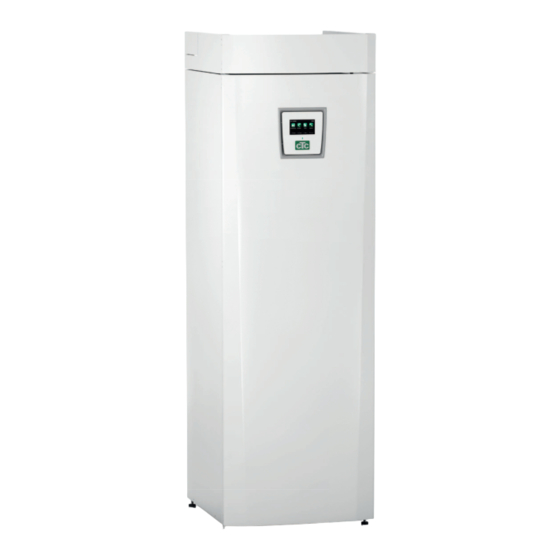
- Page 1 162 105 80-1 2017-02-14 Providing sustainable energy solutions worldwide Installation and Maintenance Manual CTC GSi-12 (BE) Modulating ground source heat pump 400V 3N~ IMPORTANT READ CAREFULLY BEFORE USE KEEP FOR FUTURE REFERENCE...
- Page 2 Removing the cooling module GSi 12 • Any work done on the product’s cooling system should be done by authorised personnel only. • Close the safety switch before doing any work on the product. 1. Disconnect the cooling module’s power cable connector and hoses. 2.
- Page 3 Installation and Maintenance Manual 162 105 80-1 2017-02-14 CTC GSi-12 (BE) Modulating ground source heat pump 400V 3N~...
-
Page 4: Table Of Contents
General Information Table of Contents Important to remember! _____________________________________________ Your home’s heating installation ________________________________ 10. Menu overview ___________________________________________________ Technical data ____________________________________________________ 11. Detailed menu descriptions ______________________________ The envelope CTC GSi-12 (BE) ________________________ 11.1 Start menu ___________________________________________________ Design ________________________________________________________________ 11.2 Room temperature _________________________________________ Parameter list _____________________________________________________... - Page 5 CTC GSi-12 (BE)
-
Page 6: Important To Remember
Important to remember! Check the following in particular on delivery and installation: • The product must be transported and stored in an upright position. • Remove the packaging and check before installation that the product has not been damaged in transit. Report any transport damage to the carrier. - Page 7 Congratulations on your new product You have just bought a CTC GSi-12 (BE), which we heating block, which maximises the temperature hope you will be very pleased with. In the following supplied to the floor circuits. Using the integrated pages you can read about how to operate and maintain night reduction function, you can set and change the your heat pump.
- Page 8 Safety instructions Turn off the power with an omnipolar switch before doing any work on the product. The product must be connected to protective earth. The product is classified as IPX1. The product must not be rinsed with water. When handling the product with a hoist ring or similar device, make sure that the lifting equipment, eyebolts and other parts are not damaged.
-
Page 9: Your Home's Heating Installation
Your home’s heating installation The House Heating Curve The heating curve is the central part of the product’s control system. It is the heating curve which determines the compensated flow temperature requirements for your property dependent upon the outdoor temperatures. It is important that the heating curve is correctly adjusted, so that you achieve the best operation and economy possible. - Page 10 Adjusting the heating curve The method described below can be used to adjust the heating curve correctly. Adjustment if it is too cold indoors • If the outdoor temperature is lower than 0 degrees: Increase the Inclination value by a couple of degrees. Wait 24 hours to see if any further adjustment is required.
- Page 11 Examples of Heating Curves You can see in the diagram below how the heating curve changes with different Inclination settings. The gradient of the curve shows the temperatures that the radiators require at different outdoor temperatures. Primary Flow Temperature Curve Inclination The inclination value which is set is the primary flow temperature when the outside temperature is –15 °C.
- Page 12 Summer-time operation Primary Flow Temperature Heating All properties have internal heat gains (lamps, oven, ºC switched body heat, etc.), which means that the heating can be Heating up switched off when the outdoor temperature is lower than the desired room temperature. The better insulated the house is, the earlier the heating from the heat pump can be switched off.
-
Page 13: Technical Data
Technical data Electrical data Electrical data 400V 3N~ 50 Hz Rated power Max starting current Immersion heater Min fuse size Max. operating current Compressor IP class IPX1 Operational data for heat pump Max output from compressor 11.8 Output from compressor @ 0/35 | 0/45 | 0/55 6.17 I 5.64 I 5.40 @50 rps Input power... - Page 14 Technical data Brine system Water volume (V) Brine system min/max temp (TS) °C -5 / +20 Brine system min/max pressure (PS) 0.2/3.0 Brine system min flow 0.29 Brine system nominal flow, ∆t=3 K @50rps 0.39 Brine pump Grundfos UPMXL GEO 25-125 Pump capacity See diagram in chapter Pipe installation DHW system...
-
Page 15: The Envelope Ctc Gsi-12 (Be)
The envelope CTC GSi-12 (BE) The envelope is based on standard rating running conditions, and may deviate at actual installation. tci = temperature cold side inlet.(t = temperatur brine in) °C °C Water flow temp ( °C Water return temp ( °C The envelope is based on standard rating running CTC GSi-12 (BE) - Page 16 1. Cold water Ø22 2. Hot water Ø22 3. Radiator return Ø22 4. Primary low Ø22 5. Expansion connection/ Lifting sleeve G 3/4” CTC GSi-12 (BE)
-
Page 17: Design
2. Design The picture below shows the fundamental construction of the heat pump. The energy in the bore hole (bedrock) or ground is drawn up by the cooling system. The compressor then increases the temperature to a usable level. Afterwards it releases the energy for the heating system and hot water. Tap water connections The property’s tap water connections are connected... -
Page 18: Parameter List
3. Parameter list Heating circuit Factory User value DHW tank Factory User value settings settings Max primary l ow ºC Stop temp °C Min primary l ow ºC Start/stop diff upper ºC Heating, mode Auto Max time DHW Heating, mode, ext DHW ºC Heating off, out ºC Smart low price ºC... - Page 19 List of solar panel parameters This page is only for Solar panels Factory User value solar panels settings. settings Charge start diff temp °C Charge stop diff temp °C Charge pump min % Sensor test active -Test/Paus, min 4 / 30 -Winter break No Nov- Feb Prioritize charging...
-
Page 20: Installation
Installation 4. Installation This section is aimed at anyone responsible for one or more of the installations required to ensure that the product works the way the property The product must owner wants. be transported and stored in an upright Take your time going through functions and settings with the property owner position. -
Page 21: Control Functions, Std. And With Expansion Card
Control functions, std. and with expansion card The product is supplied from the factory with control functions according to “Basic functions” below. Supplementing with the expansion card accessory (A3) adds solar control and its variants as well as bore hole recharging and various tanks. Hot water circulation and pool control are also added. -
Page 22: Pipe Installation
5. Pipe installation The installation must be carried out in accordance with current standards and regulations. Refer to MIS 3005 and associated building regs Part L, F & G. The product must be connected to an expansion vessel in an open or closed system. - Page 23 5.1.1 Filling valve, heating circuit Fit a filling valve between the cold water connection and the heating circuit’s return line, or between the cold water pipe and the expansion pipe. 5.1.2 Non-return valve Fit the non-return valve to the incoming cold water connection. 5.1.3 Shut-off valves It is important to fit a shut-off valve (94) to the primary flow.
- Page 24 5.1.6 Expansion vessel connection (accessory) The heat pump is best connected to a closed expansion vessel. The heat pump is ready to be fitted to an 18 l closed expansion vessel, positioned on top of the product. The expansion vessel with the required hoose and angle connection is available as an accessory.
- Page 25 5.1.8 Pressure drop graph CTC GSi-12 (BE) - warm side Δp l/min GSi-12 pressure drop warm side Δp 5.1.9 Heat medium pump (Charge pump G11) Yonos Para RS 25/7,5 PWM1 130 l/min Ämnes nr Wilo-nr: 4526836 Distr till/Antal Tol.system Ersätter Ytjämnhet RA 586877301 art.
- Page 26 5.1.10 Electric shut-off valve (Y47) If you have two heating circuits and wish to have background heating in heating circuit 2 and the heat off during the summer in heating circuit 1, you can use an electric shut-off valve (Y47). Terminal block A13 is powered during the heating season and not powered in the summer.
- Page 27 5.1.12 External heat source (EHS) This function is used to connect additional heat sources to the heating circuit, e.g. water-jacketed stove, solar heat. The heat from the external heat source is diverted into the system when the set temperature in the external tank is reached, and is at least 5ºC higher than the setpoint.
- Page 28 5.1.13 Diff thermostat function The diff thermostat function is used if you want to transfer heat from a tank with the sensor (B46) to a tank with the sensor (B47). The function compares the temperatures in the tanks and when it is warmer in the first tank (B46), charging starts to the second tank (B47).
- Page 29 5.1.15 Solar (accessory) Solar heat is connected to the system through an external heat source tank (EHS-tank). The number of solar panels which can be connected depends on the volume of water in the product/tanks to which the solar panels are to be connected. System 1 System 1 is a system structure with solar heat going directly to an external heat source tank (EHS-tank).
- Page 30 System 2 System 2 is a system structure with solar heat connected to an external heat source tank (EHS-tank) and an extra buffer tank (CTC EcoTank for example). The system allows for a larger solar collector surface since it carries a greater volume of water.
- Page 31 System 3 System 3 is a system structure with an extra volume called 03; this can be a large extra tank or a pool. The greater the volume of water, the greater the solar collector surface. Solar heat is connected to an external heat source tank (EHS-tank) and an extra buffer tank (CTC EcoTank for example).
- Page 32 5.1.16 Schematic diagram (overall) CTC GSi-12 (BE)
-
Page 33: Connecting The Brine System
6. Connecting the brine system The brine system, i.e. the ground collector loop, must be assembled and connected by a qualified tradesman in accordance with current regulations and design guidelines. Care must be taken to ensure that no dirt gets on the collector hoses, which must be washed clean before being connected. - Page 34 6.1.1 Connection options Left-side installation Right-side installation • Use the rear through-hole • Use the front through-hole • Fit the “brine out” hose • Push in the “brine out” hose from the side • Pull out the hose from the front while pushing •...
- Page 35 6.1.2 Valves Ft the valves as shown in the schematic diagram on the next page. To facilitate servicing of the cooling unit, shut-off valves should be fitted to both the incoming and outgoing connections. Fit bifurcated valves so that it is possible to fill and bleed the collector circuit later on.
-
Page 36: Brine System Schematic Diagram
Brine system schematic diagram Level/expansion vessel Filler manifold Shut-off valves Filter 100 External filling pump 101 Mixing vessel 102 Brine pump 103 Evaporator 104 Safety valve 3 bar The diagram shows the main connection for the brine system. The filling equipment is represented by the parts displayed with dashes. - Page 37 6.2.1 Brine Check the dirt filter The brine circulates in a closed system. The fluid consists of water and after bleeding has antifreeze solution. Sentinel R500 & R500C are recommended for use in the been completed. brine circuit. The glycol is mixed at a concentration of slightly less than 30%, which is equivalent to fire risk class 2b and a freezing point of around -15°C.
-
Page 38: Brine Pump (G20)
6.3.1 Pressure drop graph CTC GSi-12 (BE) - cold side Δp ≤ l/min GSi-12 pressure drop cold side Pressure drop, brine circuit side Brine pump (G20) The circulation pumps in CTCs products are of the energy efi ciency class A. Electrical data, 1 x 230 V, 50 Hz UPMXL GEO 25-125 180 PWM, 1 x 230 V, 50/60 Hz [kPa]... -
Page 39: Electrical Installation
7. Electrical installation Safety information The following safety instructions must be observed when handling, installing and using the product: Turn off the power with an omnipolar switch before doing any work on the product. • The product is classified as IPX1. The product must not be rinsed with water. -
Page 40: Sensor Connection
Sensor connection Sensors should be connected on the top cover, behind the product’s top trim. Sensor terminal block Connect the sensors on the top cover of the product, behind the top trim. Connection of outdoor sensor (B15) The outdoor sensor is connected to G11–G12 on the sensor terminal block. The sensor should be set up on the house’s northwest or north side, so that it is not exposed to morning and evening sun. -
Page 41: Check Connected Sensors
Check connected sensors If any sensor is incorrectly connected, a message will appear on the display, e.g. “Alarm sensor out”. If several sensors are incorrectly connected, the different alarms are displayed on different rows. If no alarm is displayed, the sensors are connected correctly. Pressure/level switch The pressure/level switch is connected to blocks G73 and G74 and then defined under the Advanced/Define system/Def Heat pump menu. -
Page 42: Heating Circuit 2 (Or Cooling)
Heating circuit 2 (or cooling) Primary flow sensor 2 (B2) is connected to terminal blocks G15–G16 on the sensor terminal block. Mixing valve 2 (Y2) is connected to: Black cable Open Terminal block A15 Brown cable Close Terminal block A16 Blue cable Zero Terminal block A17... -
Page 43: Pool (Accessory)
Pool (accessory) Connect the sensor (B50) which measures the pool temperature to expansion card (A3) terminal block X3: 15-16. Connect the circulation pump (G51) to expansion card (A3) as below: Phase: brown Terminal block X: 33 Earth: yellow/green Terminal block X: 34 Zero: blue Terminal block X: 35... -
Page 44: Solar (Accessory)
Solar (accessory) Pump solar panel (G30) PWM 230 V 1N~ Circulation pump G30 is powered separately (not from this unit). The PWM control signal is connected to the following terminal blocks: Expansion card (A3) X5: Note the cable colours! PWM+: white Terminal block X5: 1 GND: brown... -
Page 45: Current Sensor Connection (Accessory)
Valve bedrock (Y31) 230 V 1N~ Diverting valve Y31 is connected to pump G31 at the following terminal blocks: Expansion card X6: Control voltage: black Terminal block X6:8 Phase: brown Terminal block X6:9 Zero: blue Terminal block X6:11 7.10 Current sensor connection (accessory) The current sensors are connected at G37–G40 on the sensor terminal block. -
Page 46: Tank Schematic Diagram (A2)
7.11 Tank schematic diagram (A2) Power supply Heat pump CTC GSi-12 (BE) - Page 47 CTC GSi-12 (BE)
-
Page 48: Hp Cooling Module Schematic Diagram (A5)
7.12 HP cooling module schematic diagram (A5) CTC GSi-12 (BE) - Page 49 CTC GSi-12 (BE)
-
Page 50: Expansion Card (A3) Schematic Diagram
7.13 Expansion card (A3) schematic diagram (accessory) a) CTC EcoZenith i350 CTC GSi-12 (BE) - Page 51 B102 CTC GSi-12 (BE)
-
Page 52: Parts List
7.14 Parts list Display Relay/main card Circulation pump 2 Expansion card Charge pump for DHW HP control card Charge pump HP1 Driver Brine pump Circulation pump, solar panel Primary flow sensor 2 NTC 22 Pump, bedrock (recharging bore hole) Sensor, hot water tank NTC 22 Pump, plate heat exchanger –... -
Page 53: Resistances For Sensors
7.15 Resistances for sensors NTC 150 NTC 22 kΩ Temperature °C Temperature °C Outdoor sensor Resistance Ω Resistance Ω 1027 1167 1330 1522 1746 2010 2320 2690 3130 3650 4280 5045 5960 7080 8450 10130 12200 1115 14770 1443 18000 1883 22000 2478... -
Page 54: First Start
8. First start When the heat pump is delivered, the compressor is blocked to avoid it being unintentionally started. The heat pump can be installed and started before the brine circuit is put into operation. The heat pump can also be started without a room sensor being fitted as the curve which has been set then regulates the heating. -
Page 55: Operation And Maintenance
9. Operation and Maintenance When the installer has installed your new heat pump, you should check along with the installer that the system is in perfect operating condition. Let the installer show you where the switches, controls and fuses are so that you know how the system works and how it should be maintained. -
Page 56: Important Information On Air Bleeding
Important information on air bleeding For the product to work as intended, the system must be fully bled. Important! The water must be circulated in the various It is extremely important that a basic bleeding of the subsystems, the radiator systems, the heat pump product is carried out systematically and carefully. - Page 57 CTC GSi-12 (BE)
-
Page 58: Menu Overview
10. Menu overview Night reduction heat circ. Start menu CTC GSi 12 (BE) CTC GSi 12 Monday 09:35 Weekly program Day by day Monday 22 - 24 -- - -- 00 - 06 -- - -- Tuesday -- - -- -- - -- Wednesday -- - --... - Page 59 Installer Time Language Stored oper data Total operation time h: 14196 Max primary flow °C: Electric Heating kWh Settings Compressor: Heating circuit 1 Heating circuit 2 Total operation time 1540 Heat pump Electric heater DHW-tank Communication Cooling Solar panels Compressor Diff thermostat function Pool External heat source Compressor...
-
Page 60: Detailed Menu Descriptions
11. Detailed menu descriptions Start menu All the settings can be configured directly on screen CTC GSi 12 (BE) CTC GSi 12 Monday 09:35 using the well-structured control panel. The large icons operate as buttons on the touch display. Operational and temperature information is also displayed here. -
Page 61: Room Temperature
11.2 Room temperature Room temp. Heating circuit 1 This is used to set the desired room temperature. Use the plus and minus buttons to set the temperature you want. The “setpoint” temperature is given in brackets. You can see the current value next to the brackets. If two heating circuits are installed, the values for both Night reduction Holiday... - Page 62 11.2.3 Night reduction temperature Night reduction heat circ. Weekly program Day by day Monday 22 - 24 -- - -- 00 - 06 -- - -- Tuesday -- - -- -- - -- Wednesday You use this menu to activate and set a reduction in Thursday -- - -- -- - --...
-
Page 63: Dhw
11.3 DHW Extra Hot water hours You use this to set the DHW comfort level you want and Temperature temporary extra DHW. Normal Temperature You set the values for this option which apply to the heat pump’s normal operation. There are three modes: Weekly schedule Economic –... -
Page 64: Operation
11.4 Operation Operation data system This menu displays current temperatures and the operational data for your heating system. The screen shows the incoming and outgoing temperatures from the heat pump. Brine in At the top left of the heat pump (2°C) the brine’s current temperature is shown from the collector to the heat Information pump. - Page 65 11.4.1 Operation data CTC GSi-12 (BE) Operation data Status DHW tank °C 49/ 45 (55) DHW ºC 54 (50) This menu displays current temperatures and Stored oper data Degree minute -1000 Electric power kW operational data. The first figure is the actual operational Current L1/L2/L3 value, with the value in brackets being the setpoint Diff func.
- Page 66 Pool ºC 19 (22) Displays pool temperature and setpoint (in brackets). DHW circulation Off/On Shows whether the DHW circulation pump is turned on. External heat source Off/On /55 Shows whether the external heat source is supplying heat. Also displays the temperature in the external tank. 11.4.2 Stored operation data Stored oper data Total operation time h:...
- Page 67 11.4.3 Operation data, compressor Compressor This menu is intended for servicing and advanced Compressor troubleshooting. Charge pump On 47% Brine pump HP in/out °C 35.5 / 42.3 Compressor (On/Off /65 rps) Shows whether the compressor is operating or not, as well as showing the compressor speed in rps (revolutions per second).
- Page 68 11.4.4 Heating circuit Heating Circuit Primary flow 1 ºC 37 (38) Return flow ºC Radiator pump Primary flow °C Primary flow 2ºC 37 (38) Shows the temperature supplied to the system’s Radiator pump 2 Mixing valve 2 radiators, along with the temperature which the system is trying to achieve.
- Page 69 11.4.6 Operation data, solar panels Operation solar panels This menu displays current temperatures and operating Status: Heating Charging EHS-tank data for your solar collectors. The menu is only shown if Solarpanel In/Out °C 65/70 EHS-tank ºC (B47) solar collectors are defined. EcoTank (B41)(B42) °C 72 / 50 X-volym (B41)(B42)°C...
- Page 70 Energy output / 24 kWh Shows the amount of energy absorbed in the last 24 hours. If heat is taken from the tanks (e.g. if a panel is being protected against frost), negative energy is calculated. During bore hole recharging no useful energy is calculated.
-
Page 71: Installer
11.5 Installer Installer This menu contains four sub-menus. Time/Language, Settings, Define system and Service. Time/Language Settings Define system Service Time/Language includes time and language settings for your CTC GSi-12 (BE). Software display PCB: 20120205 Settings are used both by the installer and users for Software HP PCB: 20120125 installing the system. - Page 72 11.5.2 Settings Settings Heating circuit 1 Heating circuit 2 Heat pump Electric heater This menu is used to set the parameters for your DHW-tank Communication home’s heating requirements. It is important that this Cooling basic setting is right for your home. Values which are Solar panels Diff thermostat function set incorrectly may mean that your property is not warm...
- Page 73 Heating off, out 18 (10 to 30) Outdoor temperature limit at which the house no longer There is no radiator pump requires heating. The radiator pump (G1/G2) stops. The in heating circuit 1. Instead, radiator pump (G2) is activated daily for a short period “Heating, mode”...
- Page 74 Smart over capacity ºC 2 (Off/1..5) Setting to increase adjustment at over capacity energy price, via Smart Grid. Find out more in the section entitled “Smart Grid”. Max time heating 20 (10 to 120) This is the maximum time spent by the heat pump charging the heating circuit if heat is needed in the DHW tank.
- Page 75 Drying period mode Off (Off/1/2/3) Floor drying function for newly-built properties. The function limits the calculation of primary flow temperature (setpoint) for “Your home’s heating settings” to the schedule below. Mode 1 Floor drying function for 8 days. #1. The (setpoint) for the heating circuit is set to 25ºC for 4 days.
-
Page 76: Heat Pump
11.6 Heat pump Heat pump Compressor Permitted/Blocked Compressor: Permitted Brine pump on Auto The product is supplied with a blocked compressor. Tariff HP Smart block HP Since the compressor is blocked, the product operates Start at degree minute like an electric boiler with full functionality. Permitted Max RPS Max RPS silent mode means that the compressor is allowed to operate. -
Page 77: Electric Heater
11.7 Electric heater Electric heater Max el. heater kW 1.2 (0/1.2) Max el. heater kW Max el. heater DHW kW Maximum permitted output from electric immersion Start at degree minute -500 heater. Diff step, degree minute Main fuse A Max el. heater DHW kW 0 (0/1.2) Tariff EL Smart block immersion... -
Page 78: Dhw Tank
11.8 DHW tank DHW tank Stop temp °C 55 (40 to 65) Stop temp °C Start/stop diff upper ºC At this temperature charging of the DHW tank stops. Max time DHW DHW ºC Start/stop diff upper °C 5 (3 to 10) Charge pump % Smart low price ºC The temperature difference between stop and start... -
Page 79: Communication
11.9 Communication These settings are activated for the accessory’s superior systems and are not used in normal operation. They are not described in these instructions. 11.10 Cooling Cooling Cooling is adjusted using primary flow sensor 2 (B2), Condense Secured? which means that heating circuit 2 and cooling cannot Room temp cooling 18.0 Smart low price ºC... -
Page 80: Solar Panels (Accessories)
11.11 Solar panels Set solar panels (accessories) Solar basic settings Panel protection The settings needed for the solar heating system to EHS-tank X-volume function optimally are entered here. It is important that Recharging of bedrock this default setting is adjusted for your heating system. Charging EHS-tank Incorrectly set values may lead to the intended energy saving being lower. - Page 81 Prioritise charging of: EHS/ X-volume This is where you indicate whether the tank for the external heat source or the X-volume (acc. tank) should be prioritised when charging (shown only if alternate charging has been defined). Flow l/min 6.0 (0.1 to 50.0) The flow circulating through the solar collectors should be indicated here.
- Page 82 Antifreeze protection panel No (No/Yes) Winter time; at extremely cold outdoor temperatures there is a risk of the panels freezing (despite antifreeze fluid). The function to take heat from the tank to the panel is activated here. -Active when panel temp °C -25 (-30 to -7) This is where the temperature in the solar collector at which the frost protection starts is indicated.
- Page 83 11.11.5 Settings X-volume X-volume Settings applicable when X-volume is activated. Charge temperature °C This is also called system 3. Maximum tank temp °C Charge temperature °C 60 (10 to 95) Setting for the maximum permitted temperature in the X-volume. Charging stops once the set temperature has been reached.
-
Page 84: Diff Thermostat Function
11.11.7 Charging EHS-tank Charging EHS-tank This function concerns charging conditions between Charge start diff temp °C EcoTank and EHS-tank in solar system 2. Charge stop diff temp °C This function CANNOT be combined with the “Diff Charge tank temp °C thermostat function”. -
Page 85: Pool (Accessory)
11.13 Pool (accessory) Pool Pool temp ºC 22 (5 to 58) Pool temp °C Pool diff °C The pool temperature is set in this menu. Max time Pool Charge pump % Pool diff ºC 1.0 (0.2 to 5.0) Smart low price ºC Smart overcapacity ºC The permitted difference between the start and stop temperature in the pool is specified here. -
Page 86: Deine System
11.15 Defi ne system Define system Heating circuit 1 Heating circuit 2 Heatpump You can use this option to define your heating circuit CTC SMS Cooling and how it is controlled, with or without a room sensor. Solar panels Diff thermostat function The heat pump’s flow switch is defined. - Page 87 11.15.1 Defi ne SMS (accessory) System Def CTC SMS This is for defining whether SMS control is installed Activate (accessory). Level of signal Phone Number 1 +46712345678 Activate Yes (Yes/No) Phone Number 2 ----------------- If “Yes”, the menus below will be displayed. Hardware Version Software Version Level of signal...
- Page 88 11.15.4 Defi ne Diff thermostat function (accessory) Specify here whether the diff thermostat function is to be used in the system. Diff thermostat function No (No/Yes) 11.15.5 Defi ne Pool (accessory) Specify here whether Pool should be connected to the heating circuit.
-
Page 89: Deine Remote Control
11.16 Defi ne remote control The remote control function in CTC's products provides a wide range of opportunities to adjust the heating externally. There are four programmable inputs that can activate the following functions: • Heat pump tariff • Flow/level switch •... - Page 90 Activate/select function. Heating circuit When an input is assigned, the function must Max primary flow ºC be activated or set in the Settings menu. Min primary flow ºC Heating, mode Auto Heating, mode, ext In the example with remote controlled “Heating, Heating off, out ºC Heating off, time ext.
-
Page 91: Smart Grid
Flow/level switch In some cases, extra protection is required due to local requirements or provisions. For example, the requirement in some areas is for the system to be installed within a water catchment area. The pressure/level switch is defined in the Installer/Define system/Def. heat pump menu. If there is a leak, the compressor and brine pump stop and the Flow/level switch alarm appears on the display. - Page 92 In each function that can be controlled there is a choice of temperature Smart low price ºC 1 (Off, 1-5 ) change for low price mode and overcapacity mode. Smart overcap. ºC 2 (Off, 1-5 ) Example: factory-set low price 1°C increase* in temperature. Example: factory-set overcapacity 2°C increase* in temperature.
- Page 93 Blocking mode: (A: Closed, B: Open). • The heat pump and immersion heater can be blocked in accordance with the settings in heat pump and immersion heater. • Smart blocking HP No (Yes/No) Blocks heat pump Installer/Settings/Heat pump • Smart blocking immersion heater No (Yes/No) Blocks immersion heater Installer/Settings/Electric heater...
-
Page 94: Service
11.19 Service Service Function test Alarm log Factory settings coded Quick start compressor. Software update, USB Write log to USB NB: This menu is intended for the Control current sensors Re-installation installer only. 11.19.1 Function test Function test This menu is intended to test the function of the Heating circuit Heat pump various components in the product. - Page 95 11.19.3 Test Heat pump Test Heat pump Function test carried out on the heat pump. HP Compr. HP Compr. HP Brine p HP Charge p Compressor On/Off. This is where the function test is carried out on the compressor. The brine pump and charge pump are also operating so that the compressor will not trigger its pressure switches.
- Page 96 11.19.5 Test Solar (accessory) Function test This function will only work if an expansion card Solar panel pump (G30) accessory is connected to the product. Heatexchanger pump (G32) Bedrock (Y31/G31) Tank Solar panel pump (G30) % 0 (0 to 100) Pump EHS (G46) Valves 2 tanks (Y30) EHS-tank...
- Page 97 11.19.6 Test Diff thermostat/EHS Pump EHS (G46) (On/Off) Charge pump function test. Mixing valve (Y41) (-/Open/Close) Temperatures This displays current temperatures. EHS-tank ºC (B47) Diff thermostat ºC (B46) 11.19.7 Test Pool (accessory) Pool pump/Valve (G51)/(Y50) (On/Off) Test of pool pump and valve. Temperatures This displays current temperatures.
- Page 98 Factory settings coded NB: Only an authorised service engineer is allowed to log into the Factory settings coded option. Severe operational problems and faults may occur affecting the product if values are amended without authorisation. Note that in such cases the warranty terms do not apply.
-
Page 99: Troubleshooting/Appropriate Measures
12. Troubleshooting/appropriate measures The heat pump is designed to provide reliable operation and high levels of comfort, and to have a long service life. Various tips are given below which may be helpful and guide you in the event of an operational malfunction. If a fault occurs, you should always contact the installer who installed your unit. - Page 100 Current monitor The heat pump has an integrated current monitor. If the system is fitted with a current sensor, the property’s main fuses are continuously monitored to ensure they are not overloaded. If this should happen, electric stages are disconnected from the heat pump. The heat pump may be restricted where high heating requirement levels are combined with, for example, single-phase engine heaters, cookers, washing machines or tumble dryers.
-
Page 101: Information Messages
12.1 Information messages Information messages are displayed when appropriate and are intended to inform users about various operational situations. Start delay Start delay The compressor is not allowed to start too quickly when it has stopped. The delay is usually at least 10 minutes. Heating off, radiator sys Shows that the product is operating in summer-time mode when only hot water is required, not heating. -
Page 102: Alarm Texts
12.2 Alarm texts Alarm: Wrong phase order compressor Reset alarm If a fault occurs with a sensor, for instance, an alarm is triggered. A message appears on the display with information about the fault. You reset the alarm by pressing the Reset alarm button on the display. If several alarms are triggered, they are displayed one after the other. - Page 103 Alarm text Description Max. thermostat If the heat pump has been stored in an extremely cold place, the max. thermostat may have been triggered. You reset it by pressing in the button on the electrical switchboard behind the front panel. Always check on installation that the max.
- Page 106 CTC GSi-12 (BE)
- Page 107 CTC GSi-12 (BE)
- Page 108 162 105 80-1 2017-02-14 Enertech AB. PO Box 309 SE-341 26 Ljungby Sweden. www.ctc.se, www.ctc-heating.com...
Need help?
Do you have a question about the GSi-12 BE and is the answer not in the manual?
Questions and answers