Table of Contents
Advertisement
Quick Links
Advertisement
Table of Contents

Related Manuals for CTC Union GS 600


Summary of Contents for CTC Union GS 600
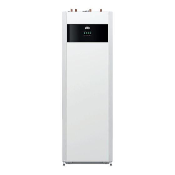
- Page 1 Installation and Maintenance Manual CTC GS 600 Modulating ground source heat pump Model 606 / 608 400V 3N~/ 230V 1N~/ 230V 3N~ Important! • Read carefully before use, keep for future reference. • Translation of the original instructions. 162 505 70-5 CR00683 2023-06-20...
-
Page 2: Table Of Contents
Table of contents Safety instructions ...............6 Installation Communication ..........64 11.1 Install ethernet cable ..............65 Important to remember! ............7 11.2 Remote - Screen Mirroring ............66 Transportation ................7 11.3 myUplink - App ................66 Positioning ..................7 Recycling ..................7 First start ................67 After commissioning .............. - Page 3 Removing the cooling module • Any work on the product’s cooling system should be carried out by authorised personnel only. • Close the safety switch before doing any work on the product. Disconnect the cooling module’s power Attach the two carrying handles to the cable connector and hoses.
- Page 4 Important! Information on air bleeding For the product to work as intended, the system must be fully bled. It is extremely important that a basic bleeding of the product is carried out systematically and carefully. Bleeding devices must be fitted to the system’s natural high points. A basic bleeding of the hot water tank can be carried out upon installation by releasing the safety valve, which must be fitted to the top of the product.
- Page 5 Congratulations on your new product You have just purchased a CTC GS 600, with which we CTC GS has a control system which: hope you will be very pleased. Read about how you can • monitors all heat pump functions.
-
Page 6: Safety Instructions
Safety instructions Turn off the power with an omnipolar switch before doing any work on the product. The product must be connected to protective earth. The product is classified as IPX1. The product must not be rinsed with water. When handling the product with a hoist ring or similar device, make sure that the lifting equipment, eyebolts and other parts are not damaged. -
Page 7: Important To Remember
Important to remember! Check the following points at the time of delivery and installation: • Remember to leave a service area of at least 1 Transportation metre in front of the product. The product must not be placed below floor level Transport the unit to the installation site before removing •... -
Page 8: Installation
Installation This section is aimed at anyone responsible for one or more of the installations The product must be required to ensure that the product works the way the property owner wants. transported and stored in Take your time going through functions and settings with the property owner an upright position. -
Page 9: Control Functions (Std.) And With Expansion Card
Control functions (std.) and with Expansion Card The product is supplied from the factory with control functions according to "Basic functions" below. Supplementing with the expansion card accessory (A3) adds solar control and its variants as well as bore hole recharging and various tanks. In addition, DHW circulation and pool control are also included. -
Page 10: Your Home's Heating Installation
Your home's heating installation The House Heating Curve The heating curve is the central part of the product’s control system. It is the heating curve which determines For more information on how to set the the compensated flow temperature requirements for your heating curve, see section ”Heating curve”... - Page 11 Appropriate Default Values During installation you can seldom achieve a precise setting for the heating curve instantly. In this case, the values given below may provide a good starting point. Radiators with small heat-emission surfaces require a higher primary flow temperature. You can adjust the gradient (heating curve gradient) for your heating system under the "Installer / Settings ...
- Page 12 Examples of Heating Curves You can see in the diagram below how the heating curve changes with different Inclination settings. The gradient of the curve shows the temperatures that the radiators require at different outdoor temperatures. Curve Inclination Primary Flow Temperature The inclination value which is set is the primary flow temperature when the outside temperature is –15 °C.
- Page 13 Heating Summer season Primary Flow Temperature switched off ºC All properties have internal heat gains (lamps, oven, Heating up body heat, etc.), which means that the heating can be switched off when the outdoor temperature is lower than the desired room temperature. The better insulated the house is, the earlier the heating from the heat pump can be switched off.
-
Page 14: Technical Data
Technical data Electrical data GS 606 GS 608 CTC No. 589310001 589311001 589312001 589310002 589311002 589312002 Rated electrical data 3x400V 1x230V 3x230V 3x400V 1x230V 3x230V Rated power cooling module 2.75 2.75 3.45 3.45 Rated power input 11.5 8.25 9.75 12.7 8.95 10.45 Rated current cooling module... - Page 15 Brine system GS 606 GS 608 Water volume (V) 3.57 Brine system min/max temp (TS) °C -5 / +20 Brine system min/max pressure (PS) 0.2 / 3.0 Flow qc minimum B0/W35, ∆t = 6K 0.21 0.23 Flow qc nominal B0/W35, ∆t = 3K 0.33 0.46 Pump capacity...
-
Page 16: Operating Range Ctc Gs
Operating range CTC GS Operating range is based on normal operating conditions and may therefore be different in different installations. = temperature brine in) °C °C Primary flow temperature (t ) °C Return temperature (t T re ) °C T re... -
Page 17: Measurements
Measurements Erfoderlig reshöjd: 1940mm Cold water Ø22 Erfoderlig reshöjd: 1940mm Erfoderlig reshöjd: 1940mm DHW Ø22 Return Ø22 Primary flow Ø22 Expansion connection/ Lifting sleeve G 3/4" Bleed valve connection G 1/2"... -
Page 18: Design
Design The picture below shows the fundamental construction of the heat pump. The energy in the bore hole (bedrock) or ground is drawn up by the cooling system. The compressor then increases the temperature to a usable level. Afterwards it releases the energy for the heating circuit and DHW. Radiator connections The property’s heating system DHW connections... -
Page 19: Parameter List
Parameter list Factory setting Factory setting Heating circuit Electric heater Program Economy Max el. heater kW 5.8* Room temp change °C -2.0 Max el. heater DHW kW 0.0* Off delay, min Start at degree minute -500 Diff step, degree minute Program Comfort Room temp change °C Main fuse A... -
Page 20: Pipe Installation
Pipe installation The installation must be carried out in accordance with the applicable standards. The product must be connected to an expansion vessel in an open or closed system. Do not forget to flush the heating circuit clean before connecting. Apply all the installation settings based on the description in the section entitled "First start". -
Page 21: Schematic Diagram
Schematic diagram This shows the main connection between the heat pump and the property's heating and water supply system. Different installations and systems may look different, e.g. a one or two-pipe system, which means that the finished installation may be different. To find out about connecting the cold side, see the section entitled "Connecting the brine system". - Page 22 8.1.1 Filling valve, heating circuit Fit a filling valve between the cold water connection and the heating circuit’s return flow. 8.1.2 Non return valve Fit the non-return valve to the incoming cold water connection. NB: It is important to fit Shut-off valves 8.1.3 shut-off valves to both...
- Page 23 8.1.7 Expansion tank pre-pressure The pre-pressure in the expansion tank is calculated according to the height (H) between the highest-positioned radiator and the expansion tank. The pre-pressure must be checked/set before the system is filled with water. The system pressure must be set 0.3 bar higher than the pre-pressure in the expansion tank.
- Page 24 Pressure differential diagram - hot side 8.1.8 CTC GS 606 / 608 ∆p kPa GS 606 GS 608 10 l/min 20 l/min 25 l/min 30 l/min Varma sidan 8.1.9 Heat medium pump (G11) GS 608 / GS 612 25/7-130 PWM 20 l/min 25 l/min 32 l/min 38 l/min...
- Page 25 8.1.10 Electric shut-off valve Y47 If you have two heating circuits and wish to have background heating in heating circuit 2 and the heat off during the summer in heating circuit 1, you can use an electric shut-off valve (Y47). Terminal block A13 is powered during the heating season and not powered in the summer.
- Page 26 8.1.12 External heat source (EHS) This function is used to connect additional heat sources to the heating circuit, e.g. water-jacketed stove, solar heat. The heat from the external heat source is diverted into the system when the set temperature in the external tank is reached and is at least 5°C higher than the setpoint.
- Page 27 8.1.13 Diff thermostat function The diff thermostat function is used if you want to transfer heat from a tank with the sensor (B46) to a tank with the sensor (B47). Ensure a high flow on The function compares the temperatures in the tanks and, when it is warmer in the first tank (B46), charging starts to the second tank (B47).
- Page 28 8.1.15 Schematic diagram, passive cooling Alt. 1 common cooling/heating...
- Page 29 8.1.16 Schematic diagram, passive cooling Alt. 2 common cooling/heating...
- Page 30 8.1.17 Schematic diagram, passive cooling Alt. 3...
- Page 31 8.1.18 Solar heat (accessory) Solar heat is connected to the system through an external heat source tank (EHS- tank). The number of solar panels which can be connected depends on the volume of water in the product/tanks to which the solar panels are to be connected. System 1 System 1 is a system structure with solar heat going directly to an external heat source tank (EHS-tank).
- Page 32 System 2 System 2 is a system structure with solar heat connected to an external heat source tank (EHS tank) and an extra buffer tank (CTC EcoTank for example). The system allows for a larger solar collector surface since it carries a greater volume of water.
- Page 33 System 3 System 3 is a system structure with an extra volume called 03; this can be a large extra tank or a pool. The greater the volume of water, the greater the solar collector surface. Solar heat is connected to an external heat source tank (EHS-tank) and an extra buffer tank (CTC EcoTank for example).
- Page 34 8.1.19 Schematic diagram (complete diagram)
-
Page 35: Connecting The Brine System
Connecting the brine system The brine system, i.e. the ground collector loop, must be assembled and connected by a qualified tradesman in accordance with current regulations and design guidelines. Care must be taken to ensure that no dirt gets on the collector hoses, which must be washed clean before being connected. - Page 36 9.1.1 Connection options Left-side installation Right-side installation Use the rear through-hole. Use the rear through-hole. Push in the "brine out" pipe from the side. Fit the "brine out" pipe. Pull out the pipe from the front while Fit the "brine in" pipe. pushing in the pipe from the side.
- Page 37 9.1.2 Valves Ft the valves as shown in the schematic diagram on the next page. To facilitate servicing of the cooling unit, shut-off valves must be fitted to both the incoming and outgoing connections. Fit bifurcated valves so that it is possible to fill and bleed the collector circuit later on.
-
Page 38: Brine System Schematic Diagram
Brine system schematic diagram Level/expansion vessel Filler manifold Shut-off valves Filter External filling pump Mixing vessel Brine pump Evaporator Safety valve 3 bar The diagram shows the main connection for the brine system. The filling equipment is represented by the parts displayed with dashes. NB: Collector hoses must have a bleeding facility as air pockets can occur. - Page 39 9.2.4 Brine The brine circulates in a closed system. The fluid consists of water and antifreeze solution. Sentinel R500 & R500C are recommended for use in the Check the dirt filter brine circuit. The glycol is mixed at a concentration of slightly less than 30%, which is equivalent to fire risk class 2b and a freezing point of around –15°C.
- Page 40 10 l/min 20 l/min 25 l/min 30 l/min Varma sidan Pressure differential diagram - cold side 9.2.7 CTC GS 606 / 608 CTC EcoHeat 410-412/EcoPart 410-417 & CTC GSi 612 har pump 25-125 180. ∆p kPa 25/70-180, 1x230V, 50/60Hz GS 606 GS 608 ≤...
-
Page 41: Electrical Installation
10. Electrical installation Safety information Electrical installation must be performed in compliance with specific requirements in the national electrical safety standard. The following safety instructions must be observed when handling, installing and using the product: • Turn off the power with an omnipolar switch before doing any work on the product. -
Page 42: Sensor Connection
10.1 Sensor connection Sensor connection is carried out on top of the main product. Sensor terminal block Connection of outdoor sensor (B15) The outdoor sensor is connected to G11–G12 on the sensor terminal block. The sensor should be set up on the house’s northwest or north side, so that it is not exposed to morning and evening sun. -
Page 43: Checking Connected Sensors
10.2 Checking connected sensors If any sensor is incorrectly connected, a message will appear on the display, e.g. “Alarm: [E030] sensor out”. If several sensors are incorrectly connected, the different alarms are displayed on different rows. If no alarm is displayed, the sensors are connected correctly. 10.3 Pressure/level switch The pressure/level switch is connected to blocks G73 and G74 and then defined under the Installer/Define system/Def Heat pump menu. -
Page 44: Heating Circuit 2 (Alt. Passive Cooling)
10.6 Heating circuit 2 (alt. Passive cooling) Primary flow sensor 2 (B2) NTC 22k is connected to terminal blocks G15-G16 on the sensor terminal block. fit the primary flow sensor to the primary flow pipe, ideally after the circulation pump. The sensing part is towards the end of the sensor (see sketch). -
Page 45: Pool (Accessory)
10.7 Pool (accessory) Connect the sensor (B50) which measures the pool temperature at expansion card (A3) terminal block X3: 15-16. Connect the circulation pump (G51) to expansion card (A3) as below: Phase: brown Terminal block X7: 33 Earth: yellow/green Terminal block X7: 34 Zero: blue Terminal block X7: 35... -
Page 46: Solar Heat (Accessory)
10.11 Solar heat (accessory) Pump solar panel (G30) PWM 230V 1N~ Circulation pump G30 is powered separately (not from this unit). The PWM control signal is connected to the following terminal blocks: Expansion card (A3) X5: Note the cable colours! PWM+: white Terminal block X5: 1... -
Page 47: Current Sensor Connection (Accessory)
Valve bedrock (Y31) 230V 1N~ 3-way valve Y31 is connected with pump G31 at the following terminal blocks: Expansion card (A3) X6: Control voltage: black Terminal block X6:8 Phase: brown Terminal block X6:9 Zero: blue Terminal block X6:11 10.12 Current sensor connection (accessory) The current sensors are connected at G37–G40 on the sensor terminal block. -
Page 48: Electrical Diagram Tank (A2), 3X400V /1
10.13 Electrical diagram tank (A2), 3x400V /1. /3.C3 -X2:N /3.C3 #162 -X2:PE -PE Tank -PE Heater /1.F4 -F10:B1 /1.F4 -A2:A2 ALARM /1.F4 -F1:2 GNYE -X2:A36 /3.C3 #109 Θ -X22 /1.A3 -X22 /1.A3 -X22 /1.A3 230 V~ 12 V -X2:L1 /3.C2 TRANSDUCER -K23 -K25... -
Page 49: Flow Heater (E15), 3X400V /2
/1.B1 -X1:N (S1) 10.14 Flow heater (E15), 3x400V /2. /1.B1 /1.B1 -X1:N (S1) -X1:N (S1) /1.B1 /1.B1 -X1:N (S1) -X1:N (S1) 589366... -
Page 50: Terminal Block (X2), 3X400V /3
/1.E6 -A2:A15 #111 /1.E5 -A2:A16 #110 /1.E4 -A2:A36 #109 913145402 /1.A2 10.15 Terminal block (X2), 3x400V /3. -X1:N (S1) -W13 -W13 External 230V External 230V 913145403 /1.A2 -X1:PE #162 913145401 /1.C7 913145401 913145401 -A2:G42 #146 /1.E4 /1.E4 /1.C7 -A2:G43 #147 -F1:1 -F1:1 /1.C7... -
Page 51: Electrical Diagram Tank (A2), 1X230V /1
10.16 Electrical diagram tank (A2), 1x230V /1. /1.F4 -F1:1 #300 105,110 /2.B1 -X20, -X24 GNYE 13,16 /1.F4 -F1:2, -F10:B1 #255 ALARM GNYE -X2:A36 /3.C3 #109 Θ #306 -X22 /2.C3 /1.B2 230 V~ 12 V #255 -F10:A1 /3.C2 -X2:L1, -X10:L3 /1.A1 #300 TRANSDUCER -K23... -
Page 52: Flow Heater (E15), 1X230V /2
-X2:N /1.A3 -X10:PE #244 10.17 Flow heater (E15), 1x230V /2. /1.E4 #306 -A2:PE /1.C2 /1.C2 -X3:N -X3:N /3.C3 #162 -X2:PE /3.C3 /3.C3 -X2:N -X2:N /1.A3 /1.A3 -X10:PE #244 -X10:PE #244 /1.E4 /1.E4 #306 -A2:PE #306 -A2:PE /3.C3 /3.C3 #162 #162 -X2:PE -X2:PE 589367... -
Page 53: Terminal Block (X2), 1X230V /3
/1.E6 -A2:A15 #111 /1.E5 -A2:A16 #110 /1.E4 -A2:A36 #109 913145402 /2.C2 -X24 10.18 Terminal block (X2), 1x230V /3. -W13 -W13 External 230V External 230V 913145403 /2.C4 -X23 #162 913145401 /1.C7 913145401 913145401 -A2:G42 #146 /1.F4 /1.F4 /1.C7 -F1:1 #300 -F1:1 #300 -A2:G43 #147... -
Page 54: Electrical Diagram Tank (A2), 3X230V /1
10.19 Electrical diagram tank (A2), 3x230V /1. /2.A3 /1.F4 #244 -X22 -F1:1 #300 /2.C7 /2.D7 #326 -X11:5, -X11:6 13,16 /1.F4 -F1:2, -F10:B1 #255 ALARM GNYE -X2:A36 /3.C3 #109 Θ #306 /2.B3 -X22 /1.B2 230 V~ 12 V #255 -F10:A1 /3.C2 -X10:L3, -X2:L1 /1.A1 #300... -
Page 55: Flow Heater (E15), 3X230V /2
/1.B1 -X10:PE #244 10.20 Flow heater (E15), 3x230V /2. /1.E4 #306 -A2:PE /3.C3 #162 -X2:PE /1.B1 /1.B1 -X10:PE #244 -X10:PE #244 /1.E4 /1.E4 #306 -A2:PE #306 -A2:PE /3.C3 /3.C3 #162 #162 -X2:PE -X2:PE 589368... -
Page 56: Terminal Block (X2), 3X230V /3
/1.E6 -A2:A15 #111 /1.E5 -A2:A16 #110 /1.E4 -A2:A36 #109 913145402 /1.E2 10.21 Terminal block (X2), 3x230V /3. -F1:3 -W13 -W13 External 230V External 230V 913145403 /2.B4 -X23 #162 913145401 /1.C7 913145401 913145401 -A2:G42 #146 /1.F4 /1.F4 /1.C7 -F1:1 #300 -F1:1 #300 -A2:G43 #147... -
Page 57: Hp Cooling Module Schematic Diagram 3X400V (A5)
10.22 HP cooling module schematic diagram 3x400V (A5) Ω Ω Ω Ω Ω Ω Ω Ω Ω 586833... -
Page 58: Hp Cooling Module Schematic Diagram 1X230V / 3X230V (A5)
10.23 HP cooling module schematic diagram 1x230V / 3x230V (A5) 586661... -
Page 59: Expansion Card (Accessory) Schematic Diagram
10.24 Expansion card (accessory) schematic diagram 587205... - Page 60 B102...
-
Page 61: Component List
10.25 Component list Display Circulation pump 2 Relay/main card Circulation pump for DHW heat exchanger Expansion card Charge pump HP1 Gateway, SmartControl Brine pump Circulation pump, solar panel HP control card Primary flow sensor 2 Pump, bore hole recharging NTC 22 Sensor, DHW tank Pump, plate heat exchanger –... -
Page 62: Resistance Values For Sensor, Cooling Module
10.26 Resistance values for sensor, cooling module... -
Page 63: Resistance Values For Sensor, Other
10.27 Resistance values for sensor, other NTC 22 kΩ NTC 150 Temperature °C Temperature °C Resistance Ω Resistance Ω 1027 1167 1330 1522 1746 2010 2320 2690 3130 3650 4280 5045 5960 7080 8450 10130 12200 1115 14770 1443 18000 1883 22000 2478... -
Page 64: Installation Communication
11. Installation Communication Menu: "Installer/Define/Communication". The back of the display unit has 3 communication ports. Communication Display communication ports Port 1. RS485 port without galvanic protection. For external equipment, e.g. BMS, CTC AXS Define AXS: "Yes" permits BMS via the RS485 port and "CTC AXS"... -
Page 65: Install Ethernet Cable
11.1 Install ethernet cable In order to define and enable connection to the network and app, an ethernet cable must be connected as described below. 1. Pull out the magnetic strip. It is secured with magnets. 2. Open the ferrite from the packaging, clamp around the If difficult to remove, use a small screwdriver in the notch ethernet cable with the connector. -
Page 66: Remote - Screen Mirroring
11.2 Remote - Screen Mirroring • Connect the ethernet cable, see previous page. Installer/Define/Communication/Web – • Yes. Permits the product to connect with unencrypted web traffic on local area networks. Internet router and firewall required. Tablet/Smartphone/PC as a touchscreen for local area network "Installer/Define/Communication/Web"... -
Page 67: First Start
12. First start When the heat pump is delivered, the compressor is blocked to avoid it being unintentionally started. The heat pump can be installed and started before the brine circuit is put into operation. The heat pump can also be started without a fitted room sensor. The set curve will then regulate the heating. - Page 68 First start Switch on the power using the safety switch. The display will switch on. The heat pump now asks the following: Select the language and push OK. Confirm that the system is filled with water and press OK. Size of main fuse. Choose between 10 and 35 A. Specify the maximum electric heater power.
-
Page 69: Operation And Maintenance
13. Operation and Maintenance When the installer has installed your new heat pump, you should check along with the installer that the system is in perfect operating condition. Let the installer show you where the switches, controls and fuses are so that you know how the system works and how it should be maintained. -
Page 70: Detailed Menu Descriptions
14. Detailed menu descriptions All settings can be configured directly on screen using the straightforward control unit. The large icons function as buttons on the touch display. Operational and temperature information is also displayed here. You can easily access the different menus to find information on the operation or to set individual values. -
Page 71: Installation Wizard
14.2 Installation wizard When starting up the system and during reinstallation (refer to the "Installer /Service" chapter), a number of system options must be selected. The dialogue boxes which will then be displayed are described below. The values shown in the menu screenshots below are only examples. 1. -
Page 72: Heating/Cooling
14.3 Heating/Cooling In the menu "HC- Heating/Cooling" the following settings can be made: 14.3.1 Setpoint setting with room sensor Set the desired room temperature (set point) with the "minus" and "plus" buttons. In the example in the "HC1 Heating/Cooling" menu, the "Economy" programme and "Holiday mode"... - Page 73 14.3.2 Program Press the "Program" button and the heating program to be activated (Economy, Normal, Comfort or Custom). It is also possible to schedule the programmes. See chapter "Installer/Settings/Heating circuit/Program" for information on how to set temperature increases/ decreases and delay times for the programs. 14.3.3 Heating curve Press the heating curve symbol in the "HC1- Heating/ Menu ”HC1 Heating/Cooling / HC1 Program”...
- Page 74 14.3.5 Room temperature setting without room sensor If the room sensor is difficult to locate, if the underfloor heating system control has its own room sensor, or if you use a wood burning stove or fireplace, you can select Room sensor "No" in the "Installer/Define/Heating circuit"...
- Page 75 14.3.7 Night Reduction Temperature Night reduction means reducing the temperature indoors, via remote control or during scheduled periods. In the menu ”HC1 Night reduction” menu, the periods during the week for night temperature reduction can be scheduled. The ”Night reduction” icon in the ”Heating/Cooling” menu only appears if a ”Weekly Program”...
-
Page 76: Dhw
14.4 DHW This menu is used to set the hot water comfort level and "Extra DHW". Extra DHW The "Extra DHW" function can be activated here. When the function is activated (by setting the number of hours using the plus sign in the "Hot Water" menu), the heat pump immediately starts to produce extra DHW. -
Page 77: Weekly Program
14.6 Weekly program In a weekly program (designated "Program" in the display menus), the periods can be set for when a function should be active or inactive during the weekdays. The system does not allow certain functions to be active at the same time according to the same weekly program;... - Page 78 14.6.3 Editing a weekly program Go down to the first row and press "OK" to enable editing mode. Time Use the arrow keys to change the time (hours and minutes, respectively). Day by day Use the arrow keys (up arrow /down arrow) to mark active days in bold.
-
Page 79: Operation Data
14.7 Operation data NB: The operation values shown in the menu screenshots are only examples. Main menu page for "Operation Data". When the pumps are in operation, the pump icons also rotate on screen. Outside Temperature Measured temperature, outdoor sensor. Shows the room temperature for defined heating circuits (room sensors 1 Indoor temperature. - Page 80 14.7.1 Operation data, Control unit Click "Operation Data" in the start menu and then on the top part of the heat pump symbol to display the "Control Unit" menu. Status Current charging mode, see table below. DHW tank °C 49, 45 (55) Displays the hot water temperatures in the upper and lower parts of the tank.
- Page 81 14.7.2 Operation data, Heating circuit* Click on a heating circuit to see more detailed operation data in a new menu window. Mode Custom Shows the active DHW program. Status Heating Menu: "Operation data, heating circuit". The menu shows the current Shows the operational status of the heating circuit.
- Page 82 14.7.3 Operation data, Heat pump Status On, heating Shows the status of the heat pump. See the table below. Compressor 65rps Displays the compressor speed. Applies only to modulating heat pump CTC GSi 600. Charge pump Shows operating status of the charge pump ("On" or "Off") and the flow in percent.
- Page 83 14.7.4 Stored Operation data This menu shows cumulative operation values. The operation values shown in the menu screenshots are only examples. The historical operational info presented varies depending on the language choice. Total operation time h 3500 Shows the total time the product has been powered. Max primary flow °C Shows the highest temperature that has been supplied to Menu: "Operation data/Stored operation data".
- Page 84 14.7.5 Operation data, DHW Mode Comfort Shows the active DHW program. DHW tank °C 45, 55 (55) Shows the current temperature in the DHW tank and the setpoint (in brackets) for heat pump operation and during additional heat. DHW °C 45 (50) Displays the DHW temperature and setpoint (in brackets).
- Page 85 14.7.7 Operation Data, External heat source (EHS) This menu is displayed if an External Heat Source has been defined in the "Installer/Define/External Heat Source (EHS)" menu. System status Shows the various operational statuses of the system. Refer to the "Operation info/Control Unit" section. Status The status of the external heat source can be "Off"...
- Page 86 14.7.8 Operation data, El.prices This menu is displayed if ”El.prices” has been defined in the ”Installer/Define/Communication” menu. El.price mode High Indicates the current price category (”High”, ”Medium” or ”Low”). El.price/kWh SEK 7.5 Indicates the current electricity price in local currency. Menu: "Operation/El.prices".
-
Page 87: Display
Installer This menu contains four sub-menus: • Display • Settings Define • • Service For "System Information", click the "i" button in the lower right corner of the screen in the "Installer" menu. This displays the product serial number, MAC address, Menu: "Installer". - Page 88 14.8.2 Language Click a flag to select the language. The language selected is highlighted with a green square. To view more language options than those shown in the menu, scroll down the page, or press the down arrow key. 14.8.3 Country Click on the ”Country”...
-
Page 89: Settings
14.9 Settings This is used to set the parameters for your home’s heating requirements. It is important that this basic setting is right for your home. Values which are set incorrectly may mean that your property is not warm enough or that an unnecessarily large amount of energy is being used to heat your property. - Page 90 Program Press ”OK” on the ”Program” menu bar to make settings for the ”Economy”, ”Comfort” and ”Custom” heating programs. Selected programme is marked with an ”X”. To activate a heating program or set a weekly schedule, press the ”Program” button from the ”Heating/Cooling” menu.
- Page 91 Heating curve The heating curve determines the primary flow temperature (and thus the indoor temperature) to the heating circuit at different outdoor temperatures. See chapter ”House heating curve” for more information on adjusting the heating curve. Possible choices are ”Set. heating curve”, ”Fine adjustment”, ”Active curve”...
- Page 92 Max primary flow °C 60 (30...70) Maximum permitted temperature supplied to the respective heating circuit. Min primary flow °C Off (Off/15...65) Minimum permitted temperature supplied to the respective heating circuit. Heating, mode Auto (Auto/On/Off) Switching between heating season and summer mode can take place automatically (Auto) or a selection can be made here to set the heating to "On"...
- Page 93 Night reduction down to °C 5 (-40...40) When the outdoor temperature is lower than this, the "Night Reduction" function stops since too much energy is consumed and it takes too long to increase the temperature again. This menu overrides remote control of "Night Reduction". Room temp.
- Page 94 Max time heating (min) 20 (10-120) This is the maximum time (minutes) during which the heat pump charges the heating circuit if needed in the hot water tank. Charge pump % 60* (20-100) Setting for charge pump (G11) speed (percent) when charging the heating circuit.
- Page 95 14.9.2 Settings Heat pump Compressor Blocked (Permitted/Blocked) The heat pump is supplied with a blocked compressor. "Permitted" means that the compressor is allowed to start. Brine pump Auto (Auto/10 days/On) After installation is complete, you can choose to run the brine pump constantly for 10 days to remove air from the system.
- Page 96 Defrost heating temp min m 10 (0...360) Set the minimum heating time ”Min m” (minutes) for Max m the heating coil in the condensation tray at outdoor temperature T1. Defrost heating temp max m 10 (0...360) Min m Set the maximum heating time ”Max m” (minutes) for the heating coil in the condensation tray at outdoor temperature T2.
- Page 97 14.9.3 Settings Electric heater Max el. heater kW 9.0 (0.0...9.0) Here you select the power that the electric heater is permitted to provide. The setting range may vary depending on the heat pump model. The setting range varies, see "Electrical data" in the chapter "Technical data".
- Page 98 Tariff EL schedule This menu bar is displayed if a "Schedule" is defined for the "Tariff EL" function in the "Installer/Define/Remote Control" menu. For more information, refer to: chapter "Weekly Program" for schedule setting. • • section "Def. Remote Control" of the "Installer / Define"...
- Page 99 14.9.4 Settings DHW The menus below are displayed if "DHW" has been defined in the "Installer/Define /DHW" menu. Sensor B5 measures the temperature in the DHW tank. DHW program Available options are "Economy", "Normal" and "Comfort". Press "OK" to open the settings for the selected DHW program.
- Page 100 SmartGrid Low price °C Off (Off/1...30) The setpoint for DHW tank heating is increased by the value set in this menu when ”SmartGrid Low price” is active. Both SmartGrid A and SmartGrid B must be defined in the remote control menu for this menu to be displayed. Read more in the ”Def.
- Page 101 14.9.5 Settings External heat source (EHS) Charge start °C This is the minimum temperature required in the external heat source tank (B47) for the mixing valve to open and emit heat to the system. Stop diff °C Temperature difference before charging stops from the additional heating source.
- Page 102 14.9.7 Settings Cooling Room temp. cooling °C 25.0 (10.0...30.0) This is used to set the desired room temperature for cooling. SmartGrid Low price °C Off (Off/1...5) The setpoint for room temperature is decreased by the value set in this menu when ”SmartGrid Low price” is active.
- Page 103 14.9.8 Settings Communication Settings can be made here to control the product with a controlling system. 14.9.8.1 Settings Ethernet DHCP Yes (Yes/No) "Yes" enables automatic connection to the network. If "No", custom router settings (IP address, Netmask and Gateway) as well as DNS setting must be made. Menu: "Installer/Settings/Communication".
- Page 104 14.9.8.4 Settings El. prices Ensure that "myUplink" is selected in the "Def. Communication" menu. Select "El.prices" in the "Installer/Settings/ Communication" menu to access the "Set. El.prices" menu. Price control On/Off Select "On" to show the other menu lines of the "Set. El.prices"...
- Page 105 Days in calculation 1...10 Select the number of days on which the dynamic calculation of the electricity price will be based. Since the dynamic calculation is based on the average price per day, more days in calculation result in a more stable and reliable value.
- Page 106 14.9.9 Settings Current sensor These menu bars are displayed if "Current Sensor" is defined in the "Installer/Define Current Sensor" menu. In the menu, specify the phases (L1, L2 and L3) to which the current sensors have been connected. In the lower left corner of the screen, "Invalid configuration"...
- Page 107 14.9.11 Settings SmartGrid schedule This menu is used to schedule the weekday periods during which the "SmartGrid" functions should be active. This schedule is repeated every week. "SmartGrid" can be used to block a function ("SG Block.") or to achieve a temperature increase during periods when the energy price is low ("SG Low") or ("SG Overcapacity").
-
Page 108: Define
14.10 Define The "Define" menus specify which components and subsystems the system consists of. Menu: "Installer/Define". 14.10.1 Def. Remote control This chapter describes all remote control functions; how they are set up and how they are used. The "Installer/Define/Remote Control" menu defines how the remote control inputs should be activated by specifying one of the following three modes of activation in the "Input"... - Page 109 14.10.1.1 Setting the remote control function, example 1. Define an "Input" First, an input must be assigned to the function or functions to be controlled remotely. This is done in the "Installer/Define/Remote Control" menu. In the example, terminal block K24 is selected as the input for the "HC1 Heat Mode, Ext."...
- Page 110 14.10.1.2 Remote control functions The "Installer/Define/Remote Control" menu defines Inputs for current remote control functions: • terminal blocks K22, K23, K24, K25. • wireless accessories in the SmartControl series (Channel 1A, 1B, 2A, 2B, 3A, 3B and so on up to 7B).
- Page 111 HC1- Program economy/normal/comfort/custom ext. config. (Off / K22-K25 / C hannel 1A-7B / B MS DI0-7) The program functions "Economy", "Normal" "Comfort" and "Custom" can be used to change the indoor temperature for a certain period. In the "Installer / Define/Remote Control" menu: •...
- Page 112 Blocking Pool (Off/ K22-K25 / Channel 1A-7B / BMS DI0-7) This function is used to block pool heating. In the ”Installer / Define/Remote Control” menu: specify an ”Input” for the remote control • function. In the ” Installer / Define / Pool” menu: configure the normal mode for the external •...
- Page 113 DHW circulation (Off/ K22-K25 / Channel 1A-7B / BMS DI0-7) The function allows DHW to circulate in the pipes between the taps and the DHW tank, ensuring that the DHW is hot when the taps are opened. In the ”Installer / D efine/Remote Control” menu: specify an ”Input”...
- Page 114 SmartGrid functions can be set (depending on system configuration/heat pump model) for Heating circuit including Heating program economy/comfort/custom, Heat pumps, Additional heating, Cooling, Pool, DHW tank, Buffer tank and Upper* and Lower* tank. Heating circuit 1-* • SmartGrid Blocking (Off/On) •...
- Page 115 Tariff HP (Off/ K22-K25 / Channel 1A-7B / BMS DI0-7) This function is used to block the heat pump during periods when the electricity rate is higher. In the "Installer / Define/Remote Control" menu: • specify an "Input" for the remote control function. In the "Installer / Define/Heat Pump"...
- Page 116 14.10.2 Def. Heating Circuit Heating Circuit 1 Yes (Yes/No) Heating Circuit 1 (HC 1) is predefined by the control system. Heating Circuit 2 is shown on the row underneath if connected. Room sensor Yes (Yes/No) Select "Yes" if room sensors should be connected to the heating circuit.
- Page 117 14.10.3 Def. Heat pump Flow/level switch NC (None/NC/NO) This menu bar is displayed if an "Input" for remote control is defined for the "Flow/level switch" function in the "Installer/Define/Define Remote Control" menu. Noise reduct. ext. config. None (None/NC/NO) Applies only to modulating heat pump CTC GSi 600. Tariff HP ext.
- Page 118 14.10.6 Def. Diff thermostat function Diff thermostat function No (No/Yes) Specify here whether the diff thermostat function is to be Menu: ”Installer/Define/Diff thermostat function”. used in the system. The expansion card accessory (A3) needs to be installed for this function. 14.10.7 Def. Electric heater Tariff EL ext.
- Page 119 14.10.9 Def. Cooling Cooling is adjusted using primary flow sensor 2 (B2), which then means that heating circuit 2 and cooling cannot be used simultaneously. Cooling No (Yes/No) Select "Yes" to connect cooling if the circulation pump (G3), mixing valve Y3, primary flow sensor (B3) and room sensor (B13) are connected to the system.
- Page 120 14.10.10 Def. SMS Activate No (Yes/No) If "Yes" is selected, the menus below are displayed: Level of signal The signal strength of the reception is shown here. Phone Number 1 The first activated phone number is shown here. Phone Number 2 Menu: "Installer ...
-
Page 121: Service
14.11 Service NB: This menu is intended for the installer only. Menu: "Installer/Service". 14.11.1 Function test From this menu, the installer can test the connection and function of separate components of the heating circuit. When this menu is activated, all control functions are stopped. - Page 122 14.11.4 Test Valves 3-way valve HS (HS/DHW) Function test carried out on the flow conditioner (Y21). Test of flow to hot water or to the heating circuit. • HC = Heating Circuit • DHW = Domestic Hot Water Menu: "Installer/Service/ Function Test/Valves". 14.11.5 Test Electric heater Tests the electric heater per phase and step (On/Off).
- Page 123 14.11.8 Alarm log In the alarm log, up to 500 alarms can be displayed at the same time. An alarm which reoccurs within an hour is ignored so as not to fill up the log. Click an alarm row to see more information about an alarm.
- Page 124 14.11.12 Software update The display software can be updated either via USB drive or online. The rows are greyed out until the USB drive is installed or the display is connected to the internet. Click OK to confirm the upload. The settings are retained during updating, but the old values are overwritten by any new factory values.
-
Page 125: Troubleshooting/Appropriate Measures
15. Troubleshooting/Appropriate measures The heat pump is designed to provide reliable operation and high levels of comfort, and to have a long service life. Various tips are given below which may be helpful and guide you in the event of an operational malfunction. If a fault occurs, you should always contact the installer who installed your unit. - Page 126 Current monitor The heat pump has an integrated current monitor. If the system is fitted with a current sensor, the property’s main fuses are continuously monitored to ensure they are not overloaded. If this should happen, electric stages are disconnected from the heat pump. The heat pump may be restricted where high heating requirement levels are combined with, for example, single-phase engine heaters, cookers, washing machines or tumble dryers.
-
Page 127: Information Messages
15.1 Information messages Information messages are displayed when appropriate and are intended to inform users about various operational situations. [I002] HC1 Heating off [I013] Start delay [I005] HC2 Heating off The compressor is not allowed to start too quickly after it has stopped. -
Page 128: Alarm Messages
15.2 Alarm messages If a fault occurs with e.g. a sensor, an alarm is triggered. A message appears on the display with information about the fault. You reset the alarm by pressing the Reset Alarm button on the display. If several alarms are triggered, they are displayed one after the other. A persisting fault must first be rectified before it can be reset. - Page 129 Alarm messages Description [E049] Stop, high evapor exp.v. This message appears when the expansion valve’s evaporation temperature is high. Press reset and check whether the alarm recurs. If the fault recurs, contact your installer. [E050] Stop, low superheat exp.v This message appears when the expansion valve’s overheat temperature is low. Press reset and check whether the alarm recurs.
- Page 132 www.ctc.se, www.ctc-heating.com +46 372 88 000 Fax: +46 372 86 155 P.O Box 309 SE-341 26 Ljungby Sweden...
Need help?
Do you have a question about the GS 600 and is the answer not in the manual?
Questions and answers