Table of Contents
Advertisement
Quick Links
Advertisement
Table of Contents

Related Manuals for CTC Union EcoZenith i555 Pro Series


Summary of Contents for CTC Union EcoZenith i555 Pro Series
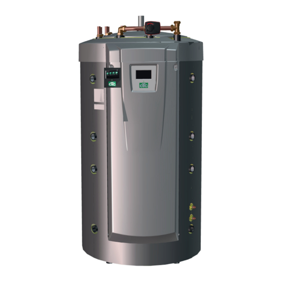
- Page 1 162 505 72-1 2020-09-22 Providing sustainable energy solutions worldwide Installation and Maintenance Manual CTC EcoZenith i555 Pro 3x400 V/ 1x230 V/ 3x230V Important! • Read carefully before use, keep for future reference. • Translation of the original instructions.
- Page 3 162 505 72-1 2020-09-22 Installation and Maintenance Manual CTC EcoZenith i555 Pro...
-
Page 4: Table Of Contents
Table of Contents Checklist 10. Troubleshooting/Appropriate measures _______________________________________________________________________ _________ Important to remember! 10.1 Information messages ______________________________________________ ____________________________________ Scope of delivery 10.2 Alarm messages _________________________________________________________ ____________________________________________ Safety instructions 11. Transportation, unpacking and installation _______________________________________________________ ____ Design of CTC EcoZenith i555 Pro 11.1 Transportation ____________________ ________________________________________________... - Page 5 Congratulations on buying your new product! You have just purchased a CTC EcoZenith i555 Pro, with Your CTC EcoZenith i555 Pro has built-in finned copper which we hope you will be very pleased. Read about how coils which provide plenty of hot water and another finned you can take care of your product on the following pages.
-
Page 6: Checklist
Checklist The checklist must always be completed by the installation engineer • If a service is performed, you may be required to provide this document. • Installation must always be done according to the installation and maintenance instructions. • Installation must always be carried out in a professional manner. •... -
Page 7: Important To Remember
Important to remember! Check the following points at the time of delivery and installation: • CTC EcoZenith i555 Pro must be transported and • Check for missing parts. stored in an upright position. When moving the • The product must not be installed where the product, it can be placed temporarily on its back. -
Page 8: Safety Instructions
Safety instructions Turn off the power with an omnipolar switch before doing any work on the product. The product must be connected to protective earth. The product is classified as IPX1. The product must not be rinsed with water. When handling the product with a hoist ring or similar device, make sure that the lifting equipment, eyebolts and other parts are not damaged. -
Page 9: Design Of Ctc Ecozenith I555 Pro
Design of CTC EcoZenith i555 Pro This chapter illustrates the main components and describes the subsystems which, in different confi gurations, form part of the main system. For more information about the EcoZenith confi gurations, refer to the “Pipe connections” chapter. Fresh Water Connections Main components Here you connect the property’s fresh... -
Page 10: Function Of Ctc Ecozenith I555 Pro
2. Function of CTC EcoZenith i555 Pro CTC EcoZenith i555 Pro is a multi-tank with almost unlimited possibilities The EcoZenith is intended for houses and properties with water-borne heat. Remember that The multi-tank features include intelligent control, a water volume of 540 menus which have litres, bivalent mixing valve, two DHW coils, a solar coil and two 9 kW electric not been defined... -
Page 11: Heating Circuit
Heating Circuit The EcoZenith is equipped with a bivalent mixing valve, which always delivers an even temperature, without variation, to the heating circuit. The bivalent mixing valve is controlled by an outdoor sensor and, optionally, by a room sensor. When operating with outdoor sensor alone, the desired curve inclination and adjustment are set. -
Page 12: Dhw
The final heating of the hot water takes place in the upper tank. It also acts as additional heating for the heating circuit when the lower tank is not enough. The DHW is heated using two finned copper tube coils of approx. 40 metres connected in parallel. -
Page 13: Heat Pump
Heat pump The EcoZenith is designed with two parts in order to ensure the heat pump operates to maximum possible economy. The heat pump is connected via two 3-way valves to the EcoZenith and ensures that the heat is directed into the upper and lower tanks, respectively. For instance, when the heat pump pumps towards the upper tank, the 3-way valves send the fl ow to the two uppermost connections, so that the fl ow enters port 1 and exits through port 2. - Page 14 2.3.2 Lower tank In the lower tank the heat pump operates to provide heat to the heating circuit. Heat pump operation is of so-called floating condensation type. However, the lower tank never drops below the lowest set temperature. Floating condensation operation is where the heat pump heats to the temperature required by the heating circuit.
- Page 15 2.3.5 Different Heat Pumps EcoZenith can control different types of heat pumps, CTC EcoAir (air source heat pump) and CTC EcoPart (ground source heat pump). The desired outdoor temperature at which the CTC EcoAir is prioritised over the CTC EcoPart is set in the “Installer/Settings/Heat pumps 1, 2, 3” menu under “Prio EcoAir/EcoPart”.
-
Page 16: Wood Boiler
2.3.6 Speed-controlled charge pump (accessory from CTC) Each heat pump should be provided with a separate charge pump that is controlled in tandem with its respective heat pump. If a speed-controlled PVM charge pump (accessory from CTC) is connected to the heat pump and controlled from the EcoZenith, the flow will be automatically set without any adjustment needed via the control valve. -
Page 17: Additional Boiler (Pellets, Oil, Gas, Electricity)
Additional boiler (pellets, oil, gas, electricity) The EcoZenith can control an external additional boiler (pellets, oil, gas, electricity). The additional boiler is connected to the upper tank. Use the menu to select whether the external additional boiler should have high or low priority. -
Page 18: Solar Energy
Solar Energy The EcoZenith contains a 10 m long 18 mm fi nned and internally grooved solar coil which manages approx. 10 m² of solar panel. On larger solar panel installations, the solar energy is connected via an external heat exchanger (see fi gure 2). -
Page 19: Recharging Bedrock/Ground
Recharging Bedrock/Ground If a liquid/water heat pump is connected, a 3-way valve can be installed on the solar circuit and connected to the brine circuit (the coil in the bedrock or the ground heat coil). The solar panel temperature should be factory set at 60°C warmer than the brine temperature for charging to start. -
Page 20: External Dhw Tank
External DHW tank An external DHW heater can be connected to the EcoZenith. This results in a greater stored DHW volume, which contributes to higher DHW capacity. The incoming cold water fi rst passes through the EcoZenith where it is heated before it fl ows into the DHW tank and out to the property’s taps. -
Page 21: External Buffer
2.10 External buffer The EcoZenith can be connected to one or more buffer tanks. This is mainly used when connecting wood and solar energy systems where the volume in the EcoZenith is not suffi cient. Via the accessory “Charging External Buffer Tank”, warm water can be sent both from the lower tank to the buffer tank(s) and from the buffer tank(s) back to the EcoZenith. - Page 22 2.10.2 Wood operation control The wood boiler charges the EcoZenith until the sensor of the lower tank reaches the factory-set 80 °C before the charge pump starts up and transfers hot water from the lower tank into the top of the fi rst buffer tank. Charging continues until the sensor in the lower tank has fallen 3 degrees (transfer starts at 80 degrees and stops at 77 degrees).
-
Page 23: Cooling Ctc Ecocomfort
2.11 Cooling CTC EcoComfort CTC EcoComfort is an accessory which utilises the cool temperatures of the borehole to create a cool indoor climate in summer. The extent to which you can cool a property depends on several factors, such as the rock temperature available for the case in point, the size of the house, the capacity of the fan convectors, the living area layout, etc. -
Page 24: The House Heating Curve
3. The house heating curve Your home's heating installation The House Heating Curve The heating curve is the central part of the product’s control system. It is the heating curve which determines the compensated flow temperature requirements for your property dependent upon the outdoor temperatures. It is important that the heating curve is correctly adjusted, so that you achieve the best operation and economy possible. - Page 25 Appropriate Default Values During installation you can seldom achieve a precise setting for the heating curve instantly. In this case, the values given below may provide a good starting point. Radiators with small heat-emission surfaces require a higher primary flow temperature. You can adjust the gradient (heating curve gradient) for your heating system under the "Installer / Settings / Radiator system"...
- Page 26 Examples of Heating Curves You can see in the diagram below how the heating curve changes with different Inclination settings. The gradient of the curve shows the temperatures that the radiators require at different outdoor temperatures. Primary Flow Temperature Curve Inclination The inclination value which is set is the primary flow temperature when the outside temperature is –15 °C.
- Page 27 Summer-time operation Primary Flow Temperature Heating All properties have internal heat gains (lamps, oven, ºC switched body heat, etc.), which means that the heating can be Heating up Heating up switched off when the outdoor temperature is lower than the desired room temperature. The better insulated the house is, the earlier the heating from the heat pump can be switched off.
-
Page 28: Dhw
4. DHW CTC EcoZenith i555 Pro has approx. 40 m of finned copper coils for the heating of DHW. These coils preheat the water in the lower tank and the water then runs through the upper tank for the final temperature increase. These two coils running parallel through the EcoZenith allow high flows with low pressure differential, creating excellent conditions for good DHW capacity and comfort. - Page 29 For higher DHW demands, it can be more economical to set a higher temperature in the lower tank instead of exceeding the temperature limit for the heat pump in the upper tank. However, this is less beneficial to heat pump operation for the radiator requirement because of the higher operating temperature.
-
Page 30: Technical Data
5. Technical data CTC EcoZenith i555 Pro 3x400V 1x230V CTC No. 589600001 589600002 Main dimensions on delivery 750x950x1700 Main dimensions when installed 886 x 1067 x 1700 Weight IP class IPX1 Insulation (polyurethane, PUR) Kvs value mixing valve 17-28kW (option mix. valve 27-45kW) m3/h 6.3 (10) Temperature thermostat overheating protector device... - Page 31 CTC EcoZenith i555 Pro 3x230V CTC No. 589600003 Main dimensions on delivery 750x950x1700 Main dimensions when installed 886 x 1067 x 1700 Weight IP class IPX1 Insulation (polyurethane, PUR) Kvs value mixing valve 17-28kW (option mix. valve 27-45kW) m3/h 6.3 (10) Temperature thermostat overheating protector device °C 92–98...
-
Page 32: Measurements
6. Measurements Heating connection, G 1 1/4" int. Expansion vessel/Top con/Lifting socket, G 1 1/4" internal Solar coil, Ø18 mm Cold water Ø22 mm Hot water Ø22 mm DHW circulation, Ø22 mm Radiator primary flow clamp ring 28 mm Radiator return clamp ring 28 mm Connection electric (behind the front) -
Page 33: Detailed Menu Descriptions
7. Detailed menu descriptions All settings can be confi gured directly on screen using the straightforward control unit. The large icons function as buttons on the touch display. Operational and temperature information is also displayed here. You can easily access the different menus to fi nd information on the operation or to set individual values. -
Page 34: Installation Wizard
Installation wizard When starting up the system and during reinstallation (refer to the "Installer/Service" chapter), several system options must be selected. The dialogue boxes which will then be displayed are described below. The values shown in the menu screenshots below are only examples. -
Page 35: Heating/Cooling
Heating/Cooling This is used to set the desired room temperature. Use the plus (+) and minus (-) buttons to set the desired temperature (setpoint), which is shown in brackets. The actual value is shown in front of the brackets. If heating circuit 3 or "Passive cooling" is installed, the symbol for room temperature is displayed with the The menu shows Heating circuit 1 with a room sensor and Heating circuit 2 without a room sensor. - Page 36 7.3.1 Outdoor sensor/room sensor errors If a fault occurs with an outdoor sensor, an outdoor temperature of -5°C is simulated so that the house does not get cold. The product’s alarm is triggered. If a fault occurs with a room sensor, the product automatically switches to operating according to the set curve.
- Page 37 7.3.3 Holiday You use this option to set the number of days that you want the set temperature to be consecutively reduced. For example, if you want to go on holiday. The value by which the temperature is lowered during the period is set in one of the following menus: When "Holiday Reduction"...
-
Page 38: Dhw
This menu is used to set the hot water comfort level and "Extra DHW". Extra DHW The "Extra DHW" function can be activated here. When the function is activated (by setting the number of hours The "Extra DHW" function is set to be active for 3.5 hours. using the plus sign in the "Hot Water"... -
Page 39: Ventilation
Ventilation Refer to the "Installation and Maintenance Manual" for the CTC EcoVent ventilation product. Weekly program In a weekly program (designated "Program" in the display menus), the periods can be set for when a function should be active or inactive during the weekdays. - Page 40 7.6.2 Setting a weekly program A weekly program can be set for most remotely controlled functions in the menus under "Installer/Settings". Click on the "Night Reduction" icon in the heating circuit However, schedules for "Night reduction", "Extra DHW" "Heating/Cooling" menu to set the weekly program. and "Ventilation"...
-
Page 41: Operation Data
Operation data Main menu page for "Operation Data" with liquid-to-water heat Main menu page for "Operation Data" with air-to-water heat pump CTC EcoPart connected. pump CTC EcoAir connected. When the pumps are in operation, the pump icons also rotate When the pumps are in operation, the pump icons also rotate on screen. - Page 42 7.7.1 Operation data, Control unit Status Shows the various operational statuses, refer to the table below: Delay mixing valve Shows the mixing valve delay (in minutes) for production Menu: "Operation Data/Control Unit". of heat from the upper tank to the heating circuit. Tank upper °C (60) (40) Temperature and setpoint (in brackets) in the upper...
- Page 43 7.7.2 Operation data, Heating circuit 1* Status Heating Shows the operational status of the heating circuit (see table below). Menu: "Operation data, heating circuit". The menu shows the Primary flow °C (48) current temperatures and status of defined heating circuits. Temperature and setpoint (in brackets) supplied to heating circuit.
- Page 44 7.7.3 Heat pump status* This menu appears when several heat pumps* have been defi ned. Liquid-to-water heat pumps: EcoPart = CTC EcoPart 400 Status On, DHW EcoPartM = CTC EcoPart 600M Heat pumps 1-3 (EcoAir, EcoAirM, EcoPart, EcoPartM or CombiAir) may have statuses according to the table Air/water heat pumps: below: EcoAir = CTC EcoAir 400...
- Page 45 7.7.4 Operation data, Compressor Status On, heating Shows the status of the heat pump. Refer to descriptions of status modes in the "Status, heat pump" menu. Model EcoPart The menu shows detailed operation data of the selected heat Shows the heat pump model. pump.
- Page 46 7.7.5 Stored Operation data This menu shows cumulative operation values. The operation values shown in the menu screenshots are only examples. The historical operational info presented varies depending on the language choice. Total operation time h 3500 Menu: "Operation data/Stored Operation data" Shows the total time the product has been powered.
- Page 47 7.7.6 Operation data, DHW Mode Comfort Shows the active DHW program (Economy/Normal/ Comfort). Tank upper °C (55) (65) Shows the current temperature in the DHW tank and "Operation Data/DHW" menu. the setpoint (in brackets) for heat pump operation and during additional heat. When the Legionella protection function is active, "L"...
- Page 48 7.7.7 Operation data, External buffer Status Loading buffer Shows the various operational statuses of the system. See table below. Ext. Upper buffer tank °C Indicates the current temperature in the upper part of "Operation Data/External Buffer Tank" menu. the buffer tank. Ext.
- Page 49 7.7.8 Operation Data, Wood Boiler System status Heating Shows the various operational statuses of the system. See the top table below. Status The bottom table below shows possible statuses of the "Operation Data/Wood Boiler" menu. wood boiler. Tank upper °C Shows the current temperature in EcoZenith’s upper tank.
- Page 50 7.7.9 Operation data, External Boiler Status The external boiler may have the following status. See the table below. Temperature °C Shows the temperature of the boiler. Menu "Operation Data/External boiler". Tank upper °C Shows the current temperature in EcoZenith’s upper tank.
- Page 51 7.7.10 Operation data, solar panels Status Charging DHW Shows status of solar panels. See table below. Outlet, Solar panels °C Shows the outgoing temperature from the solar panels. "Operation Data/Solar Panels" menu. Inlet, Solar panels °C Shows the incoming temperature to the solar panels. Pump Panel % This shows the actual percent of maximum capacity for the circulation pump.
- Page 52 7.7.11 Operation data, Pool Status Shows the current operating status ("On", "Blocked" or "Blocked Externally"). • "Blocked" means that pool heating has been blocked from the "Installer/Settings/Pool" menu. "Operation Data/Pool" menu. • "Blocked Externally" means that the pool is externally blocked via remote control or a weekly program.
- Page 53 7.7.12 Operation data, Ventilation For more information, see the Installation and Maintenance Manual for CTC EcoVent. Mode Reduced Shows the current ventilation mode. Setting options: Reduced/Forced/Normal/Custom. "Operation Data/Ventilation" menu. Fan speed in %. Highest level rH Highest measured value for humidity. Displayed if rH sensor from the CTC SmartControl series is installed.
-
Page 54: Installer
Installer This menu contains four sub-menus: • Display • Settings • Defi ne • Service Menu: "Installer". For "System Information", click the "i" button in the lower right corner of the screen in the "Installer" menu. This displays the product serial number, MAC address, and application and bootloader versions. - Page 55 7.8.2 Language Click a fl ag to select the language. The language selected is highlighted with a green square. To view more language options than those shown in the menu, scroll down the page, or press the down arrow key. Menu: "Installer/Display/Language".
-
Page 56: Settings
Settings This is used to set the parameters for your home’s heating requirements. It is important that this basic setting is right for your home. Values which are set incorrectly may mean that your property is not warm enough or that an unnecessarily large amount of energy is being used to heat your property. - Page 57 Heat mode, schedule This menu bar is displayed if a weekly program has been defined for the "HC Heat Mode, ext." function in the remote control menu. For more information, refer to: • chapter "Weekly Program" for schedule setting. • section "Def. Remote Control" of the "Installer / Define”...
- Page 58 Room temp. reduced, Night red °C -2 (0...-30) Room temp. reduced, Holiday °C -2 (0...-30) The menus are displayed if room sensors are installed If room sensors are installed, for the heating circuit. The number of degrees by which the "Room temp lowered..." menu is displayed.
- Page 59 Drying period mode Off (Off/1/2/3) Applies to Heating circuit 1. Drying period for newly built properties. The function limits the calculation of primary flow temperature (setpoint) for "Your home’s heating settings" to the schedule below. Mode 1 - Drying period for 8 days 1.
- Page 60 7.9.2 Settings Heat pumps In the "Heat pump" menu you make settings for the heat pumps which have been defined. Delay between comp. 30 (5...180) The delay time between when two heat pumps can start is set here. This value applies, for example, to the amount of time that will pass before the third heat pump is allowed to start, when the first and second heat pumps are operating, and so on.
- Page 61 7.9.3 Settings Heat pump 1-* Compressor Blocked (Permitted/Blocked) The heat pump is supplied with a blocked compressor. "Permitted" means that the compressor is allowed to start. Stop at outdoor temp °C -22 (-22...10) This menu relates to settings for the outdoor temperature at which the compressor is no longer permitted to operate.
- Page 62 Ext. Noise reduction rps 50 (20...120) Set the compressor speed value applicable for remote control. Read more in the "Installer/Define/Remote Control" chapter. Noise reduction schedule From this menu it is possible to start a weekly program with limited compressor speed to reduce the noise level. The "Weekly Program"...
- Page 63 7.9.4 Settings Electric heaters In the “Electric heaters" menu you can make settings affecting the operation of the electric heaters. Upper el. heater(s) kW 9.0 (0.3...9.0) Here you select the power that the upper electric heaters are allowed to emit. The setting range varies, see "Electrical data"...
- Page 64 Conv. factor curr. sensors 0 (1...10) This menu contains the factor the current sensor is to use. This setting is only performed if the connection has been installed for a current sensor for higher currents. Example: User (set) value 2 => 16 A will be 32 A. Tariff EL No (Yes/No) This menu bar is displayed if an "Input"...
- Page 65 7.9.5 Settings Upper tank Program DHW Available options are "Economy", "Normal" and "Comfort". Press "OK" to open the settings for the selected DHW program. The factory settings shown below apply to "Normal" mode. Refer to the "Parameter List" chapter for the "Economy" and "Comfort" modes’ factory settings.
- Page 66 Periodic extra DHW, days 14 (0...30) The menu defines the interval for the periodic increase of the external DHW tank to 65 °C to protect against legionella. 1 = Every day 2 = Every other day etc. Max temp diff end DHW °C 3 (2...7) If there is a heating requirement, DHW charging is interrupted earlier than the time at which the maximum...
- Page 67 For more information, refer to: • chapter "Weekly Program" for schedule setting. • section "Def. Remote Control" of the "Installer / Define” chapter for defining the remote control function. SmartGrid Low price °C 10 (Off, 1...30) The setpoint increase for heating the upper tank when "SmartGrid Low Price"...
- Page 68 Setpoint schedule °C 50 (20...60) This menu is used to set the setpoint to which the lower tank works during external activation (remote control) and when programming a heating schedule. This menu bar is displayed if a "Schedule" has been defined for the "Lower Tank"...
- Page 69 7.9.7 Settings Solar Panel dT max solar °C 7 (3...30) Here you can set the temperature difference determining when charging of solar energy is started. Type defined as “Coil”. When the solar panels are this many degrees warmer than the solar coil in the EcoZenith, the solar panels’...
- Page 70 Solar test tank min 4 (1...20) (Used only if evacuated tube solar collectors have been defined.) Once every 30 minutes (factory setting) to check whether tank charging is possible. The test is carried out at the set time interval. If sufficient temperature is obtained, tank charging continues;...
- Page 71 Settings Protection collector Max temp °C 120 (110...150) Protects the solar panels from high temperatures by allowing circulation in the solar panels even though the maximum temperature has been reached in the respective tank. For safety reasons, the temperature in the EcoZenith is never allowed to exceed 95°C.
- Page 72 7.9.8 Settings Wood boiler Start at flue gas temp °C 100 (Off/50...250) Wood status is activated when the flue gas temperature (B8) exceeds the set value in this menu and the temperature in the EcoZenith’s lower tank (B6) is equal to or above its setpoint.
- Page 73 7.9.9 Settings External Boiler Ext. boiler diff °C 5 (3...20) The value by which the temperature is allowed to drop below the stop temperature before the external boiler starts again is set here. Minimum boiler temp. °C 30 (10...80) The temperature at which the circulation pump will begin charging is set here.
- Page 74 7.9.10 Settings External buffer tank The buffer tank is charged from the lower tank of the EcoZenith but can be recharged in both the upper and the lower tanks. This menu bar is displayed if "Buffer Tank" has been defined in the "Installer/Define/External Buffer Tank" menu.
- Page 75 dT setpoint low °C 7 (2...50) Setting for the number of degrees by which the lower tank of the EcoZenith must exceed its reference value to start transfer to the external buffer tank. This setting applies to charging of solar energy when a heating need is present on the heating circuit.
- Page 76 7.9.11 Settings Pool Pool On (On/Blocked) Whether the pool heating should be "On" or "Blocked" is selected here. Pool temp °C 22 (20...58) The desired pool temperature is set on this menu bar. Pool diff °C 1.0 (0.2...5.0) The permitted difference between the stop and start temperature in the pool is specified here.
- Page 77 7.9.12 Settings Passive cooling Room temp. passive cooling °C 25.0 (10.0...30.0) This is used to set the desired room temperature for cooling. SmartGrid Low price °C 1 (Off, 1...5) Read more in the "Installer/Define/Remote control/ SmartGrid" menu. SmartGrid Overcapacity °C 2 (Off, 1...5) Read more in the "Installer/Define/Remote control/ Menu: "Installer/Settings/Passive Cooling".
- Page 78 7.9.13 Settings Communication Settings can be made here to control the product with a controlling system. 7.9.13.1 Ethernet DHCP Yes (Yes/No) "Yes" enables automatic connection to the network. If "No", custom router settings (IP address, Netmask and Gateway) as well as DNR setting must be made. Menu: "Installer/Settings/Communication".
- Page 79 7.9.14 Settings Ventilation/EcoVent Settings for the CTC EcoVent ventilation product are made here. For more information, see the "Installation and Maintenance Manual" for CTC EcoVent. 7.9.15 Settings Current sensor These menu bars are displayed if "Current Sensor" is defined in the "Installer/Define Current Sensor" menu. In the menu, specify the phases (L1, L2 and L3) to which the current sensors have been connected.
- Page 80 7.9.18 Save settings Custom settings can be saved to "Bank" 1-3 and on a USB drive here. The "USB" row is greyed out until the USB drive is installed. The rows show the date and time of saved settings. Press "OK" to confirm. 7.9.19 Load settings The saved settings can be recovered.
-
Page 81: Define
7.10 Defi ne The "Defi ne" menus specify which components and subsystems the system consists of. Menu: "Installer / Defi ne /Remote Control". 7.10.1 Def. Remote control This chapter describes all remote control functions; how they are set up and how they are used. The "Installer/Defi ne/Remote Control"... - Page 82 7.10.1.1 Setting the remote control function 1. Define an "Input" First, an input must be assigned to the function or functions to be controlled remotely. This is done in the "Installer/Define/Remote Control" menu. In the example, terminal block K24 is selected as the input for the "HC1 Heat Mode, Ext."...
- Page 83 7.10.1.2 Remote control functions The "Installer/Define/Remote Control" menu defines Inputs for current remote control functions: • terminal blocks K22, K23, K24, K25. • wireless accessories in the SmartControl series (Channel 1A, 1B, 2A, 2B, 3A, 3B and so on up to 7B). •...
- Page 84 Extra DHW schedule (Off/ K22-K25 /Channel 1A-7B / BMS DI0-7) Upon activation, production of extra DHW begins. When activation stops, extra DHW is produced for a run-on time of 30 min. The "Stop temperature" for extra DHW is set in the "Installer/Settings /DHW Tank/DHW program" menu.
- Page 85 Blocking Pool (Off/ K22-K25 /Channel 1A-7B / BMS DI0-7) This function is used to block pool heating. In the "Installer / Define/Remote Control" menu: • specify an "Input" for the remote control function. In the "Installer / Define / Pool" menu: •...
- Page 86 DHW circulation (Off/ K22-K25 /Channel 1A-7B / BMS DI0-7) The function allows DHW to circulate in the pipes between the taps and the DHW tank, ensuring that the DHW is hot when the taps are opened. In the "Installer / Define/Remote Control" menu: •...
- Page 87 HP charging (Off/ K22-K25 /Channel 1A-7B / BMS DI0-7) HP charging refers to heat pump charging of the external buffer tank. In the "Installer / Define/Remote Control" menu: • specify an "Input" for the remote control function. In the "Installer / Define/External Buffer Tank" menu: •...
- Page 88 SmartGrid A / SmartGrid B (Off/ K22-K25 /Channel 1A-7B / BMS DI0-7) In the "Installer / Define/Remote Control" menu: • specify an "Input" for the remote control function. There are three SmartGrid functions: • SmartGrid Low Price • SmartGrid Overcapacity •...
- Page 89 SmartGrid functions are enabled by activating the K22 (SG A) K23 (SG B) Function SmartGrid inputs in different ways according to the table Open Open Normal on the right. Open Closed Low price To enable the SmartGrid function "SG Low Price" Closed Closed Overcapacity...
- Page 90 HP Noise Reduction (1-)* (Off/ K22-K25 /Channel 1A-7B / BMS DI0-7) This function can be used to reduce compressor speed in order to reduce the noise level. In the "Installer / Define/Remote Control" menu: • specify an "Input" for the remote control function. In the "Installer / Define/Heat Pump"...
- Page 91 7.10.2 Def. Heating Circuit Heating circuit 1-* Heating Circuit 1 (HC1) is predefined by CTC EcoZenith. The rows under Heating Circuit 1 show the other definable heating circuits (HC2-3 in the example). The heating circuits shown depend, among other things, on which heating circuits are part of the defined System Type (1-6).
- Page 92 7.10.3 Def. Heat pump Heat pump 1-* Select a heat pump to be connected to the system and press "OK" to access the settings. Flow/level switch None/NC/NO This menu bar is displayed if an "Input" for remote control is defined for the "Flow/level switch" function in the "Installer/Define/Define Remote Control"...
- Page 93 7.10.5 Def. DHW tank DHW circulation (G40) Yes (Yes/No) Specify whether the circulation pump (G40) is connected to the DHW system. DHW extra Buffer (B43, G41)* No (Yes/No) Specify whether the circulation pump (G41) and external DHW tank sensor (B43) are connected to the DHW system.
- Page 94 7.10.5.1 Def. External buffer External buffer Yes (No/Yes) Specify whether an external buffer tank is connected to the system. HP charging ext. config. NC (None/NC/NO) Menu: "Installer / Define/External Buffer Tank". This menu defines the Normally Open (NO) or Normally Closed (NC) mode for the external control signal when remotely controlling HP charging of the buffer tank.
- Page 95 7.10.5.6 Def. Passive cooling Passive cooling Yes (Yes/No) Select "Yes" to connect passive cooling if the circulation pump (G3), mixing valve Y3, primary flow sensor (B3) and room sensor (B13) are connected to the system. Condense secured Yes (Yes /No) If the system is condensation-proofed, significantly lower temperatures are permitted at various points in the system.
- Page 96 7.10.5.7 Def. Pool Pool No (Yes/No) Select "Yes" to connect the pool if circulation pumps (G50) and (G51) and pool sensor (B50) are connected to the system. Block pool ext. config. NO (None/NC/NO) This menu bar is displayed if an "Input" for remote control is defined for the "Block Pool"...
- Page 97 7.10.7 Def. Solar panels* Solar panels No (Yes/No) Select "Yes" to connect solar panels if the circulation pump (G30) as well as the "In" solar panel sensor (B30) and "Out" solar panel sensor (B31) are connected to the system. Type Only DHW Specify whether the solar energy heat should be supplied:...
- Page 98 7.10.8 Def. SMS Activate No (Yes/No) If "Yes" is selected, the menus below are displayed: Level of signal The signal strength of the reception is shown here. Phone Number 1 The first activated phone number is shown here. Phone Number 2 Menu: "Installer / Define / SMS".
-
Page 99: Service
7.11 Service NB: This menu is intended for the installer only. Menu: "Installer/Service". 7.11.1 Function test From this menu, the installer can test the connection and function of separate components of the heating circuit. When this menu is activated, all control functions are stopped. - Page 100 7.11.1.3 Test Heat Pump* Select the heat pump (1-*) for function testing and select "Go to Menu Test". HP Compressor Off (On/Off) When the compressor is being function tested, the brine and charge pump are also operating so that the compressor does not trigger its pressure switches.
- Page 101 7.11.1.5 Test DHW circ/ Solar/ Pool The following pumps/valves are function tested from this menu: DHW circulation pump (G40) On (On/Off) Switches the circulation pump "On" and "Off". DHW tank pump (G41) On (On/Off) Switches the circulation pump "On" and "Off". Solar panel pump (G30) 0 (0...100 %) Menu: "Installer/Service/ Function Test/DHW Circulation/Solar/...
- Page 102 7.11.2 Alarm log In the alarm log, up to 500 alarms can be displayed at the same time. An alarm which reoccurs within an hour is ignored so as not to fill up the log. Click an alarm row to see more information about an alarm.
- Page 103 7.11.4 Settings coded This menu is intended to set the manufacturer’s operational and alarm limits. A 4-digit code must be specified to be able to amend these limits. However, you can also take a look without any code to see what options feature in the menu.
- Page 104 7.11.9 Calibration Sensor Primary flow HC1 °C (B1) 0.0 (-3.0...3.0) Correction of primary flow sensor (B1). Primary flow HC2 °C (B2) 0.0 (-3.0...3.0) Correction of primary flow sensor (B2). Primary flow HC3 °C (B3) 0.0 (-3.0...3.0) Correction of primary flow sensor (B3). Room temperature 1 °C (B11) 0.0 (-3.0...3.0) Correction of room sensor (B11).
-
Page 105: Parameter List
8. Parameter list Factory Factory setting setting Heating circuit Tariff HP schedule Max primary flow °C Passive cooling brine pump on Min primary flow °C Silent mode, schedule Heating, mode Auto Electric heaters Heating mode, ext. Upper el. heater(s) kW Heat mode, schedule Lower el. - Page 106 Factory Factory setting setting Setpoint schedule °C HP charging Lower tank HP charging schedule Lower tank Pool SmartGrid Low Price °C Pool Blocked Pool temp °C SmartGrid Overcapacity °C Pool diff °C Solar Panel Pool priority °C dT max solar °C SmartGrid Low Price °C dT min solar °C SmartGrid Overcapacity °C...
-
Page 107: Operation And Maintenance
9. Operation and Maintenance Once your new EcoZenith has been installed, you and your installer should together check that the system is in perfect operating condition. Let the installer show you where the switches, controls, fuses etc. are, so that you know how the system works and how it should be maintained. - Page 108 Room Sensor A room sensor, which should always be fitted (up to three room sensors can be connected), ensures that the temperature in the room is always suitable and stable. For the sensor to provide the correct signals to the control unit, radiator thermostats should always be fully open in the area where the room sensor is located.
-
Page 109: Troubleshooting/Appropriate Measures
10. Troubleshooting/Appropriate measures CTC EcoZenith i555 Pro is designed to provide reliable operation and high levels of comfort, as well as have a long service life. Various tips are given below which may be helpful and guide you in the event of an operational malfunction. - Page 110 Current Monitor (protection for main fuses) CTC EcoZenith i555 Pro has a built-in current monitor. If the system is fitted with a current sensor (included), the property’s main fuses are continuously monitored to ensure they are not overloaded. If this should happen, electric stages are disconnected from the EcoZenith.
-
Page 111: Information Messages
10.1 Information messages Information messages are displayed when appropriate and are intended to inform users about various operational situations. [I013] Start delay [I021] Ext. Ctrl Heating HC1 The compressor is not allowed to start too quickly when [I022] Ext. Ctrl Heating HC2 it has stopped. -
Page 112: Alarm Messages
10.2 Alarm messages If a fault occurs with e.g. a sensor, an alarm is triggered. A message appears on the display with information about the fault. You reset the alarm by pressing the “Reset alarm” button on the display. If several alarms are triggered, they are displayed one after the other. - Page 113 Alarm messages Description [E057] Motor protect high curr. High current into the compressor has been detected. Press reset and check whether the alarm recurs. If the fault recurs, contact your installer. [E058] Motor protect low curr. Low current into the compressor has been detected. Press reset and check whether the alarm recurs.
- Page 114 Alarm messages Description [E052] Phase 1 missing This message appears in the event of a phase failure. Check the product’s fuses. If this does not help, the installation should be checked by an [E053] Phase 2 missing authorised person. [E054] Phase 3 missing [E010] Compressor type? This message appears if no information about the compressor type is available.
-
Page 115: Transportation, Unpacking And Installation
11. Transportation, unpacking and installation This section is intended for the technician responsible for one or more of the installations necessary for the CTC EcoZenith i555 Pro to perform according to the property owner's wishes. Take your time going through functions and settings with the property owner and answer any questions. - Page 116 When the rear insulation is in place, tension bands can be used to hold it firmly against the tank. Attach the insulation sections to each other using the 25 graphite-grey screws provided. The screw positions have been pre- The tension bands can drilled.
-
Page 117: Parts List
12. Parts list 01. CTC EcoZenith i555 Pro upper tank B2. Sensor, primary flow to heating circuit 2 02. CTC EcoZenith i555 Pro lower tank B3. Sensor, primary flow to heating circuit 3 Alternative: Sensor, primary flow CTC EcoComfort (Cooling) 03. -
Page 118: Schematic Diagram
13. Schematic diagram ���������������� ���������������� ���� ���� ��������� ��������� ��� ��� ���� ���� ��� ��� ����� ����� ������ ������ ��� ��� ���E�� ���E�� ���E��� ���E��� ���E�� ���E�� �7 �7 ���� ���� ���� ���� ���� ���� �E��� �E��� �E��� �E��� �E��� �E���... - Page 119 �5���5�� �5���5�� ���� ���� �5�� �5�� ���� ���� �5 �5 ��������� ��������� �4 �4 �5���5�� �5���5�� � � 2� 2� ���� ���� ��� ��� ����� ����� ��� ��� � � ��� ��� ���� ���� ���� ���� ��� ��� ��5� ��5� �����...
-
Page 120: Pipe Installation
14. Pipe installation The installation must be carried out in accordance with current heating and DHW standards. The product must be connected to an expansion vessel in an open or closed system. Do not forget to flush the heating circuit clean before connection. - Page 121 Fit the drain valve (separate package) to one of the EcoZenith’s lower connections. The adapter for this is provided in the package. The drain valve can also be fitted into a low lying pipe. Manometer – system pressure Fit a manometer to the expansion pipe or radiator return pipe. Expansion vessel connection The EcoZenith is best connected to a closed expansion vessel.
- Page 122 14.3.1 CTC EcoZenith i555 Pro – Radiator system The CTC EcoZenith i555 Pro can be connected to three different radiator systems with separate room sensors. Mixing valve (Y1) is the main mixing valve and feeds heating circuit 1. Mixing valves (Y2) and (Y3) for heating circuits 2 and 3 are sub-mixers. This means that mixing valve (Y1) controls the maximum temperature to mixers (Y2) and (Y3).
- Page 123 14.3.2 CTC EcoZenith i555 Pro – Heat pump Heat pump 1 is connected to 3-way valves for changing between the upper and lower tanks. Heat pumps 2 and 3 are connected directly to the lower Only heat pump 1 tank for supplying radiators. may be connected to the 3-way valves Ensure that the ports on the 3-way valves (Y21) are set as in the schematic...
- Page 124 14.3.3 CTC EcoZenith i555 Pro – Solar heating Solar panels (17) can be connected directly to the EcoZenith’s built-in solar coil (11). The solar coil is the finned type. The fluid is pumped from the coil by a speed controlled solar pump (G30). In a larger system with several solar panels of more than about 10 m², the panels are connected to an intermediate heat exchanger (05) and the changing solar energy is pumped to the EcoZenith’s lower tank by a speed controlled pump (G32).
- Page 125 14.3.4 CTC EcoZenith i555 Pro – DHW Figure 1 Shows how DHW circulation can be connected to the EcoZenith. The domestic hot water is circulated by pump (G40). New DHW from the finned coil is mixed in by the mixing valve (32), and cooled water is released down to the coil for reheating.
- Page 126 14.3.5 CTC EcoZenith i555 Pro – Wood boiler The upper and lower connections are used for connecting a wood boiler to the EcoZenith. Alternatively, the expansion connection and lower connection are used. This means that the flow from the wood boiler passes through the entire EcoZenith.
- Page 127 14.3.6 CTC EcoZenith i555 Pro – Buffer tanks One or more buffer tanks can be connected to increase the water volume; this is done most commonly in connection with wood or solar energy operation. When the EcoZenith controls the charging of the wood boiler and solar energy, buffer tanks can be charged with lower temperatures and thus higher efficiency.
- Page 128 14.3.7 CTC EcoZenith i555 Pro – Additional boiler When connecting an additional boiler (oil, pellets, electricity or gas),it must be connected to the EcoZenith’s upper tank connections. Circulation is undertaken by the pump (G44), which is controlled by the EcoZenith. The sensor (B17) senses the boiler temperature in the external boiler.
- Page 129 14.3.8 CTC EcoZenith i555 Pro - Pool A pool is connected to the EcoZenith’s lower tank. This means that the pool is heated by the same energy source as the heating circuit prioritises, for example, heat pump or solar panel. One pump (G50/G51, at the top of the drawing) circulates radiator water from the upper connection on the EcoZenith’s lower tank (02) to the pool heat exchanger (14), on to the heating circuit’s return pipe and back to the EcoZenith’s lower tank.
- Page 130 14.3.9 EcoZenith – CTC EcoComfort (Cooling) CTC EcoComfort is an accessory which utilises the cool temperatures of the borehole to create a cool indoor climate in summer. By connecting EcoComfort to the separate fan convectors, its water is cooled using the bedrock’s cooler collector water.
-
Page 131: Electrical Installation
15. Electrical installation This chapter describes how the various electrical components are connected in line with the designations reproduced in schematic diagrams and wiring diagrams. Installation and connection in the EcoZenith must be undertaken by an authorised electrician. All wiring must be installed according to applicable regulations. -
Page 132: Positioning Of Electrical Components
15.1 Positioning of electrical components Connection to display A 1 Expansion card A3 Power supply Connections X1-X7 L1 – 3x400 V/(1x230 V) L2 – 3x400 V L3 - 3x400V Fast-blow fuses F1/F2 Sensor, upper B5 3x400V – Socket for extra electric heater E5. -
Page 133: Omnipolar Safety Switch
15.2 Omnipolar safety switch The installation should be preceded by an omnipolar safety switch according to overvoltage category III, which ensures disconnection from all electric power sources. 15.3 Heat pump power supply NB: The heat pump is powered separately. Not by CTC EcoZenith i555 Pro. 15.4 Communication between the B=Brown... - Page 134 (G1) Circulation pump, heating circuit 1 230 V 1N ~ Connected on the circuit card/ block: Phase: pole A31 Neutral: pole A33 Earth: pole PE Check that the pump is correctly connected by test running it in the "Installer/ Service/Function Test" menu in the control system. (G2) Circulation pump, radiator system 2 230 V 1N ~ Connected on the circuit card/...
- Page 135 (G11, G12, G13) Charge pumps, HP1, HP2 and HP3 230 V 1N~ The charge pumps can be controlled by the EcoZenith. The charge pumps can be connected to the relay card/terminal block: (G11) Charge pump 1 WILO Stratos Para GRUNDFOS UPM GEO 25-85 Relay output 8 A PWM+: brown...
- Page 136 (G30, G32) Solar pumps The solar PWM pumps (G30 and G32) of model WILO Stratos PARA differ from the other PWM pumps. If the PWM control signal is interrupted, the solar pumps stop, whereas the other PWM pumps work at 100% power if the signal is interrupted.
-
Page 137: Selecting Mode Setting
1. Briefl y press the circulation pump arrow to show the operating mode to which the pump is set. After 2 seconds, the operational information screen will be displayed again. 2. Pressing the circulation pump arrow for 2 seconds will cause the LEDs to fl ash and the mode setting can then be changed. - Page 138 (G32) Circulation pump, plate heat exchanger, solar heating, Wilo Stratos Para 230 V 1N~ The heat exchanger pump is connected to the following terminal blocks: (G32) Pump, expansion card X5: Note the cable colours! PWM+: white X5 pole 3 GND: brown X5 pole 4 Check the function by test running the pump in the "Installer/Service/...
- Page 139 (G40) Circulation pump for DHW 230 V 1N~ The circulation pump is connected to the following terminal blocks: (G40) Circulation pump, expansion card X6: Phase: X6 pole 1 Zero: X6 pole 3 Earth: X6 pole 2 Check that the pump is correctly connected by test running it in the "Installer/Service/Function Test"...
- Page 140 (G43) Circulation pump, external buffer tank charging 230 V 1N~ The circulation pump is connected to the following terminal blocks: (G43) circulation pump, extension card X7: Phase: X7 pole 27 Zero: X7 pole 29 Earth: X7 pole 28 Check that the pump is correctly connected by test running it in the "Installer/Service/Function Test"...
- Page 141 (G50) and (G51) Circulation pumps, pool 230 V 1N~ Both pumps (G50) & (G51) are connected to the following terminal blocks: Pumps pool (G50) and (G51), expansion card X7: Phase: pole 33 Neutral: pole 35 Earth: pole 34 Pole 33 is connected to an external connection box which distributes voltage to the charge pump (G50) and circulation pump (G51).
- Page 142 (Y21) 3-way valves, DHW 230 V 1N~ 2.5 m cable 1.5 mm² When relay output A18 is powered, the fl ow is to the upper tank for DHW charging. When it is not powered, the fl ow is to the lower tank. The 3-way valves are connected to the following terminal blocks: (Y21) 3-way valves, DHW Relay output (black):...
- Page 143 (Y40) 3-way valve external buffer tank 230 V 1N~. 2.5 m cable 1.5 mm² Knob The 3-way valve is connected to the following terminal blocks: (Y40) 3-way valve, extension card X6: (Y40) 3-way valve, charging/discharging buffer Actuator Relay output (black): X6 pole 4 Phase (brown): X6 pole 5...
-
Page 144: Sensor (Safety Extra-Low Voltage (Selv))
15.6 Sensor (Safety Extra-Low Voltage (SELV)) The sensors that form part of each system solution must be fitted to the relay card/terminal block as follows: All sensors are temperature sensors. Room sensors (B11, B12, B13) (B13) Optional room sensor for CTC EcoComfort (Cooling). Room sensors should be installed at head height in open areas of the property with good air flow and where a representative temperature can be expected (not close to sources of heat or cold). - Page 145 Outdoor sensor (B15) The outdoor sensor should be fitted to the outer wall of the house, preferably in a north-northeastern or north-northwestern direction. The sensor should be placed out of direct sunlight. However, where this is difficult to achieve it can also be shielded from the sun by a screen.
- Page 146 Primary flow sensor (B1, B2, B3). (B3) Or primary flow sensor for CTC EcoComfort (passive cooling) The sensors sense the outgoing temperature to the radiators. Secure the primary flow sensor to the pipe using straps or similar. Most important is the position of the tip of the sensor as this is the part that detects the temperature.
- Page 147 (B17) Sensor external boiler Position: in a sensor pipe or jacket surface on the boiler. The sensor is connected to the relay card in positions G71 and G72. Sensor type: NTC 22k (B30) Sensor in to solar panels Position: on the return pipe into the solar panels. The sensor is connected to expansion card X1 in positions 3 and 4.
-
Page 148: Current Sensor Connection
15.7 Current sensor connection The three current sensors, one for each phase, are fitted on the fuse panel in the following manner: Each phase from the electricity distribution board supplying the product is channelled through a current sensor before termination at the relevant terminal. -
Page 149: Settings To Be Carried Out By The Installation Electrician
15.8 Settings to be carried out by the installation electrician The following settings shall be made by the installation electrician after installation: • Select main fuse size. • Select effect limitation. • Check room sensor connection. • Check that the sensors connected indicate reasonable values. •... -
Page 150: Installation Of Optional Electric Heater
16. Installation of optional electric heater CTC EcoZenith i555 Pro has two 9 kW electric heaters, both factory installed. A third 9 kW electric heater can also be installed thus giving total installed heating power of 27 kW. The third electric heater is a CTC accessory and is connected as follows: Disconnect the electrical supply to the EcoZenith. -
Page 151: Installation Of Additional Boiler
17. Installation of additional boiler CTC EcoZenith i555 Pro is able to control either a third electric heater or an external additional boiler. Under no circumstance may these be connected at the same time. To connect an additional boiler, EcoZenith’s electrical cabling must be rewired. -
Page 152: Wiring Diagram Relay Card 3X400V
18. Wiring diagram relay card 3x400V CTC EcoZenith i555 Pro... - Page 153 CTC EcoZenith i555 Pro...
-
Page 154: Wiring Diagram Relay Card 1X230V
19. Wiring diagram relay card 1x230V CTC EcoZenith i555 Pro... - Page 155 CTC EcoZenith i555 Pro...
-
Page 156: Wiring Diagram Relay Card 3X230V
20. Wiring diagram relay card 3x230V CTC EcoZenith i555 Pro... - Page 157 CTC EcoZenith i555 Pro...
-
Page 158: Wiring Diagram For Expansion Card
21. Wiring diagram for expansion card CTC EcoZenith i555 Pro... -
Page 159: Parts List Wiring Diagram
22. Parts list Wiring diagram Display Circulation pump flue gas controlled Relay/main card Charge pump 1 Expansion card Charge pump 2 Primary flow sensor 1 NTC 22 Charge pump 3 Primary flow sensor 2 NTC 22 Circulation pump, solar panel Primary flow sensor 3 NTC 22 Pump, bore hole recharging... -
Page 160: Resistances For Sensors
23. Resistances for sensors NTC 3.3K NTC 22K NTC 150 Brine, HP, Flue gas sen- Electric Boiler, Outdoor sen- Temperature Temperature Temperature Primary Flow, °C °C °C Resistance Ω Room Sensor Resistance Ω Resistance Ω 1027 1167 1330 1522 1746 2010 2320 2690... -
Page 161: Installation Communication
24. Installation Communication The back of the display unit has 3 communication ports. Menu: "Installer/Defi ne/Communication". Communication Display communication ports Port 1. RS485 port without galvanic protection. For external equipment, e.g. BMS, CTC AXS Defi ne AXS: "Yes" permits BMS via the RS485 port and "CTC AXS"... -
Page 162: Fitting The Ethernet Cable
24.1 Fitting the ethernet cable In order to define and enable connection to the network and app, an ethernet cable must be connected as described below. Route the ethernet cable on the left side of the product in the space between the side insulation and the top insulation. -
Page 163: Ctc Remote - Screen Mirroring
24.2 CTC Remote - Screen Mirroring • Connect the ethernet cable, see previous page. • Installer/Defi ne/Communication/Web – Yes. Permits the product to connect with unencrypted web traffi c on local area networks. Internet router and fi rewall required. Tablet/Smartphone/PC as a touchscreen for local area network •... -
Page 164: First Start
25. First start CTC EcoZenith i555 can be started without a room sensor being installed; the heating will instead be controlled by the heat curve set for the property. The room sensor can however always be fitted for the alarm LED function. In this case, deselect the room sensor in the "Installer/Define"... -
Page 165: First Start
25.2 First start Switch on the power using the safety switch. The display will come on and the operating lamp will start to light up. Factory-set values will apply, so for instance, the connected heat pumps’ compressors are blocked. The first time the EcoZenith is started up or if it is restarted within 24 hours after start- up, items 1–3 are displayed. - Page 166 25.2.1 Getting started Define system • The EcoZenith senses whether primary flow sensors 1 and 2 and room sensors 1 and 2 are connected and if so, automatically defines heating circuits 1 and 2 “Yes” with the associated room sensor “Yes”. •...
- Page 167 CTC EcoZenith i555 Pro...
- Page 168 162 505 72-1 2020-09-22 Enertech AB. P.O Box 309 SE-341 26 Ljungby Sweden. www.ctc.se, www.ctc-heating.com...
Need help?
Do you have a question about the EcoZenith i555 Pro Series and is the answer not in the manual?
Questions and answers