Table of Contents
Advertisement
Quick Links
WARNING:
If the information in these instructions is not followed exactly, a fire or explosion may result
causing property damage, personal injury or loss of life.
DO NOT PLACE ARTICLES ON OR AGAINST THIS APPLIANCE.
DO NOT USE OR STORE FLAMMABLE MATERIALS NEAR THIS APPLIANCE.
DO NOT SPRAY AEROSOLS IN THE VICINITY OF THIS APPLIANCE WHILE IT IS IN OPERATION.
DO NOT MODIFY THIS APPLIANCE.
-
Do not store or use gasoline or other flammable vapors and liquids in the vicinity of this or any other appliance.
WHAT TO DO IF YOU SMELL GAS
• Do not try to light any appliance.
• Do not touch any electrical switch; do not use any phone in your building.
• Immediately call gas supplier from a neighbor's phone. Follow the gas supplier's instructions.
• If you cannot reach your gas supplier, call the fire department.
-
Installation and service must be performed by a qualified installer, service agency or the gas supplier.
This appliance may be installed in
an aftermarket permanently
located, manufactured home (USA
only) or mobile home, where not
prohibited by local codes.
This appliance is only for use
with the type(s) of gas indicated
on the rating plate. A conversion
kit is supplied with the appliance.
Installation Manual
Installer:
After installation give this manual to the home-
owner and explain operation of this heater.
Copyright 2018, T.I.
$10.00
100-01474
Pro Builder
42 Linear GSB2
• Direct Vent Fireplace
• Natural Gas or Propane
• Vent Horizontally or Vertically
• Standard Residential
• Mobile Home Approved
Listed by
AS 4553-2008
GMK10166
IAPMO-R&T OCEANA
Dragon Wholesaling Pty. Ltd.
Unit 4, 16 Lexington Drive
1/30/18
Bella Vista NSW
Australia 2153
Advertisement
Table of Contents

Related Manuals for Travis Industries Pro Builder 42 Linear GSB2


Summary of Contents for Travis Industries Pro Builder 42 Linear GSB2
- Page 1 Pro Builder 42 Linear GSB2 • Direct Vent Fireplace • Natural Gas or Propane • Vent Horizontally or Vertically • Standard Residential • Mobile Home Approved Listed by AS 4553-2008 GMK10166 IAPMO-R&T OCEANA WARNING: If the information in these instructions is not followed exactly, a fire or explosion may result causing property damage, personal injury or loss of life.
-
Page 2: Overview
This appliance was listed by IAPMO to AS 4553-2008. The listing label is attached to the appliance near the gas control valve. A copy is shown to the right. © Travis Industries 1/30/18 - 1474 PB 42 GSB2 Install Aust... -
Page 3: Table Of Contents
Vent Configuration: Horizontal Termination with Vertical Rise ............31 Termination Requirements ........32 Hearth Requirements ..........33 Facing Requirements ..........34 Standard vs. Extended Position ........35 © Travis Industries 1/30/18 - 1474 PB 42 GSB2 Install Aust... - Page 4 Never remove, replace, modify or substitute any part of the heater unless instructions are given in this manual. All other work must be done by a trained technician. Don't modify or replace orifices. The viewing glass should be opened only for conducting service. © Travis Industries 1/30/18 - 1474 PB 42 GSB2 Install Aust...
- Page 5 It is imperative that control compartments, burners, and circulating air passageways of the appliance be kept clean. Travis Industries, Inc. grants no warranty, implied or stated, for the installation or maintenance of your heater, and assumes no responsibility of any consequential damage(s). SAFETY WARNINGS: ...
-
Page 6: Installation Options
4-7/8" 788mm 124mm 1-1/2" 38mm 3-3/4" 96mm 47-1/8" * 1197mm * 15-7/8" * 404mm * * Includes the required 1/2" clearance to each side and rear of the fireplace. © Travis Industries 1/30/18 - 1474 PB 42 GSB2 Install Aust... -
Page 7: Packing List
Install the drywall. Install the hearth (if applicable). Install the facing (if applicable). Install the mantel (if applicable). Finalize the installation (see page 39). © Travis Industries 1/30/18 - 1474 PB 42 GSB2 Install Aust... -
Page 8: Fireplace Placement Requirements
The top of the control door (firebox opening) is approximately 8-3/4” (223mm) above the base of the fireplace. For a typical raised fireplace of 36” (915mm), place the fireplace on a platform 27.25” (693mm) tall. © Travis Industries 1/30/18 - 1474 PB 42 GSB2 Install Aust... -
Page 9: Televisions Placed Above The Fireplace
The homeowner must understand that Travis Industries does not take responsibility for any negative impact to televisions placed near this fireplace. -
Page 10: Using A Buildout Above Fireplace And Television
The homeowner must understand that Travis Industries does not take responsibility for any negative impact to televisions placed near this fireplace. -
Page 11: Using A Buildout Below A Television
The homeowner must understand that Travis Industries does not take responsibility for any negative impact to televisions placed near this fireplace. -
Page 12: Minimum Framing Dimensions
(for qualified installers only) Minimum Framing Dimensions 45-1/4" 1150mm 34-1/2" 877mm 47-1/8" 1197mm 15-7/8" 404mm The fireplace enclosure must be a minimum 45-1/4” (1150mm) tall. Do not build into the fireplace enclosure. © Travis Industries 1/30/18 - 1474 PB 42 GSB2 Install Aust... -
Page 13: Standoff Assembly
These standoffs, when properly constructed, provide a guide for the required 1/2" (13mm) clearance. NOTE: The rear standoffs are bent around the rear corners of the fireplace as shown below to the right. Rear Standoffs © Travis Industries 1/30/18 - 1474 PB 42 GSB2 Install Aust... -
Page 14: Nailing Brackets
(platform). Standard Position Extended Position (nailing brackets as shown below) (rotate nailing brackets as shown below) © Travis Industries 1/30/18 - 1474 PB 42 GSB2 Install Aust... -
Page 15: Standard Vs. Extended Position
If the unit is being installed in the extended position, the standoff/heat shield assembly must be repositioned back ½” (13mm) (see illustration below). NOTE: see pages 14 & 35.for additional details about standard vs. extended installations. Extended Position Standard Position © Travis Industries 1/30/18 - 1474 PB 42 GSB2 Install Aust... -
Page 16: Header And Pipe Shield Installation
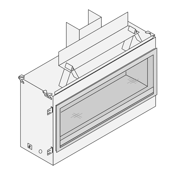
(Keep the screws for reinstallation). At each of the perforations, bend the sides of the pipe shield backwards 90° as shown below. NOTE: The bottom flanges should be facing outward Tabs face out. Bend at perforations © Travis Industries 1/30/18 - 1474 PB 42 GSB2 Install Aust... - Page 17 Remove the (4) screws, (2) from each side of the starter collar. Line up the holes on the pipe shield tabs with the holes from the screws you just removed. Use the screws to attach the pipe shield to the top of the fireplace. Remove screws © Travis Industries 1/30/18 - 1474 PB 42 GSB2 Install Aust...
- Page 18 Bend the legs at the perforations as shown below and attach the foot of the standoff to the top of the fireplace using the screw removed earlier in this step. Remove screw © Travis Industries 1/30/18 - 1474 PB 42 GSB2 Install Aust...
- Page 19 Bend tabs down 90° Align holes When finished the fireplace should be configured like the picture below. © Travis Industries 1/30/18 - 1474 PB 42 GSB2 Install Aust...
-
Page 20: Corner Installations
NOTE ON PIPE SHIELD: When venting in a corner application, one side of the pipe shield may be disconnected from the top of the fireplace and bent at a 45° angle. © Travis Industries 1/30/18 - 1474 PB 42 GSB2 Install Aust... -
Page 21: Removing The Front Panel
To remove the front cover 1/4" Nutdriver/Wrench (a) Remove the center wingnuts. (b) Loosen the two outer screws. (c) Rotate the front panel down. (d) Remove the front cover. © Travis Industries 1/30/18 - 1474 PB 42 GSB2 Install Aust... -
Page 22: Gas Line Requirements
The supply regulator (the regulator that attaches directly to the residence inlet or to the propane tank) should supply gas at the suggested input pressure listed above. Contact the local gas supplier if the regulator is at an improper pressure. © Travis Industries 1/30/18 - 1474 PB 42 GSB2 Install Aust... -
Page 23: Gas Line Location
Remove the knock-out in the desired location (you may wish to remove both knockouts if routing electrical through the base as well). Route the flex gas line (with shutoff valve) to the desired location. © Travis Industries 1/30/18 - 1474 PB 42 GSB2 Install Aust... -
Page 24: Electrical Connection
Attach the junction box to the baseplate (make sure all wiring is kept from contacting hot or moving components). Attach the cover plate to the left side. © Travis Industries 1/30/18 - 1474 PB 42 GSB2 Install Aust... -
Page 25: Optional Wall Switch Or Thermostat Installation
To wire the heater in parallel, follow the directions below: To wire the heater in series, follow the directions below: On / Off Switch On / Off Switch Thermostat (or External Switch) Wires Thermostat (or External Switch) Wires © Travis Industries 1/30/18 - 1474 PB 42 GSB2 Install Aust... -
Page 26: Vent Requirements
Horizontal sections require a 1/4" (6mm) rise every 12" (305mm) of travel. Horizontal sections require non-combustible support every three feet (e.g.: plumbing strap). © Travis Industries 1/30/18 - 1474 PB 42 GSB2 Install Aust... -
Page 27: Approved Vent Configurations
# 5. Tighten the screws to secure the restrictor. # 2... (open - stock position) # 1 # 6... # 11 Back of Firebox © Travis Industries 1/30/18 - 1474 PB 42 GSB2 Install Aust... -
Page 28: Diffuser
Bend the round portion of the diffuser so it is flat (open). DIFFUSER SIDE VIEW Secure the flattened Before (Closed - Stock) diffuser plate with the screws removed earlier. After (Open) © Travis Industries 1/30/18 - 1474 PB 42 GSB2 Install Aust... -
Page 29: Minimum Vent Configuration
The termination must fall within the shaded area shown in the chart. Use the indicated restrictor positions. One 45° elbow may be used on the horizontal run. HINT: Use minimum vent kit “H” (96200332) from Travis Industries (additional vent may be required). Exhaust Restrictor # 1 (stock) -
Page 30: Vent Configuration: Vertical Termination
(Horizontal Length = H1 + H2). It may be a 90° or 45° elbow. This is considered a vertical elbow © Travis Industries 1/30/18 - 1474 PB 42 GSB2 Install Aust... -
Page 31: Vent Configuration: Horizontal Termination With Vertical Rise
(Horizontal Length = H1 + H2). It may be a 90° or 45° elbow. This is considered a vertical elbow © Travis Industries 1/30/18 - 1474 PB 42 GSB2 Install Aust... -
Page 32: Termination Requirements
Minimum 12” (305mm) above the roof line (for vertical terminations) Minimum 24” (610mm) horizontal clearance to any surface (such as an exterior wall) – for vertical terminations NOTE: Measure clearances to the nearest edge of the exhaust hood. © Travis Industries 1/30/18 - 1474 PB 42 GSB2 Install Aust... -
Page 33: Hearth Requirements
A non-combustible hearth may be constructed in front of the fireplace (see illustration below). A non-combustible hearth may be installed in front of the fireplace. The entire structure must be non- combustible. Do not build the hearth above the screen assembly. © Travis Industries 1/30/18 - 1474 PB 42 GSB2 Install Aust... -
Page 34: Facing Requirements
This allows the fireplace structure to expand without cracking the facing (see dimensions below). 1/8" (3mm) Minimum 10-3/8" Minimum 264mm 35-1/2" Framing Header 902mm 20-1/8" 512mm Base of Fireplace 45" 1143mm Minimum 47-1/8" 1197mm © Travis Industries 1/30/18 - 1474 PB 42 GSB2 Install Aust... -
Page 35: Standard Vs. Extended Position
Optional Tile (or other non-combustible) (or other non-combustible) Extended Position - Top View (nailing brackets as shown to right) Nailing Bracket Nailing Bracket Framing Fireplace Drywall Non-Combustible Facing (marble, etc.) © Travis Industries 1/30/18 - 1474 PB 42 GSB2 Install Aust... -
Page 36: Facing Thicker Than 1-1/2
5/8”(16mm) 3/8”(9.5mm) screen assembly, 1/8” (3mm) gap to the sides and below. UNIFORM GAP 3/4"(19mm) 7/8”(22mm) 5/8”(16mm) This provides 3/8” (9.5mm) gap around all sides of the screen assembly. © Travis Industries 1/30/18 - 1474 PB 42 GSB2 Install Aust... - Page 37 Thin Facing (1/2" 13mm) - Top View Framing Fireplace Drywall Screen Assembly Mount Max. 1/2" (13mm) Overlap Thick Facing (1" 26mm) - Top View Framing Fireplace Drywall Screen Assembly Mount Max. 1/2" (13mm) Overlap © Travis Industries 1/30/18 - 1474 PB 42 GSB2 Install Aust...
-
Page 38: Do Not Drill Or Screw Zone
“DO NOT DRILL” shading. Make sure screws penetrate no more than ½” (13mm) into the fireplace. Do not drill or screw in the marked area © Travis Industries 1/30/18 - 1474 PB 42 GSB2 Install Aust... -
Page 39: Mantel Requirements
Combustible mantel columns (legs) require a 0” (0mm) clearance to the side of the fireplace (they must be to the side of the fireplace). Non-combustible mantel columns do not have a minimum clearance. © Travis Industries 1/30/18 - 1474 PB 42 GSB2 Install Aust... -
Page 40: Use Of A Non-Combustible Mantel Below Listed Mantel Clearances
(tile, marble, cement board, etc.) must and mantel legs. extend the full width of the mantel. Non Combustible Mantel and Legs © Travis Industries 1/30/18 - 1474 PB 42 GSB2 Install Aust... -
Page 41: Finalizing The Installation
Pilot Hood Sensing Spark electrode Electrode 4. Replace the glass. 5. Start the main burner and verify the burner ignites correctly. 6. Leak test all gas joints. © Travis Industries 1/30/18 - 1474 PB 42 GSB2 Install Aust... -
Page 42: Air Shutter Adjustment
ACID WASH WARNING: Make sure any masonry that has been treated with acid wash has been properly neutralized (this is used primarily with brick faces). Acid wash (muriatic acid) is used to remove excess mortar. © Travis Industries 1/30/18 - 1474... -
Page 43: Location Of Controls
Access Controls Shutoff Valve (accessible with screen removed) Flame Adjust Knob Continuous / Intermittent Pilot Switch On/Off Switch Optional Blower Dial Battery Tray - or - Optional Remote Receiver © Travis Industries 1/30/18 - 1474 PB 42 GSB2 Install Aust... -
Page 44: Glass Frame Removal And Installation
NOTE: Opening the access door on the front of the assembly allows for a easy location to get a secure grip on the assembly for removal Bottom Corner Top Corner Top hook engages Bottom hook this slot in bracket engages this slot in bracket Replacement Barrier Part # 270-01989 © Travis Industries 1/30/18 - 1474 PB 42 GSB2 Install Aust... - Page 45 NOTE: Make sure the glass frame is all the way in place – It should be parallel with the front of the fireplace when installed. Replacement Glass Frame Part # 270-01990 © Travis Industries 1/30/18 - 1474 PB 42 GSB2 Install Aust...
- Page 46 Glass Frame Anchor Note how the washer on the latch fits behind the flange on the glass frame anchor. Once fully inserted, turn the latch until it is upright. © Travis Industries 1/30/18 - 1474 PB 42 GSB2 Install Aust...
-
Page 47: Crushed Glass Installation
2 layers thick on the media tray. Make sure no glass is in the pilot area indicated in the picture below. No glass in this area. © Travis Industries 1/30/18 - 1474 PB 42 GSB2 Install Aust... - Page 48 Make sure the glass is only 1 layer deep on the burner. Only one layer thick on burner Remove the pilot shield to uncover the pilot once you are finished placing the glass. © Travis Industries 1/30/18 - 1474 PB 42 GSB2 Install Aust...
-
Page 49: Lp Conversion Instructions
2. Remove the burner skirt by lifting the front edge up and sliding the skirt forward. 3. Remove the media tray. Remove the 9 screws holding it in place (1/4” nutdriver). © Travis Industries 1/30/18 - 1474 PB 42 GSB2 Install Aust... - Page 50 4. Remove the burner. It is held in place with 8 screws (1/4” nutdriver). 5. Remove the air shutter retainer as shown below. It is held in place with 2 screws (1/4” nutdriver. © Travis Industries 1/30/18 - 1474 PB 42 GSB2 Install Aust...
- Page 51 Small 1.45mm 7. Reinstall the orifice gasket that was removed in step 6. The longer portion of the gasket should be at the bottom. © Travis Industries 1/30/18 - 1474 PB 42 GSB2 Install Aust...
- Page 52 Natural Gas Orifice = .020N .020N .018N LP (Propane) Orifce = .014LP .014LP 7/16" Wrench GSB2 Version Natural Gas Orifice = .020N .020N .018N LP (Propane) Orifce = .014LP .014LP 7/16" Wrench © Travis Industries 1/30/18 - 1474 PB 42 GSB2 Install Aust...
- Page 53 (NG or LP). Place the included label on the valve body where it can be easily seen to insure proper identification (“d”). T-20 Torx or Slotted Screwdriver © Travis Industries 1/30/18 - 1474 PB 42 GSB2 Install Aust...
-
Page 54: Wall Mount Remote Thermostat Installation (Optional)
Align the two holes on the bottom of the receiver assembly with the studs and secure the assembly to the bracket using the two wing nuts removed in the previous step. © Travis Industries 1/30/18 - 1474 PB 42 GSB2 Install Aust... - Page 55 Remove the two wires from the back of the on/off switch and connect them to the green and white wires on the back of the receiver (polarity does not matter). © Travis Industries 1/30/18 - 1474 PB 42 GSB2 Install Aust...
- Page 56 Verify wires are not touching the bottom of the firebox, adjust if necessary. Install 4AA batteries into the receiver. Install 3AAA batteries into the remote. 10 Sync the remote with the receiver (see syncing instructions on page 57).. © Travis Industries 1/30/18 - 1474 PB 42 GSB2 Install Aust...
-
Page 57: Operating Instructions
See the installation instructions for details. These batteries power the receiver. The batteries also act as a power-backup in case the household (AC) current goes out (GSB2 units only). © Travis Industries 1/30/18 - 1474 PB 42 GSB2 Install Aust... -
Page 58: Synchronize The Transmitter To The Remote
REMOTE – Fireplace is controlled by the transmitter. Figure 4 NOTE: When the receiver switch is turned to ON or OFF, the thermostat and burner on/off operating functions will not work on the transmitter. © Travis Industries 1/30/18 - 1474 PB 42 GSB2 Install Aust... -
Page 59: Remote Operation
NOTE: When the batteries start to get low, the IFC will beep intermittently. When the batteries are nearly depleted, the IFC will no longer beep. See “Receiver Batteries” on page 61). © Travis Industries 1/30/18 - 1474 PB 42 GSB2 Install Aust... -
Page 60: Manual On-Off / Standard Thermostat
NOTE: If the transmitter batteries go dead while in thermostat setting, the appliance will shut off after approximately 24 hours. © Travis Industries 1/30/18 - 1474 PB 42 GSB2 Install Aust... -
Page 61: Low Battery Indicator
Display Fahrenheit or Celsius With the system in the “OFF” position, press both the MODE and THERMOSTAT buttons simultaneously to toggle between Fahrenheit (F) and Celsius (C). © Travis Industries 1/30/18 - 1474 PB 42 GSB2 Install Aust... -
Page 62: Power Outages
Press and hold the thermostat button while replacing the battery. This will toggle the thermostat function. Repeat this process to toggle the thermostat function to the desired setting. "SET" = thermostat function enabled. "CLR" = thermostat function disabled. © Travis Industries 1/30/18 - 1474 PB 42 GSB2 Install Aust... -
Page 63: Optional Blower Wiring
Installation (for qualified installers only) Optional Blower Wiring 240 Volt 240 Volt © Travis Industries 1/30/18 - 1474 PB 42 GSB2 Install Aust... -
Page 64: Wiring Diagram
Rheostat ThermoDisk Hookup Optional Blower(s) Power In Appliance Ground 3.15A FUSE Base Pilot Sensor Integrated Flame Fireplace Detect Control Spark (IFC) Int./Continous On/Off AA Battery Pilot Switch Switch Tray © Travis Industries 1/30/18 - 1474 PB 42 GSB2 Install Aust... - Page 65 Installation (for qualified installers only) © Travis Industries 1/30/18 - 1474 PB 42 GSB2 Install Aust...
- Page 66 Heating Specifications ........6 Vent Installation ..........26 Installation Options ..........6 Vent Requirements .......... 26 Listing Details ............. 2 Wiring Diagram ..........64 Location of Controls ......... 43 © Travis Industries 1/30/18 - 1474 PB 42 GSB2 Install Aust...
Need help?
Do you have a question about the Pro Builder 42 Linear GSB2 and is the answer not in the manual?
Questions and answers