Travis Industries GreenSmart 564 SS Installation Manual
Hide thumbs
Also See for GreenSmart 564 SS:
- Installation manual (72 pages) ,
- Owner's manual (30 pages) ,
- Installation (2 pages)
Table of Contents
Advertisement
Quick Links
Download this manual
See also:
Owner's Manual
WARNING:
If the information in these instructions is not followed exactly, a fire or
explosion may result causing property damage, personal injury or loss of
life.
-
Do not store or use gasoline or other flammable vapors and liquids in the vicinity of this
or any other appliance.
WHAT TO DO IF YOU SMELL GAS
• Do not try to light any appliance.
• Do not touch any electrical switch; do not use any phone in your building.
• Immediately call gas supplier from a neighbor's phone. Follow the gas supplier's
instructions.
• If you cannot reach your gas supplier, call the fire department.
-
Installation and service must be performed by a qualified installer, service agency or the
gas supplier.
This appliance may be installed in an aftermarket permanently located, manufactured home (USA only) or
mobile home, where not prohibited by local codes.
This appliance is only for use with the type(s) of gas indicated on the rating plate. A conversion kit is
supplied with the appliance.
Installation Manual
Installer:
After installation give this manual to the home-
owner and explain operation of this heater.
© Copyright 2009, T.I.
$10.00
100-01210_000
564 SS
GreenSmart™
Fireplace
Tested and Listed by
OMNI-Test Laboratories, Inc.
Beaverton, Oregon
Report # 028-F-80b-5
ANSI Z21.88b-2003
•
Built-In Direct Vent Fireplace
•
Natural Gas or Propane
•
Residential or Mobile Home
www.travisproducts.com
4800 Harbour Pointe Blvd. SW
4081126
Mukilteo, WA 98275
Advertisement
Table of Contents

Related Manuals for Travis Industries GreenSmart 564 SS


Summary of Contents for Travis Industries GreenSmart 564 SS
- Page 1 564 SS GreenSmart™ Fireplace Tested and Listed by OMNI-Test Laboratories, Inc. Beaverton, Oregon Report # 028-F-80b-5 ANSI Z21.88b-2003 • Built-In Direct Vent Fireplace • Natural Gas or Propane • Residential or Mobile Home WARNING: If the information in these instructions is not followed exactly, a fire or explosion may result causing property damage, personal injury or loss of life.
-
Page 2: Introduction Overview
IAS (ICBO) Approval This appliance was listed by OMNI Test Labs - IAS # TL130. Massachusetts Approval This manual has been submitted to the Massachusetts Board of State Examiners of Plumbers and Gas Fitters National Fireplace Institute © Travis Industries 4081126 100-01210_000... -
Page 3: Table Of Contents
Rear Vent Config. W Horizontal Term. (w vertical rise) ..28 Rear Vent Configuration with Vertical Termination ....29 Top Vent Configuration with Horizontal Termination ... 30 Top Vent Configuration with Vertical Termination ....31 Termination Requirements ..........32 © Travis Industries 4081126 100-01210_000... -
Page 4: Safety Precautions
All other work must be done by a trained technician. Don't modify or replace orifices. • The viewing glass should be opened only for conducting service. • Any safety screen or guard removed for servicing must be replaced prior to operating the heater. Travis Industries 4081126 100-01210_000... - Page 5 The gas main shutoff valve is usually next to the gas meter or propane tank and requires a wrench to shut off. • Travis Industries, Inc. grants no warranty, implied or stated, for the installation or maintenance of your heater, and assumes no responsibility of any consequential damage(s). © Travis Industries...
-
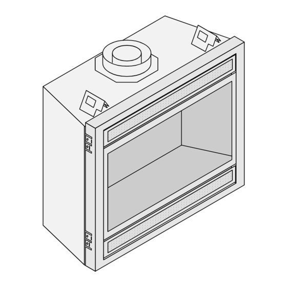
Page 6: Features And Specifications
8" (203mm) Diameter Vent 33-1/4" 845mm 31-3/4" 794mm 30-1/4" 768mm 28-3/4" 730mm 18-3/4" 32-1/2" 476mm 826mm 1" 25mm 30"* 762mm 24-1/4" 616mm 36-1/4" 921mm Weight: 155 Lbs. (70.4kg) 16-1/4"* 413mm * Includes the required 1/2" (13mm) clearance. Travis Industries 4081126 100-01210_000... -
Page 7: Installation
• Install the drywall. • Install the hearth (if applicable). • Install the facing (if applicable). • Install the mantel (if applicable). • Finalize the installation (see page 44) and install the grill or face. © Travis Industries 4081126 100-01210_000... -
Page 8: Massachusetts Requirements
A copy of all installation instructions for all Product Approved side wall horizontally vented gas fueled equipment, all venting instructions, all parts lists for venting instructions, and/or all venting design instructions shall remain with the appliance or equipment at the completion of the installation. See Gas Connection section for additional Commonwealth of Massachusetts requirements. Travis Industries 4081126 100-01210_000... -
Page 9: Top Stand-Off Assembly
Make sure to follow the instructions below before BEFORE installing the fireplace. Standoff AFTER Bend the standoff in the numbered sequence shown above. Remove the screw below the standoff. Replace the screw to secure the standoff. © Travis Industries 4081126 100-01210_000... -
Page 10: Converting The Fireplace To Top Vent Configuration
Place the Remove the 4 screws securing the screws and assembly aside. intake cover plate. Place the screws and cover plate aside. Remove and discard the insulation found below the large cover plate. Travis Industries 4081126 100-01210_000... - Page 11 Verify the gasket on the outer flue assembly is in place, then attach it to the top of the fireplace using the screws removed earlier. © Travis Industries 4081126 100-01210_000...
-
Page 12: Fireplace Placement Requirements
Fireplace must be placed so the vents below and above the glass do not become blocked. Raised Fireplaces • The fireplace (and hearth, if desired) may be placed on a platform designed to support the fireplace (155 Lbs.70 Kg) and vent. Travis Industries 4081126 100-01210_000... -
Page 13: Min. Framing Dims. - Rear Vent Configuration
19-1/4" left rear of the 33-1/2" 489mm fireplace. 851mm 36-1/2" 927mm 16-1/2" 419mm The on/off switch/thermostat wire (if used) should be routed to a location near the right front of the fireplace. © Travis Industries 4081126 100-01210_000... -
Page 14: Min. Framing Dims. - Top Vent Configuration
WARNING: A cut-out for the gas line near the right front of the fireplace. may be required on the framing. See the dimensions under "Gas Line Connection" for details. Travis Industries 4081126 100-01210_000... -
Page 15: Nailing Brackets
90° Drywall (use a screwdriver if necessary). 5/8" (0.625mm) Drywall TOP VIEW Framing For installations using 5/8" (0.625mm) drywall Nailing Bracket Fireplace fold the shorter tab out 90° (use a screwdriver if Drywall necessary). © Travis Industries 4081126 100-01210_000... -
Page 16: Corner Installations - Rear Vent Configuration
Minimum 1" (25mm) Clearance Clearance 7" (178mm) Approximate (varies due to vent installation) NOTE: Most installations use: 6" (152mm) Section for 2x6 (51mm X 152mm) Walls 4" (102mm) Section for 2x4 (51mm X 102mm) Walls 44-1/2" Min. 1130mm Travis Industries 4081126 100-01210_000... -
Page 17: Corner Installations - Top Vent Configuration
(for qualified installers only) Corner Installations - Top Vent Configuration A typical 45° installation uses the framing dimensions shown in the illustration below (NOTE: all clearances still apply). Minimum 1/2" (13mm) Clearance 14-1/4" 362mm 44-1/2" Min. 1130mm © Travis Industries 4081126 100-01210_000... -
Page 18: Gas Line Requirements
The supply regulator (the regulator that attaches directly to the residence inlet or to the propane tank) should supply gas at the suggested input pressure listed above. Contact the local gas supplier if the regulator is at an improper pressure. Travis Industries 4081126 100-01210_000... - Page 19 The cover plate has a 7/8" (0.875mm) diameter hole (covered with a push plug). By rotating the plate 180° the hole may be re-located. You may also secure the plate in a customized location using the self-drilling screws. © Travis Industries 4081126 100-01210_000...
-
Page 20: Electrical Connection (Required)
The electrical line must be a min. 14 gauge, and supply 120 Volts at 60 Hz (2 Amps). Caution: Label all wires prior to disconnection when servicing controls. Wiring errors can cause improper and dangerous operation. Travis Industries 4081126 100-01210_000... -
Page 21: Optional Wall Switch Or Thermostat Installation
Green Green On/Off Switch White Caution: Label all wires prior to disconnection when servicing controls. Wiring errors can cause improper and dangerous operation. Note: When using a GreenSmart™ remote, use the receiver for on/off operation. © Travis Industries 4081126 100-01210_000... -
Page 22: Vent Requirements
• Failure to adjust the air shutter properly may lead to improper combustion which can create a safety hazard. Consult your dealer or installer if you suspect an improperly adjusted air shutter. Travis Industries 4081126 100-01210_000... -
Page 23: Approved Vent
If it does not, apply high temperature sealant to the joints of the affected sections. • Horizontal sections require a 1/4" (6mm) rise every 12" (305mm) of travel • Horizontal sections require non-combustible support every three feet (e.g.: plumbing tape) © Travis Industries 4081126 100-01210_000... -
Page 24: Approved Vent Configurations
(see the illustration below), and replace the screws. In this example, the restrictor is set in position # 3. (closed) #6 (open - stock position) # 0 Back of Firebox Travis Industries 4081126 100-01210_000... -
Page 25: Intake Restrictor Adjustment
Intake Restrictor Adjustment Position # 1 (open) 1/4" Socket Loosen the two screws holding the intake restrictor in place.. Position # 2 (closed) Slide the restrictor down to the lower position and tighten the screws. © Travis Industries 4081126 100-01210_000... -
Page 26: Diffuser Plate Adjustment
Bend the round portion of the diffuser so it is flat (position # 2). After (Position # 2) Secure the flattened diffuser plate with the screws removed earlier. Replace the exhaust restrictor (see “Exhaust Restrictor Adjustment” for restrictor settings). Travis Industries 4081126 100-01210_000... -
Page 27: Rear Vent Config. W Horizontal Term. (No Vertical Rise)
3 feet • Exhaust Restrictor # 0 (stock) 915mm • Intake Restrictor # 1 (stock) • Diffuser Position # 1 (stock) 0 feet • Min. 4" (102mm) Horizontal Section • Max. 24" (610mm) Horizontal Section(s) © Travis Industries 4081126 100-01210_000... -
Page 28: Rear Vent Config. W Horizontal Term. (W Vertical Rise)
(it does not matter both lengths of horizontal run whether it turns right or left). (Horizontal Length = H1 + H2). It may be a 90° or 45° elbow. This is considered a vertical elbow Travis Industries 4081126 100-01210_000... -
Page 29: Rear Vent Configuration With Vertical Termination
(it does not matter both lengths of horizontal run whether it turns right or left). (Horizontal Length = H1 + H2). It may be a 90° or 45° elbow. This is considered a vertical elbow © Travis Industries 4081126 100-01210_000... -
Page 30: Top Vent Configuration With Horizontal Termination
(it does not matter both lengths of horizontal run whether it turns right or left). (Horizontal Length = H1 + H2). It may be a 90° or 45° elbow. This is considered a vertical elbow Travis Industries 4081126 100-01210_000... -
Page 31: Top Vent Configuration With Vertical Termination
(it does not matter both lengths of horizontal run whether it turns right or left). (Horizontal Length = H1 + H2). It may be a 90° or 45° elbow. This is considered a vertical elbow © Travis Industries 4081126 100-01210_000... -
Page 32: Termination Requirements
NOTE: Measure clearances to the nearest edge of the exhaust hood. • Use the vinyl siding standoff when installing on an exterior with vinyl siding. • Vent termination must not be located where it will become plugged by snow or other material Travis Industries 4081126 100-01210_000... -
Page 33: Hearth Requirements
Raised A hearth is not required Fireplaces when the fireplace is raised above the flooring surface. Fireplace Stand © Travis Industries 4081126 100-01210_000... -
Page 34: Facing Requirements
If the fireplace is raised, drywall up to the bottom edge as well. Do not install drywall (or any other combustible) in front of the fireplace. TOP VIEW Framing Nailing Bracket Fireplace Drywall Travis Industries 4081126 100-01210_000... -
Page 35: Facing Overview
May fit over top of tile facing Victorian Lace 27-1/2” (699mm) 32-3/8” (822mm) Optional facing buttes to edge of faceplate (tile line) Bungalow, Tree of Life 27-1/2” (699mm) 32-3/8” (822mm) Optional facing buttes to edge of faceplate (tile line) © Travis Industries 4081126 100-01210_000... -
Page 36: Thin Facing Installation
FPX arched faces require the FPX Face Upgrade Kit (sku 98500683) and a triangular piece of facing in these upper corners. See the instructions included with the face for further 7-1/2" details. 191mm 1” 1-5/8" 32-1/2" 1-7/8" 41mm 826mm 48mm Travis Industries 4081126 100-01210_000... - Page 37 Tile or other facing under 1'' (25mm) thick. Face SIDE OF FIREPLACE Hearth: note how it extends under the face - max. 1'' (25mm) thick. The fireplace may be raised to accommodate thicker hearth materials. Max. 1'' (25mm) Floor © Travis Industries 4081126 100-01210_000...
-
Page 38: Thick Facing Installation
(or cement board, etc.) Masonry 1" NOTE: The nailing brackets are not used for this type 25mm 36-1/4" of installation - secure the fireplace to the floor with 921mm the brackets along the base of the fireplace. Travis Industries 4081126 100-01210_000... -
Page 39: Thick Facing Installation With Fpx Arched Faces
(98500683). This covers the (25mm) above the base of the upper corners. fireplace. FRONT VIEW 2-3/4" 70mm TOP VIEW Framing 29" 737mm Nailing Bracket 61" Radius (1549mm) Fireplace Drywall Face Masonry 1" 25mm 36-1/4" 921mm © Travis Industries 4081126 100-01210_000... - Page 40 Drywall Raised Fireplace (with no Hearth) Masonry or other non-combustible over 1'' (25mm) thick. SIDE OF FIREPLACE Face (Behind Masonry) The masonry extends 1'' (25mm) above the base of the fireplace. 1'' (25mm) Fireplace Support Floor Travis Industries 4081126 100-01210_000...
-
Page 41: Mantel Requirements
• A non-combustible SIDE OF FIREPLACE header must be used Non-Combustible Mantel (metal stud). Non-Combustible Facing © Travis Industries 4081126 100-01210_000... -
Page 42: Install Example - Build-Out (Dog-House) W Hor. Term
1/2'' (13mm) Clearance to Insulation require an insulated enclosure. sides and back of fireplace. NOTE: If required to use drywall inside the firebox enclosure, make sure to alter the framing accordingly. Vapor Barrier Drywall Optional Tile Travis Industries 4081126 100-01210_000... -
Page 43: Install Example - Build-In W Hor. Term
Top View NOTE: 1/2'' (13mm) Clearance to Insulation sides and back of fireplace. NOTE: If required to use drywall inside the firebox enclosure, make sure to alter the framing accordingly. Drywall Optional Tile © Travis Industries 4081126 100-01210_000... -
Page 44: Finalizing The Installation
Lift up and swing the lower grill down to acces the area below the Swing the concealment cover firebox. up and slide it back to expose AA Battery the controls. Holder AA Battery Tray Install the logs (see page 48). Travis Industries 4081126 100-01210_000... -
Page 45: Air Shutter Adjustment
(this is used primarily with brick faces). Acid wash (muriatic acid) is used to remove excess mortar. If not properly neutralized with an ammonia solution, the plated face may develop a permanent tarnish when the acid evaporates over time. Contact your dealer if uncertain your facing has been properly neutralized. © Travis Industries 4081126 100-01210_000... -
Page 46: Glass Frame Removal And Installation
Lift the glass frame slightly and attach the lower latches. NOTE: Make sure the glass frame is all the way in place - it should be flush with the front of the fireplace when installed. Travis Industries 4081126 100-01210_000... - Page 47 Top of Firebox Glass Frame Anchor Note how the washer on the latch fits behind the flange on the glass frame anchor. Once fully inserted, turn the latch until it is upright. © Travis Industries 4081126 100-01210_000...
-
Page 48: Log Set Installation
Finalizing the Installation (for qualified installers only) Log Set Installation Log Set Overview When installed, the logs should appear as shown below. Rear Log Right Twig Left Log Left Twig Right Log Travis Industries 4081126 100-01210_000... - Page 49 The rear log has a flat notch on both sides that center it on the grate. Place the rear log on the grate and slide it all the way back until the log contacts the end-brackets on the grate. © Travis Industries 4081126 100-01210_000...
- Page 50 (for qualified installers only) Right Log Installation The right log has a groove that fits over the grate. Note how the right side of the log rests on the burner but does not cover any burner holes. Travis Industries 4081126 100-01210_000...
- Page 51 (for qualified installers only) Left Log Installation The left log has a groove that fits over the grate. Note how the right side of the log rests on the burner but does not cover any burner holes. © Travis Industries 4081126 100-01210_000...
- Page 52 Finalizing the Installation (for qualified installers only) Left Twig Installation This hole fits over the pin on the rear log. The left twig should be positioned so the front edge contacts the grate as shown. Travis Industries 4081126 100-01210_000...
- Page 53 Finalizing the Installation (for qualified installers only) Right Twig Installation The right twig has two holes for the pins on the rear and right log. When in place the right twig will appear as shown above. © Travis Industries 4081126 100-01210_000...
- Page 54 Ember Installation A bag of embers is provided to further enhance the firebox. Place the embers on the firebox floor and on the burner. Do not place embers over any of the burner holes or air channels. Travis Industries 4081126 100-01210_000...
-
Page 55: Lp Conversion Instructions
Remove the glass (see page 44). Remove the logs and embers (if installed - page 48) Remove the burner (see illustration below). 1/4" Nutdriver Remove the grate. 1/4" Nutdriver Remove the front burner. 1/4" Nutdriver Remove the rear burner. © Travis Industries 4081126 100-01210_000... - Page 56 Orifice Use a 1/2" open end wrench to unscrew the two orifices. Look here for the orifice identification Front 15/16" Rear 24mm Screw each LP orifice in so the orifice protrudes 15/16" (24mm) (indicating full insertion). Travis Industries 4081126 100-01210_000...
- Page 57 T-20 Torx or Slotted Screwdriver Make the gas line connection, bleed the gas line (if applicable), start the heater and thoroughly leak- test all gas connections and the gas control valve. © Travis Industries 4081126 100-01210_000...
-
Page 58: Optional Equipment
“a” to secure Loosen this screw and slide the bracket up. Place the floor the side firebacks.. firebacks in place (under the bracket). Slide the bracket down and tighten the screw to secure the firebacks. Travis Industries 4081126 100-01210_000... -
Page 59: Grill Installation
(this prevents it allows the grill to swing bushing. Once in place the grill is the grill from accidentally falling off). forward. held in place by gravity. © Travis Industries 4081126 100-01210_000... -
Page 60: Installation Packing List
(2) #8 x ½” Machine Screws • (2) Wire Ties • Torx T-20 Wrench • Wall Mount (for placing the transmitter on a wall) • (2) Drywall anchors (for wall mount) • (2) #8 x 3/8” Type B Screws Travis Industries 4081126 100-01210_000... - Page 61 CONTROL SPARK ROD DIAGNOSTIC ADAPTER VALVE COMMAND POWER GROUND Green Orange POWER SUPPLY Yellow / Green IPI / CPI Black Green Blue White White Black CONTINUOUS PILOT BATTERY COMFORT MAIN BURNER TRAY GREENSMART CONTROL PILOT © Travis Industries 4081126 100-01210_000...
-
Page 62: Greensmart Wiring Diagram
Receiver IPI / CPI Blue White CONTINUOUS (4) AA Batteries PILOT 120 VAC Power In Fan Controller POWER GREENSMART 110V OUT AUX OUT PILOT Ground FAN CONTROL Accent Thermodisk Light (s) Optional Blower(s) Accent Light Rheostat Travis Industries 4081126 100-01210_000... - Page 63 Unscrew the four screws holding the control cover in place (see Figure 2). Carefully remove the control cover (see Figure 3) Figure 2 Figure 3 Unplug the ac adapter from the power harness (see Figure 4). You can leave the ac adapter plugged into the wiring harness. Figure 4 © Travis Industries 4081126 100-01210_000...
- Page 64 Disconnect the two leads on the back of the control panel for the IPI / CPI switch (continuous pilot / greensmart pilot – see Figure 6). Figure 6 Disconnect the comfort control valve connection (see Figure 7). Disconnect the burner control connector from the fireplace burner control (see Figure 8). Figure 7 Figure 8 Travis Industries 4081126 100-01210_000...
- Page 65 (see Figure 12). These items may be discarded. Figure 11 Figure 12 Use the included torx wrench to remove the stock regulator (see Figure 13). These items may be discarded. Figure 13 © Travis Industries 4081126 100-01210_000...
- Page 66 Place the GreenSmart wiring harness in front of the fireplace, noting the position of each connector (see .Figure 16). Figure 16 Attach the wiring harness to the burner control (see Figure 17). Attach the gas control valve molex connector (see Figure 18). Figure 17 Figure 18 Travis Industries 4081126 100-01210_000...
- Page 67 Place the fan controller near the front of the fireplace to the left and connect it to the wiring harness (see Figure 22). Attach the power cord from the fan controller to the AC connection (see Figure 23). MAKE SURE TO TURN THE FAN CONTROLLER ON (“-“ SYMBOL). Figure 23 Figure 22 © Travis Industries 4081126 100-01210_000...
- Page 68 Attach the included velcro to the bottom of the fan control module and to the base of the fireplace near back left of the fireplace. Slide the fan controller into place and secure using the velcro (see Figure 26). Figure 26 Travis Industries 4081126 100-01210_000...
- Page 69 – the receiver should beep 5 times – see the operating instructions for further details). Figure 30 Figure 29 Place the receiver coverplate (and switch) over the receiver (see Figure 31) and attach with the two screws included with the receiver (see Figure 32) © Travis Industries 4081126 100-01210_000...
- Page 70 Use the included drywall anchors (and screws) to secure it to the wall (see Figure 35). Figure 35 Restore power to the fireplace and test operation of the remote (see the instructions included with the remote). Travis Industries 4081126 100-01210_000...
- Page 71 Optional Equipment (for qualified installers only) © Travis Industries 4081126 100-01210_000...
-
Page 72: Index Index
Installation Example - Build-In with Horizontal Termination ....43 Installation Options ............6 Installation Overview ............ 7 Intake Restrictor Adjustment ........25 Listing Details ............... 2 Log Set Installation ............48 LP Conversion Instructions .......... 55 Mantel Requirements ........... 41 Travis Industries 4081126 100-01210_000...
Need help?
Do you have a question about the GreenSmart 564 SS and is the answer not in the manual?
Questions and answers