
Related Manuals for SystemAir AXS Series


Summary of Contents for SystemAir AXS Series
- Page 1 Axial fans/Jet fans AXC, AXCBF, AXR, AXS, AJR, AJ8 Installation and Operating Instructions Document in original language | · 014...
- Page 2 © Copyright Systemair AB All rights reserved E&OE Systemair AB reserves the rights to alter their products without notice. This also applies to products already ordered, as long as it does not affect the previously agreed specifications. | 014...
-
Page 3: Table Of Contents
Contents General information .........1 7.2.5 Air gap........20 Installation jet fans ....... 21 Warning symbols ........1 7.3.1 Deflector ........ 21 1.1.1 Instruction symbols.....1 Electrical connection ........21 Important safety information ......1 Protecting the motor......21 Personnel ..........2 Connection ......... 22 Personal protective equipment....2 8.2.1 Terminal box ...... -
Page 5: General Information
♦ Abide by the system-related conditions and requirements of the system manufacturer or plant constructor. ♦ Safety elements may not be dismantled, circumvented or deactivated. ♦ Only use the fan in operational condition, if in doubt contact Systemair. ♦ Provide generally prescribed electrical and mechanical protective devices. -
Page 6: Personnel
Further prerequisites are a completed maintenance plan with no gaps and a commis- sioning report. Systemair will require these in the case of a warranty claim. The commissioning report is a component of this document. The maintenance plan must be created by the operator, see section 11.2 Maintenance. -
Page 7: Delivery
Storage more than 12 months ♦ Turn the impeller at least 10 revolutions once a ♦ We recommend an inspection by the after-sales month. service of Systemair before commissioning. ♦ Please ensure that the impeller is at a different position afterwards. | 014... -
Page 8: Description
| Description Description General • The fan conveys air in an axial direction from the intake side via the electric motor to the outlet side. (except AXCBF). • The electrical connection is made through a terminal box installed on the outside of the housing (except AXCBF). Sensors (optional) Sensors can be connected to the fan to monitor the roller bearings and for vibration monitoring. -
Page 9: Air Gap Between Housing And Impeller
Description | 5.1.3 Air gap between housing and impeller AXC (K) AXC (B) AXR (K) AXC (K)-P AXC (F) AXC-P AXR (B) AXC (B)-P AXR (F) AXC (F)-P AXC-PV AJR (K) AXC (K)-PV AJR (F) AXC (F)-PV AXC-H AJR (B) AXC (B)-PV AJ8 (F) AJ8 (K) -
Page 10: Construction Axc
| Description 5.2.1 Construction AXC Motor Terminal box Mounting feet Housing Impeller Motor brackets Guide vane only available for -PV version 5.2.2 Construction AXC-H Hub cover Terminal box Motor Impeller Housing with integratet guide vane | 014... -
Page 11: Types & Variants
Description | 5.2.3 Types & variants Table 3 Axial fan base types Type Description Standard fan of the AXC-series. As a default, the fans are provided in protection class IP55, ISO F. Special fans for marine, oil and gas applications. The conveying direction can be reversed by switching the direction of rotation. -
Page 12: Accessories
Note: • Some accessories are also available for jet fans and AXCBF, please check our online catalogue or contact Systemair. • *The distance between safeguard SG-20 and the impeller must be ≥ 120 mm according to ISO 13857. | 014... - Page 13 Description | Vertical installation | 014...
- Page 14 | Description | 014...
-
Page 15: Description Jet Fans
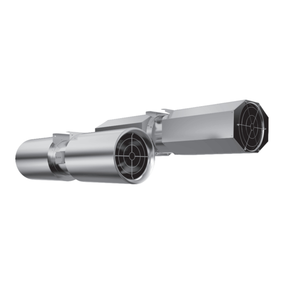
Description | Description Jet fans 5.3.1 Description AJR/AJ8 • In B3 conventional motors, the motor bracket is made from galvanized steel sheet. B30 “pad mounted” motors are fitted in the housing via threaded rods or a welded motor support. • The fan conveys air in an axial direction from the intake side via the electric motor to the outlet side. •... -
Page 16: Description Axcbf
| Description Table 6 Dimensions AJ8, AJR Size H [mm] B [mm] E [mm] F [mm] L [mm] 1535 AJ8 315 (B), (F) 1695 AJ8 355 (B), (F) 1875 AJ8 400 (B), (F) 1535 AJR 315 (B), (F) 1695 AJR 355 (B), (F) 1875 AJR 400 (B), (F) Description AXCBF... -
Page 17: Construction
Description | 5.4.1 Construction Motor Impeller Housing Motor bracket Table 7 Dimensions Size 250 — 500 Size 630 — 800 Size Ø B Ø C Ø D Ø F Ø H [mm] AXCBF 250 8x45° AXCBF 315 8x45° AXCBF 400 8x45°... -
Page 18: Intended Use
* A variable speed drive must be installed with this fan! This Powered Smoke and Heat Control ventilator shall be installed as per the manufacturer´s instruction. Installation and Operating Instructions are within the delivery. Systemair GmbH - Seehöfer Straße 45 - 97944 Boxberg - Germany | 014... -
Page 19: Installation
Installation | Table 8 Type key — /10° (-)(K), (B), (F) • C — counter-rotating • V — guide vane • G — Garage • A — Low pressure impeller • P — plus (new impeller generation) • H — High pressure fan Temperature- Time information (smoke extraction fan), see 5.1.2 Temperature types, page 4... -
Page 20: Vibration Dampers
Mounting feet Depending on the kind of fan and the construction size, mounting feet are either included in the delivery or available as accessories. If you are not sure, check the online catalogue or contact Systemair. Avoid resonance frequencies Important Risk of damage to the fan due to resonance frequencies ♦... - Page 21 Installation | Hexagonal head set screw Sylodyn anti Available as Systemair accessory with a hole Ø vibration block 16mm Safety plate Available as Systemair accessory with a hole Ø 16mm Hexagonal nut min. 15 mm Mounting foot Mounting frame Lifting and positioning The weight of the fan units varies depending on the motor size and accessories.
-
Page 22: Installation Positions
♦ Consider below guideline for installation positions. Note: • Order process (Systemair configurator): If the type of installation is e.g. "SO" (vertical installation, >= IEC 160), a suitable motor is automatically used (in this case with different bearings). • Please contact Systemair if a position marked with a “red-cross” is required for an existing fan. -
Page 23: Installation Of Flexible Connections
Installation | Distance from the wall/ceiling ♦ Ensure enough distance between the ceiling and the wall. • The duty point may not be reachable. • The fan may make noise. If the minimal distances are not possible for construction min. 1xD reasons, install a deflector in front of the fan in a way that ensures a direct, smooth and constant flow of air. -
Page 24: Installation Silencer
7.2.5 Air gap Ensure that the air gap between the housing and the impeller is complied with. ♦ Contact Systemair ♦ Do not install the fan if the gap in the table is not complied with. ♦ Check if the air gap complies with the table.5.1.3 Air... -
Page 25: Installation Jet Fans
Electrical connection | Installation jet fans Always install in a horizontal position. 7.3.1 Deflector For optimal guidance of the air current, a deflector made of galvanized steel sheet can be mounted on the pressure- side silencer (accessory). The deflector as accessory for AJR/AJ8 is delivered in a separate package. ♦... -
Page 26: Connection
| Electrical connection Important Damage to motor due to over temperature. ♦ To avoid too many starts and stops a falling delay time of minimum 5 minutes has to be realized in the control circuit. Table 10 Motor protection Type Motor protection Thermal protection, Speed regulation... -
Page 27: Terminal Box
Electrical connection | 8.2.1 Terminal box The below terminal boxes are used for fans up to a nominal current of 100 A. If the nominal current exceeds 100 A oth- er terminal boxes are used. • up to size* 900 •... -
Page 28: Frequency Converter (If Used)
♦ Operation at frequencies below 10Hz and above 60Hz must be avoided. ♦ Smoke extract axial fans should be operated at maximum mains frequency. If the mains frequency is to be exceeded in individual cases, please contact Systemair in advance. ♦ Starting time: min. 60 sec. -
Page 29: Commissioning Of Speed-Controlled Fans
The working point of the fan, as well as used external devices and accessories, also influence the running characteristics. Adjusting the blade angle If the working point of the fan has to be changed and it is necessary to adjust the blade angle, please contact Systemair! Operation Safety information Warning: Hazard from electrical voltage or moving components. -
Page 30: Troubleshooting/Maintenance/Repair
Remove the blockage blocked Check the cooling impeller (if used), measure the motor Motor overheated winding (if possible) / contact Systemair Thermal contacts/ Change direction of rotation (swap two phases in case of a 3– Impeller rotates in wrong resistors have phase motor) direction. -
Page 31: 11.2 Maintenance
Troubleshooting/maintenance/repair | Note: For all other damage/defects, please contact Systemair. Defective safety-relevant fans (for Ex and smoke extraction applications) must be replaced completely. 11.2 Maintenance Warranty claims can only be made if maintenance work is carried out correctly and written evidence thereof is provided. -
Page 32: 11.3 Variable-Speed Fans
5) Extension of maintenance intervals ♦ Systemair axial fans withoutVDD need to be maintained after a 20,000/40,000 hours of operation (depending on the type of motor bearing) or at the latest after 5 years. ♦ The maintenance intervals can be prolonged using VDD, as shown in the table below. -
Page 33: 11.5 Spare Parts
Cleaning | 11.5 Spare parts ♦ Use original spare parts from Systemair only. ♦ When ordering spare parts, please specify the serial number of the fan. This can be found on the name plate. Cleaning Safety information ♦ Cleaning may only be carried out by adequately qualified persons, details see Table 1 Qualifications, page 2. -
Page 34: Commissioning Report
| Commissioning Report Commissioning Report Warranty claims can only be made if commissioning work is carried out correctly and written evidence thereof is provided. Description: Article no.: Manufacturing order no.: Installer Company: Contact person: Company address: Tel. no.: Email: Operator (Place of installation) Company: Contact person: Company address:... - Page 35 Commissioning Report | Measured data at commissioning Voltage [V]: Temp. of transported air [°C]: Fan impeller speed [rpm]: Current L1 [A]*: Current L2 [A]: “Air volume”, “Differential pressure” not necessary for Jet fans Current L3 [A]: Air volume [m3/s]: *For single-phase fans, fill in line “Current L1 [A]” Differential pressure [Pa]*: *Δ- Pressure between suction-side and discharge of the fan If an air flow measurement is not possible, this value can be calculated using the following formula:...
- Page 36 Systemair GmbH Seehöfer Str. 45 97944 Boxberg Germany Tel.: +49 (0)7930/9272-0 Fax: +49 (0)7930/9273-92 info@systemair.de www.systemair.de...
Need help?
Do you have a question about the AXS Series and is the answer not in the manual?
Questions and answers