Advertisement
Quick Links
Advertisement

Related Manuals for real living FP-P-1915-32


Summary of Contents for real living FP-P-1915-32
-
Page 2: Maintenance
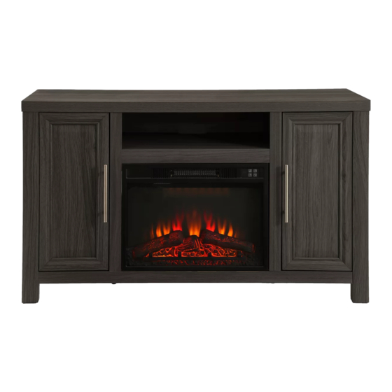
GENERAL BEST PRACTICES FOR ASSEMBLY Read all instructions before starting Clear a flat covered space to begin We recommend 2 adults for assembly Note that hardware required is provided for every step Pay attention to orientation Letter of the part corresponds to a sticker on the product Number of the hardware corresponds to its number in the package Helpful hints provided along the way WARNINGS... - Page 3 CAUTION This Fireplace (FP-P-1915-32) is designed for flat panel LCD TVs weighing up to 60 lbs. For items other than flat panel LCD TVs, this fireplace will support up to 135 lbs when the item is placed evenly on the top surface. Use with other products may results in instability causing possible injury.
-
Page 4: Part List
PART LIST LEFT SIDE PANEL MIDDLE SHELF BASE 2PCS RIGHT SIDE PANEL LEFT PARTITION RIGHT PARTITION SIDE TRIM 4PCS SMALL SHELF POST A POST B POST C 2PCS 2PCS POST D DOOR SIDE BACK PANEL MIDDLE BACK PANEL 2PCS INSERT FIREPLACE MIDDLE LEG HEATER... -
Page 5: Hardware List
HARDWARE LIST 33pcs 33pcs 29pcs 2pcs CAM BOLT CAM LOCK WOOD DOWEL HANDLE 5pcs 33pcs 5pcs 2pcs BOLT ROUND HEAD SCREW ROUND HEAD SCREW DOOR BLOCK 17pcs 4pcs 25pcs 5pcs SHELF PIN DOOR HINGE SHORT FLAT HEAD LONG FLAT HEAD SCREW SCREW 21pcs... -
Page 6: Helpful Hints
HELPFUL HINTS RING SHOULD TOUCH THE BOARD Screw the cam bolt into the predrilled panel. The cam bolt should be tightened so no threads are visible. The larger ring of the cam should touch the panel. Insert the cam lock into the predrilled hole in the panel. Arrow faces the outside of the panel. - Page 7 STEP 1 Place Post A (J), Post B (K), Post C (L) and Post D (M) on a soft smooth surface. The side with the most holes should be facing up. Insert the Cam bolt (H1) into the corresponding hole of Post A (J), Post B (K), Post C (L) and Post D (M) using the screwdriver (Not provided).
- Page 8 STEP 3 Place Right side panel (E) on a soft smooth surface with the holes facing up. Insert the Cam Bolts (H1) and Wood dowels (H3) of Post C (L) and Post D (M) into the corresponding holes of Right side panel (E) and secure in place using Cam lock (H2) as shown in figure 3.
- Page 9 STEP 5 With assistance from another adult, hold Middle shelf (B) and Left partition (G) vertically as shown in figure 5. Insert Wood dowels (H3) into the corresponding holes of Middle shelf (B) as shown in figure 5. Slide the Cam bolts (H1) of Left partition (G) into the corresponding holes of Middle shelf (B) and secure in place with Cam lock (H2) using screwdriver (Not provided).
- Page 10 STEP 7 With assistance from another adult, place Left side panel (D) on edge as shown in figure 7. Align the holes in Left partition (G) and Right partition (H) with the Cam bolts (H1) in Base (C) and slide into place as shown in figure 7.
- Page 11 STEP 9 Place Top (A) on a soft smooth surface with the holes facing up. Insert Cam bolt (H1) into the indicated holes in figure 9 and fully tighten using the screwdriver (Not provided). Figure 9 Not provided 8pcs Assembled View: STEP 10 With assistance from another adult, align the Cam bolts (H1) in Top (A) with the holes in Left side panel (D), Left partition (G), Right partition (H) and Right side panel (E) and slide into place as shown in figure...
- Page 12 STEP 11 With assistance from another adult, carefully tip the assemble pieces upright as shown in figure 11. Figure 11 STEP 12 Place The Door (N) on a soft smooth surface with the large holes facing up. Align the holes of Door hinge (H10) with the pre-drilled holes of The Door (N) as shown in figure 12. Secure Door Hinge (H10) in place with Short flat head screw (H11) using screwdriver (Not provided) as shown in figure 12.
- Page 13 STEP 13 With assistance from another adult, hold The Door (N) vertically and attach Handle (H4) to the middle of the door with Bolt (H5) using screwdriver (Not provided) as shown in figure 13. Repeat these same steps for another Door (N) 2pcs 4pcs Figure 13...
- Page 14 STEP 15 Align the holes in Side back panel (O) with the pilot holes in Top (A) and secure to Top (A), Left side panel (D), Left partition (G), Right partition (H), Right side panel (E) and Base (C) with Round head screw (H6) using screwdriver (Not provided) as shown in figure 15.
- Page 15 STEP 17 Cover any visible Cam lock (H2) using Sticker (H14) as shown in figure 17. Figure 17 STEP 18 Wood Mantel assembly is completed. Note: Please read the instruction booklet for the assembly and function Insert Fireplace Heater and remote control before using Fireplace Adjust the leveler on Middle leg (Q) flush...
- Page 16 STEP 19 Install the Anti-Tip Hardware (H15) to secure the stand to the wall and prevent top over. Install one bracket to each top back middle of the Console Fireplace. Place the stand in the desired location and mark where the installed bracket meet the wall. Remove the stand and using the remaining bracket.
Need help?
Do you have a question about the FP-P-1915-32 and is the answer not in the manual?
Questions and answers