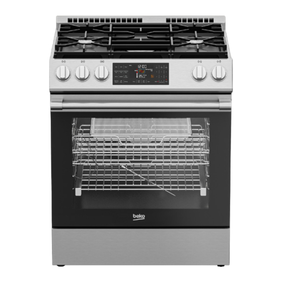
Beko SLDF 30524SS Owner's Manual
30" slide-in dual fuel range
Hide thumbs
Also See for SLDF 30524SS:
- Safety & installation instructions (32 pages) ,
- Owner's manual (32 pages)

Related Manuals for Beko SLDF 30524SS


Summary of Contents for Beko SLDF 30524SS
- Page 1 30" Slide-In Dual Fuel Range Owner’s Manual SLDF 30524SS 285.6003.26 / R.AA/ 12.06.2023...
- Page 2 Store / Dealer City State Zip Code If you have questions or comments, please contact your local authorized Beko dealer, or call our Toll Free Customer Hotline number. 1-888-352 BEKO (2356) BEKO.COM/US-EN To register your product with Beko, please go to...
-
Page 3: Table Of Contents
Control Panel Overview ......................... 8 Preparation ............................10 Settings............................11 Operation ............................13 Care and Maintenance ........................26 Troubleshooting ..........................29 Warranty and Service ........................30 FURTHER INFORMATION Browse the Beko website for helpful information on using your slide-in range, care and maintenance, troubleshooting and more just visit http://www.beko.us... -
Page 4: Premium Technology
PREMIUM TECHNOLOGY At Beko, we believe a truly revolutionary product is one that redefines what is possible in terms of performance. Secondly, it must achieve that performance while using the least amount of natural resources possible. And finally, it needs to be priced within reach of everyone who wants to lead a healthy and sustainable life. -
Page 5: Technical Information
TECHNICAL INFORMATION General Overall Height 36" (914 mm) Overall Width 29 - 13/16" (757 mm) Overall Depth 28 - 3/4" (730 mm) Total electric power 4 kW Electrical connection 120/240 V~;60 Hz 2AC~N Cable type / Cross section / Fuse SJT 3x18 / AWG / max. -
Page 6: Slide-In Range Overview
SLIDE-IN RANGE OVERVIEW Control knobs Model / Serial Tag / Rating Label (Located on bottom of control panel) Warming Drawer Foot... - Page 7 SLIDE-IN RANGE OVERVIEW Splashback Burners Control panel Handle Front door...
-
Page 8: Control Panel Overview
CONTROL PANEL OVERVIEW Display The selected functions are shown here as well as the current oven operating conditions. Burner Indicator Light Burner Control Knobs These knobs are used to turn on and adjust burner temperatures. - Page 9 Numeric Keypad This section is used to enter temperature, time, start and stop cooking modes. Start / Cancel Keys These keys are used to start and cancel cooking modes.
-
Page 10: Preparation
PREPARATION INITIAL HEATING The following information will help you to use your appliance in an ecological way, and to save energy. • Heat up the product for about 30 minutes and then switch it off. Thus, any production residues or layers will be TIPS FOR SAVING ENERGY burnt off and removed. -
Page 11: Settings
SETTINGS Warning: Before using the oven, the 24 Hour 12 Hour 24 Hour 12 Hour clock must be set. If the clock is not set, the oven some functions will not 10:00 10:00 AM 22:00 10:00 PM work properly. 11:00 11:00 AM 23:00 11:00 PM... - Page 12 SETTINGS with water! When oil catches fire, cover it with a fire blanket. Turn off the hob if it is safe to do so and call the fire department. Warning: Never extend the flame beyond the outer edge of the cooking utensil.
-
Page 13: Operation
OPERATION BURNERS • Use flat bottomed saucepans or vessels Igniting the gas burners only. • Gas burners are controlled with gas hob • Put appropriate amount of food in sauce- knobs). pans and pans. Thus, you will not have to make any unnecessary cleaning by prevent-ing the dishes from overflowing. - Page 14 OPERATION OVEN 59 minutes. If a value greater than 5:59 is set, the clock will return an error. CANCEL AN ALARM 1. To cancel an alarm after it has been set, press “Timer” on the touchpad. TIMER • The oven timer can be used as a warning or reminder and operates separately from the oven functions.
- Page 15 OPERATION OVEN 3. For cooking time, press the 'Cook Time' key once. Enter the cooking time using numbers on the right keypad while Cook and Time are flashing. 4. Press “Cook Time” key once to set the cooking time. Enter how long you wish program to last, using the numbers •...
- Page 16 OPERATION OVEN COOKING TIPS Cooking Vegetables • Cook vegetables in a pan with a lid to Baking keep them from running out of liquid and drying out. • Use dark-colored or -enamel coated cookware to improve heat transfer. • Boil vegetables before cooking in the oven to make sure they cook fully.
- Page 17 OPERATION OVEN OVEN FUNCTION MODES Convection Bake Bake For best results, preheat oven when For best results, preheat oven when using bake mode. using bake mode. Heat radiates from the bake Heat radiates from the bake element, situated at the bottom of element, situated at the bottom of the oven cavity.
- Page 18 OPERATION OVEN Broil touchpad, and press the Start key. To cancel the cycle, press the “Clear Off” For best results, preheat oven for 5 to key. 6 minutes when using the broil mode. Turn items once while cooking. Broiling Roast time will vary based on size, weight, For best results, preheat oven when thickness, starting temperature, and...
- Page 19 OPERATION OVEN Pizza booster is not active. This oven function is available by Booster cannot be selected in Warm pressing “More Functions” on the Keep, Sabbath and Self Clean. touchpad until the function illuminates If you set the temperature below 500 on the display.
- Page 20 OPERATION OVEN Bread Proof Warming Drawer Warning: The warming drawer will keep Only bottom heat is on. The bread proof hot, cooked foods at serving temperature. mode can be used leavening of the Always start with hot food. Cold or room bread and pizza dough or other yeast temperature foods cannot be heated or dough.
- Page 21 OPERATION OVEN AirFry Warning: Airfry accessories should only be used with the airfry function. When the Airfry accessory is used with functions where the oven burners work (bake, convection bake, roast, convection roast, etc.), oil falling off the accessory may cause smoke and fire in the oven due to the heat.
- Page 22 OPERATION OVEN Doing so blocks airflow through the Place a proper size(larger than AirFry oven and can result in carbon monoxide tray) baking sheet or tray on the rack poisoning. Aluminum foil can also trap below the AirFry tray to catch any heat, causing a fire hazard or poor oven drippings from food.
- Page 23 OPERATION OVEN Using the Meat Probe "Probe" appears on the display of the oven when the probe is attached to its slot on the The probe is used to measure the side wall of the chassis. It can be used with central temperature of meats and the Probe;...
- Page 24 OPERATION SUGGESTED BAKE/ROAST TIMES CHART Number of Food Cooking Mode Oven Temp. Rack Position Racks Sponge cake Bake 350 °F ( 175 °C) Single Sponge cake Convection Bake 300 °F ( 150 °C) Multiple 3 and 5 Loaf (leavened) Bake 400 °F ( 205 °C) Single Loaf (leavened)
- Page 25 OPERATION SUGGESTED BAKE/ROAST TIMES CHART Pan Size and Time(min.) Explanation Type 8" (200mm) or 9" The cakes are positioned in the middle of the oven. Bake foods with 25 - 35 (230mm) round 1" (25 mm) - 1.5" (38 mm) space between pans and oven wall. 8"...
-
Page 26: Care And Maintenance
CARE AND MAINTENANCE SELF CLEANING FUNCTION Warning: Do not clean the door gasket. Fiberglass gasket is highly sensitive and can get damaged easily. In case Warning: If the oven is hot, self cleaning of a damage on the oven door gasket, mode cannot be operated until the replace with the new one from the oven is cold. - Page 27 CARE AND MAINTENANCE force door open or closed the hinge could Caution: During the Self-Cleaning cycle, be damaged and injury could result. the electrical flow to hob burners will be cut. After turning the function and • Do not lay removed door on sharp or thermostat knob to off position, the pointed objects as this could break the door lock will be automatically opened.
- Page 28 CARE AND MAINTENANCE REPLACING THE OVEN LAMP Caution: The lamp used in this appliance is not suitable for household room illumination. The intended Warning: Hot surfaces cause burns! purpose of this lamp is to assist the Before replacing the oven lamp, make user to see food stuffs.
-
Page 29: Troubleshooting
TROUBLESHOOTING OVEN LIGHTS DO NOT TURN Warning: Consult your Authorized Service Agent or the dealer where you purchased the product if the instruction above do not remedy • Defective oven light bulb. >>>Replace your issue. Never attempt to repair a bulb. -
Page 30: Warranty And Service
WARRANTY AND SERVICE The warranties provided by Beko in these statements only apply to Beko ranges sold to the original purchaser or homeowner in the US and Canada. The warranty is not transferable. To obtain warranty service, please contact our nearest distributor as listed by state and province. - Page 31 No Other Warranties. This Warranty Statement is the complete and exclusive warranty from the manufacturer. No employee of Beko or any other party is authorized to make any warranty statements in addition to those made in this Warranty Statement.
- Page 32 1-888-352 BEKO (2356) beko.com/us-en ©2022 Beko U.S., Inc. All rights reserved.
- Page 33 Safety & Installation Instructions WARNING: Read all safety instructions before using the product. If the information in this manual is not followed exactly, a fire or explosion may result causing property damage, personal injury or death. SLDF 30524SS 285.6003.27 / R.AA / 13.06.2023...
- Page 34 TO PREVENT TIPPING: If the information in this manual is not followed exactly, a fire or explosion may result causing property damage, personal injury or death. DO NOT OPERATE THE RANGE WITHOUT ANTI-TIP DEVICE IN PLACE AND ENGAGED This appliance is intended for normal household use only. It is not approved for outdoor or other non-household uses (including sea or air-going vessels).
- Page 35 PLEASE READ THESE INSTRUCTIONS CAREFULLY BEFORE INSTALLATION OR USING YOUR APPLIANCE ! SAVE THESE INSTRUCTIONS Save these instructions for the local electrical inspectors use. This product can only be used in the rooms which incorporates a properly adjusted and functioning Carbon Monoxide sensor. Make sure the Carbon Monoxide sensor works properly and its maintenance done frequently.
-
Page 36: Technical Information
TECHNICAL INFORMATION General Overall Height 36" (914 mm) Overall Width 29 - 13/16" (757 mm) Overall Depth 28 - 3/4" (730 mm) Total electric power 4 kW Electrical connection 120/240 V~;60 Hz 2AC~N Cable type / Cross section / Fuse SJT 3x18 / AWG / max. -
Page 37: Important Safety Information
IMPORTANT SAFETY INFORMATION Be sure to observe all listed warnings Warning: Never use your appliance for and cautions. Look particularly for the warming or heating the room. icons with exclamation marks inside. The information icon will also provide • User Servicing - DO NOT repair or important references. - Page 38 IMPORTANT SAFETY INFORMATION the rear surface; otherwise, connections Warning: Utensil handles should be can get damaged. turned inward and not extend over adjacent surface units - to reduce the Warning: Only use the connection risk of burns, ignition of flammable cable specified in the “Technical materials, and spillage due to specifications”.
- Page 39 IMPORTANT SAFETY INFORMATION with any kind of cover. Use only cooking to the oven bottom finish do not line utensils with recommended diameters. the oven bottom with any type of foil or Make sure ventilation and oven fume liner. outlets shown below are not closed. Warning: Do not cook on broken Otherwise fire hazard can occur.
- Page 40 IMPORTANT SAFETY INFORMATION cause burns among these surfaces are and free from combustible materials, oven vent openings and surfaces near gasoline, and other flammable vapors. these openings, interior surfaces of the Warning: Do Not Use Water on Grease oven cavity, oven doors, and window. Fires Smother fire or flame or use dry •...
- Page 41 IMPORTANT SAFETY INFORMATION breakage. Do not cook on a product Warning: Keep all ventilation slots clear with broken glass. Shock, fire or cuts of obstructions. may occur. • Only authorized replacement parts Warning: The manufacturer declines all may be used in performing service liability for injury to persons or damage on the range.
- Page 42 IMPORTANT SAFETY INFORMATION • Accessible parts may be hot when the • Do not operate the appliance barefooted. broil is in use. Young children should be • Never touch the appliance with wet kept away. hands or feet. • Surface units may be hot even though SAFETY FOR GAS they are dark in color.
- Page 43 IMPORTANT SAFETY INFORMATION ventilation device (mechanical extractor area where it started. hood). Prolonged intensive use of • The fire department is being called. the appliance may call for additional ventilation, for example increasing • The fire does not obstruct your escape the level of the mechanical ventilation route.
- Page 44 IMPORTANT SAFETY INFORMATION not harmful to the environment. Please • If an appliance hood is to befitted, refer dispose of all parts of the packaging to the manufacturer's instructions according to environmental standards. regarding fixing heights. • This is beneficial to the environment. •...
- Page 45 IMPORTANT SAFETY INFORMATION CLEARANCES & DIMENSIONS potential scratches during the lifting process. It is also recommended to take off watches and jewelry and to Caution: Dimensions that are shown in wear work shoes during installation for figure must be used. Given dimensions foot protection.
-
Page 46: Installation
INSTALLATION Warning: Do not install the range over carpeting unless you place an insulating pad or sheet of 1/44 inch (0.64cm) thick plywood between the unit and carpeting. ANTI-TIP STABILITY DEVICE INSTALLATION INSTRUCTIONS Warning: Verify the anti-tip device has been properly installed and engaged. •... - Page 47 INSTALLATION...
- Page 48 INSTALLATION ANTI-TIP STABILITY DEVICE Bracket Installation Option 2 INSTALLATION INSTRUCTIONS 1. Adjust your oven feets according to your counter. 2. Measure the dimension ‘A’ in Figure 3 . Warning: Verify the anti-tip device has been properly installed and engaged. 3. Mount the bracket to the wall as •...
- Page 49 INSTALLATION...
- Page 50 INSTALLATION HOW TO MOVE THE APPLIANCE Warning: Electrical shock hazard! Use extreme caution when drilling holes into the wall or floor. There may Movement of your appliance is most be concealed electrical wires located easily achieved by lifting the front as behind the wall or under the floor.
- Page 51 INSTALLATION CONNECTION TO THE MAIN Observe all governing codes and local SUPPLY ordinances • A 3 wire or 4 wire single phase 120/240 or 120/208 Volt, 60 Hz AC only electrical Warning: Electrical shock hazard! supply is required on a separate circuit Electrical installation must comply with fused on both sides of the line (red and national and local codes.
- Page 52 INSTALLATION • Amper cord is used it must be marked 3 & 4 -wire electrical wall receptacle for use with a 1 3/8 inches (35 mm) types & recommended mounting diameter opening. Cord must have either orientation on wall 3 or 4 conductors to match electric receptacle (Use copper or Aluminum •...
- Page 53 INSTALLATION Power cord strain relief installation • Purchase a strain relief before installation. 1. Using the 1-1/8 in. or 7/8 in. diameter opening insert the strain relief and power cord through the opening and secure the strain relief as directed in this instructions.
- Page 54 INSTALLATION Conduit Installation 3 & 4-wire permanent wire connections • Purchase a squeeze connector Warning: For 3-wire permanent matching the diameter of the conduit connection read carefully and follow and assemble it in the hole. Insert the steps 2 and 5 below. conduit through the squeeze connector Warning: For 4-wire permanent and tighten.
- Page 55 INSTALLATION 3 wire connection figure 4 wire connection figure 1. Terminal block 1. Terminal block 2. Squeeze connector 2. Squeeze connector 3. Washer 3. Washer 4. Nut 4. Nut 5. Grounding screw 5. Grounding screw BK. Black BK. Black WH. White WH.
- Page 56 INSTALLATION CONNECTION TO THE GAS Warning: THE CONVERSION SUPPLY HALL BE CARRIED OUT BY A MANUFACTURER'S AUTHORIZED REPRESENTATIVE, IN ACCORDANCE Warning: This appliance has been WITH THE REQUIREMENTS OF THE tested in accordance with the following MANUFACTURER, PROVINCIAL, OR standards: TERRITORIAL AUTHORITIES HAVING JURISDICTION AND IN ACCORDANCE •...
- Page 57 INSTALLATION 1. Install male 1/2" flare adaptor at the Rigid Pipe Method 1/2" NPT internal thread of the range • The configuration of the rigid pipe inlet. Use a backup wrench on the elbow connection will vary depending on the fitting to avoid damage.
- Page 58 INSTALLATION TEST FOR GAS LEAKS to L.O. Verify that the flame completely surrounds the burner. There should be a flame at each burner port and there Warning: Never check for leaks with a should be no air gap between the flame flame.
- Page 59 INSTALLATION • The California Safe Drinking Water and • Prolonged intensive use of the appliance may call for additional ventilation, for Toxic Enforcement Act requires the example the opening of a window, or Governor of Cali-fornia to publish a list the use of permanent fixed mechanical of substances known to the State of ventilation system for example, an...
-
Page 60: Package Contents And Accessories
PACKAGE CONTENTS AND ACCESSORIES HEIGHT-ADJUSTABLE Accessories supplied can vary depending on the product model. Not TELESCOPIC ROLLER-RACK every accessory described in the user WITH WIRE SHELF manual may exist on your product. • Used for roasting and for easily placing the food to be baked, roasted or cooked OWNER'S MANUAL in casserole dishes to the desired rack. - Page 61 PACKAGE CONTENTS AND ACCESSORIES How to remove the wire shelf with How to reattach the wire shelf with telescopic roller-rack telescopic roller-rack • You can remove the wire self with • To reattach the wire self with telescopic telescopic rails by first lifting it up and rails, the procedures applied when then pulling it towards you.
- Page 62 PACKAGE CONTENTS AND ACCESSORIES AIRFRY ACCESORIES How to clean the airfry accessories You can wash the basket part of How to set your range for AirFry the frying grill in the dishwasher. Intensive wash in the lower basket of 1. Place your AirFry tray recommended the dishwasher is recommended for rack positon 3 as shown picture1 and the basket.
- Page 63 NOTES...
- Page 64 1-888-352 BEKO (2356) beko.com/us-en ©2022 Beko U.S., Inc. All rights reserved.
Need help?
Do you have a question about the SLDF 30524SS and is the answer not in the manual?
Questions and answers