Advertisement
Quick Links
Owner's Manual & Safety Instructions
Save This Manual
operating, inspection, maintenance and cleaning procedures. Write the product's serial number in the
back of the manual (or month and year of purchase if product has no number). Keep this manual and the
receipt in a safe and dry place for future reference.
Email our technical support at: productsupport@harborfreight.com
When unpacking, make sure that the product is intact
and undamaged. If any parts are missing or broken,
please call 1-888-866-5797 as soon as possible.
©
Copyright
2022 by Harbor Freight Tools
No portion of this manual or any artwork contained herein may be reproduced in
any shape or form without the express written consent of Harbor Freight Tools.
Diagrams within this manual may not be drawn proportionally. Due to continuing
improvements, actual product may differ slightly from the product described herein.
Tools required for assembly and service may not be included.
Keep this manual for the safety warnings and precautions, assembly,
Visit our website at: http://www.harborfreight.com
®
. All rights reserved.
Read this material before using this product.
Failure to do so can result in serious injury.
SAVE THIS MANUAL.
22h
Advertisement

Related Manuals for Bauer 21221E-B


Summary of Contents for Bauer 21221E-B
- Page 1 Owner’s Manual & Safety Instructions Save This Manual Keep this manual for the safety warnings and precautions, assembly, operating, inspection, maintenance and cleaning procedures. Write the product’s serial number in the back of the manual (or month and year of purchase if product has no number). Keep this manual and the receipt in a safe and dry place for future reference.
-
Page 2: Table Of Contents
Table of contents Important Safety Information ...... 2 Maintenance and Servicing ....... 12 Specifications ..........5 Parts List and Diagram ......14 Setup - Before Use ........5 Warranty ............ 16 Operating Instructions ........ 8 WARNING SyMBOLS AND DEFINITIONS This is the safety alert symbol. It is used to alert you to potential personal injury hazards. - Page 3 General Tool Safety Warnings (continued) 10. WEAR PROPER APPAREL. Do not wear 17. USE RECOMMENDED ACCESSORIES. loose clothing, gloves, neckties, rings, bracelets, Consult the owner’s manual for recommended or other jewelry which may get caught in moving accessories. The use of improper accessories parts.
- Page 4 110-120 VAc Grounded Tools: Tools with Three prong plugs (cont.) 7. This tool is intended for use on a circuit that has an outlet that looks like the one illustrated above in 125 VAc 3-prong plug and Outlet. The tool has a grounding plug that looks like the plug illustrated above in 125 VAc 3-prong plug and Outlet.
- Page 5 Vibration Safety This tool vibrates during use. Repeated or 2. Do not smoke during use. Nicotine reduces long-term exposure to vibration may cause the blood supply to the hands and fingers, temporary or permanent physical injury, increasing the risk of vibration-related injury. particularly to the hands, arms and shoulders.
-
Page 6: Specifications
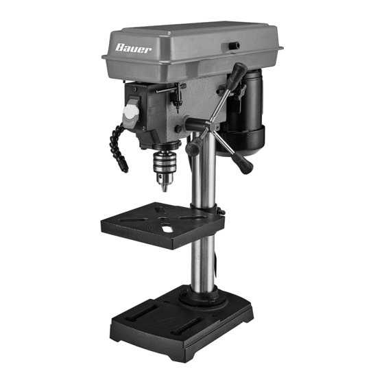
Specifications Electrical Rating 120VAC / 60 H z / 2.3 A 5 Speeds: 750, 1100, Spindle Speeds 1500, 2100, 3200 RPM Throat Depth 4″ (8″ Max Swing) Table Tilt 45º left and right Table Swing Around Column 360° Spindle Stroke 2″... - Page 7 Table to column Work Table (6) 1. Thread the Table Lock Handle (7) into the Table Support opening in the Table Support Bracket (5). Bracket (5) 2. Lower Table Support Bracket (5) down over the Column with the top of the table face up, and tighten Table Lock Handle to secure.
-
Page 8: Operating Instructions
Operating Instructions Read the ENTIRE IMpORTANT SAFETy INFORMATION section at the beginning of this manual including all text under subheadings therein before set up or use of this product. Tool Set Up TO pREVENT SERIOUS INJURy FROM AccIDENTAL OpERATION: Turn the power Switch of the tool off remove the Safety Key, and unplug the tool from its electrical outlet before performing any procedure in this section. - Page 9 changing Drill Speed Before changing drill speeds, make sure the 3. Consult the chart below and position the machine is switched OFF and UNPLUGGED. Belt on the Pulleys (37, 38) according to the desired drill speed. 1. Open the Pulley Cover. 4.
- Page 10 Workpiece and Work Area Set Up 1. Designate a work area that is clean and well-lit. 9. FOR FLAT WORK, lay the piece on to a The work area must not allow access by children wooden base and clamp it down firmly against or pets to prevent distraction and injury.
- Page 11 General Operating Instructions 1. Bring the drill bit down with the Feed Knob to where 6. To lock Drill Press in the OFF position, the hole is to be drilled. remove the safety key from Power Switch and Make minor workpiece alignment adjustments. store key in a safe place until next use.
-
Page 12: Maintenance And Servicing
Maintenance and Servicing procedures not specifically explained in this manual must be performed only by a qualified technician. TO pREVENT SERIOUS INJURy FROM AccIDENTAL OpERATION: Turn the power Switch of the tool off remove the Safety Key, and unplug the tool from its electrical outlet before performing any procedure in this section. - Page 13 Troubleshooting problem possible causes Likely Solutions Tool will not start. 1. Cord not connected. 1. Check that cord is plugged in. 2. No power at outlet. 2. Check power at outlet. If outlet is unpowered, turn off tool and check circuit breaker. If breaker is tripped, make sure circuit is right capacity for tool and circuit has no other loads.
-
Page 14: Parts List And Diagram
parts List and Diagram pLEASE READ THE FOLLOWING cAREFULLy THE MANUFACTURER AND/OR DISTRIBUTOR HAS PROVIDED THE PARTS LIST AND ASSEMBLY DIAGRAM IN THIS MANUAL AS A REFERENCE TOOL ONLY. NEITHER THE MANUFACTURER OR DISTRIBUTOR MAKES ANY REPRESENTATION OR WARRANTY OF ANY KIND TO THE BUYER THAT HE OR SHE IS QUALIFIED TO MAKE ANY REPAIRS TO THE PRODUCT, OR THAT HE OR SHE IS QUALIFIED TO REPLACE ANY PARTS OF THE PRODUCT. - Page 15 Assembly Diagram Record product’s Serial Number Here: Note: If product has no serial number, record month and year of purchase instead. Note: Some parts are listed and shown for illustration purposes only, and are not available individually as replacement parts. Specify UPC 193175446534 when ordering parts. Item 58780 For technical questions, please call 1-888-866-5797.
-
Page 16: Warranty
Limited 90 Day Warranty Harbor Freight Tools Co. makes every effort to assure that its products meet high quality and durability standards, and warrants to the original purchaser that this product is free from defects in materials and workmanship for the period of 90 days from the date of purchase.
Need help?
Do you have a question about the 21221E-B and is the answer not in the manual?
Questions and answers