
Subscribe to Our Youtube Channel
Related Manuals for Schmalz SCPSi-2


Summary of Contents for Schmalz SCPSi-2
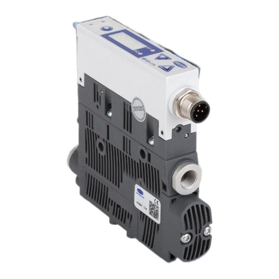
- Page 1 Innovative Vacuum for Automation Operating instructions SCPSi-2 30.30.01.00762 Eco-Nozzle Technology...
-
Page 2: Table Of Contents
SCPS CH MALZ ONTENTS Safety Instructions ....................1-5 Important symbols ..........................1-5 General safety instructions ....................... 1-5 Intended use ............................. 1-6 Installation and operation ......................... 1-7 Product Overview ....................2-8 General description of functions ...................... 2-8 Vacuum generation (picking up the workpiece) ................2-8 Blow-off (depositing the workpiece) .................... - Page 3 SCPS CH MALZ Autoset ............................3-29 Energy monitoring [EM] ........................3-30 Percentual air consumption measurement..................3-30 Absolute air consumption measurement ..................3-30 Energy consumption measurement ....................3-30 Predictive Maintenance [PM] ......................3-31 Measurement of the leakage ......................3-31 Measurement of the dynamic pressure ..................3-31 Quality assessment ........................
- Page 4 SCPS CH MALZ EPC-Values in the Process data ....................5-61 Maintenance ......................6-62 General maintenance ........................6-62 Exterior soiling ..........................6-62 Silencer............................6-62 press-in Screens ..........................6-62 Warranty, spare parts and wearing parts ..................6-62 Spare and wearing parts ........................ 6-63 Troubleshooting ..........................
-
Page 5: Safety Instructions
SCPS CH MALZ AFETY NSTRUCTIONS MPORTANT SYMBOLS This symbol indicates important information and instructions. Caution! This symbol indicates a potentially dangerous situation. If it is not avoided, slight or minor injuries may result. Danger! This symbol indicates an immediate hazard. If it is not avoided, death or serious injuries may result. -
Page 6: Intended Use
SCPS CH MALZ Specialist personnel must be familiar with current safety rules and requirements. For example, these apply to the use of components such as solenoid valves and pressure switches as well as to controllers used in devices, machines and systems. ... -
Page 7: Installation And Operation
SCPS CH MALZ NSTALLATION AND OPERATION For safe installation and trouble-free operation, please observe and comply with the follo- wing points: The ejector may only be operated using power supply units with protected extra-low voltage (PELV). The system must incorporate safe electrical cut- off of the power supply in compliance with EN60204. -
Page 8: Product Overview
SCPS CH MALZ RODUCT VERVIEW ENERAL DESCRIPTION OF FUNCTIONS ACUUM GENERATION PICKING UP THE WORKPIECE The ejector is designed for vacuum handling of parts in combination with suction systems. The Venturi nozzle is activated and deactivated via the suction signal input. In the NO ver- sion, the Venturi nozzle is deactivated when the suction input signal is present. -
Page 9: Blow-Off (Depositing The Workpiece)
SCPS CH MALZ DEPOSITING THE WORKPIECE In blow-off mode, the vacuum circuit of the ejector is supplied with compressed air. This ensures that the vacuum drops quickly, depositing the workpiece quickly as well. Blow-off mode can be controlled externally or internally. When controlled externally, blow-off mode is activated by the “blow-off”... -
Page 10: Versions
SCPS CH MALZ ERSIONS Each ejector has a specific item designation (e.g. SCPSi-2-07-G2-NO-M12). The item designation can be broken down as follows: Perfomance Pneumatic Electrical Type Idle position class connection connection SCPSi 2-07 (2x G1/8“) Normally open 1xM12, 5-pin 2-09... -
Page 11: Ejector Design
SCPS CH MALZ JECTOR DESIGN Only screw unions with cylindrical G-threads can be used at pos. 4 and pos. 8. We recommend using washers on the mounting holes. Do not look into the exhaust outlet (compressed air) during operation Max. tightening Position Description torque Process state display: suction / blow-off / vacuum value... -
Page 12: Operating And Display Elements
SCPS CH MALZ PERATING AND DISPLAY ELEMENTS The 3 keys, the three-digit display and 4 additional LEDs ensure simple operation of the ejector. Position Description Display LEDs for threshold values H1/H2 MENU button UP button DOWN button LED Process state „Suction“ LED Process state „Blow-off“... - Page 13 SCPS CH MALZ H1/H2 S FOR THRESHOLD VALUES During conventional suctions cycles, the LEDs shows the current level of the system va- cuum relative to the switching points H1 and H2. Their display behavior is independent of the switching functions or assignment of the output; it is also independent of whether the condition monitoring function is active.
-
Page 14: Description Of Functions
SCPS CH MALZ ESCRIPTION OF UNCTIONS PERATING MODES The ejectors are differentiated according to their start position when in the idle state: NO (normally open) and NC (normally closed). When the ejector is connected to the power supply, the ejector is in automatic mode and ready for operation. - Page 15 SCPS CH MALZ A U T O M A T I C – M O D E Suction Blow-off Air-saving function [ctr = on]: Suction OFF Auto blow-off Vacuum H1 Venturi- Venturi- NC, NO: nozzle nozzle [bLo = J-t] Vacuum <...
-
Page 16: Control Concept For No Ejectors
SCPS CH MALZ ONTROL CONCEPT FOR EJECTORS „ Suction“ [IN1] „ Blow-off“ [IN2] „Suction“ Mode 0 bar „Blow-off“ Mode 0 bar ONTROL CONCEPT FOR EJECTORS „ Suction“ [IN1] „ Blow-off“ [IN2] „Suction“ Mode 0 bar „Blow-off“ Mode 0 bar 3-16... -
Page 17: General Functions
SCPS CH MALZ ENERAL FUNCTIONS ANUAL MODE The output signals may change during set-up in manual mode. Ensure that the machine or system does not start moving as a result. Personal injury or damage to the ejector could result. In manual mode, the “Suction” and “Blow-off” ejector functions can be controlled indepen- dently of the higher-level controller using the buttons on the operating panel. -
Page 18: Set-Up Mode
SCPS CH MALZ UP MODE Similar to manual mode, set-up mode can be used to locate and rectify leaks in the vacu- um circuit because the valve protection function is deactivated and because the control function is not deactivated even if the control frequency increases. In this operating mode, the H1 and H2 LEDs both flash. -
Page 19: Control Function
SCPS CH MALZ ONTROL FUNCTION With this function, the ejector allows you to save compressed air or prevent a too powerful vacuum from being generated. Vacuum generation is interrupted once the configured threshold value H1 is reached. If leakage causes the vacuum to fall below the hysteresis threshold H1-h1, vacuum generation resumes. -
Page 20: Blow-Off Modes
SCPS CH MALZ [dCS = oFF] If the function is selected, the ejector switches to continuous suction mode if the leakage rate and the valve switching frequency are too high. [dCS = on] With the setting, continuous suction is deactivated and the ejector continues in control mode despite high leakage and a control frequency greater than 6/3 s. -
Page 21: Signal Output
SCPS CH MALZ [tbL] The length of the blow-off time is set in the main menu. This menu item is [-E-] hidden in the operating mode. The number displayed indicates the blow-off time in seconds. Blow-off times from 0.10 s to 9.99 s can be set. IGNAL OUTPUT The ejector has a signal output. -
Page 22: Switch-Off Delay Of The H2 Component Check Signal
SCPS CH MALZ NCH OF The vacuum values are displayed in inHg. The setting for this unit is [-iH]. [uni] The function can be set using the configuration menu under the menu item or can be set via IO-Link. Selection of the vacuum unit only affects the display of the ejector. -
Page 23: Pin For Write Protection
SCPS CH MALZ FOR WRITE PROTECTION A PIN code can be used to prevent the parameters from being changed using the user menu. The current settings are still displayed. The PIN is set to 000 on delivery, meaning access to the parameters is not locked. A valid PIN between 001 and 999 must be entered in order to activate the write protection. -
Page 24: Reset To Factory Settings
SCPS CH MALZ ESET TO FACTORY SETTINGS This function restores the ejector configurations of the initial setup and the settings of the active production setup profile to the factory settings. This function does not affect counter readings, the zero-point adjustment of the sensor or the “Application Specific Tag”... -
Page 25: Voltage Monitoring
SCPS CH MALZ OLTAGE MONITORING All ejector types have an internal voltage monitor. If the supply voltage falls below the permitted threshold, the ejector has the E07 error status. This appears in the display, and prevents menu operation and response to the signal inputs. The component check output retains its normal functionality. -
Page 26: Setting The Blow-Off Volume Flow
SCPS CH MALZ ETTING THE BLOW OFF VOLUME FLOW There is a valve screw below the vacuum connection (2). This valve screw can be used to set the blow-off volume flow. Turning the screw clockwise reduces the volume flow. Turning the screw counterclockwise increases the volume flow. -
Page 27: Condition Monitoring [Cm]
SCPS CH MALZ [CM] ONDITION ONITORING Additional functions in IO-Link mode: The functions described below are only available in IO-Link mode ONITORING THE VALVE SWITCHING FREQUENCY ([ctr = on] [ctr = onS]) and the leakage rate in If the air-saving function is activated the gripper system is high, the ejector is constantly switching between the “Venturi nozzle active”... -
Page 28: Monitoring The Evacuation Time
SCPS CH MALZ ONITORING THE EVACUATION TIME If the measured evacuation time t (from H2 to H1) exceeds the specified value [t-1], the “Evacuation time longer than t-1” condition monitoring warning will be triggered and the system status light will switch to yellow. The specified value for the max. -
Page 29: Evaluating The Leakage Level
SCPS CH MALZ VALUATING THE LEAKAGE LEVEL This function determines the average leakage during the last suction cycle, divides it into subareas and makes it available as a parameter via IO-Link. EASUREMENT OF THE EVACUATION TIME This measures the time (in ms) from the beginning of a suction cycle, started by the command “Suction ON”, until the switching threshold H2 is reached. -
Page 30: Energy Monitoring [Em]
SCPS CH MALZ [EM] NERGY MONITORING Additional functions in IO-Link mode: The functions described below are only available in IO-Link mode The ejector offers functions for measuring and displaying the energy consumption to help further optimize the energy efficiency of vacuum gripper systems. The values are determined from comparison tables according to current process ... -
Page 31: Predictive Maintenance [Pm]
SCPS CH MALZ [PM] REDICTIVE AINTENANCE Additional functions in IO-Link mode: The functions described below are only available in IO-Link mode For early detection of wear and other impairments to the vacuum gripper system, the ejec- tor features functions for detecting trends in the system’s quality and performance. Leaka- ge and dynamic pressure are measured for this purpose. -
Page 32: Diagnostic Buffer
SCPS CH MALZ IAGNOSTIC BUFFER The condition monitoring warnings described above and the general error messages from the device are saved in a diagnostic buffer. The content of this memory is made up of the last 38 events, starting with the most recent, and can be read out via an IO-Link parameter. -
Page 33: Operating And Menu Concepts
SCPS CH MALZ PERATING AND ONCEPTS The unit is operated via four buttons on the foil keypad. Settings are made using software menus. The operating structure is divided into settings in the main menu and in the confi- guration menu. Configuring the ejector in the main menu is sufficient for standard applica- tions. -
Page 34: Operating Mode Display
SCPS CH MALZ PERATING MODE DISPLAY Pressing displays the current operating mode, either standard I/O (SIO) mode or IO- Link mode. In IO-Link mode, you can also press again to view the IO-Link Standard (1.0, 1.1) currently in use. Operating mode 3 sec ... -
Page 35: Main Menu
SCPS CH MALZ AIN MENU All settings for standard ejector applications can be read and changed using the main menu. Setting the Value flashes to confirm value Switching point for the > 2 sec. Continue to h-1 air saving function flashing Hysteresis of air-saving function... -
Page 36: Setting The Parameters In The Main Menu
SCPS CH MALZ ETTING THE PARAMETERS IN THE MAIN MENU Briefly press the button to set the parameters in the main menu. Select the desired parameter using the buttons. Confirm by pressing the button. Change the value using the buttons. -
Page 37: Configuration Menu
SCPS CH MALZ ONFIGURATION MENU An extended configuration menu is available for applications with special requirements. The operating structure is as follows: > 2 sec. back to ctr Air saving function flashing > 3 sec. Control shutoff deactivated No continuous suction Max. - Page 38 SCPS CH MALZ Switch-Off Delay of the signal H2 Vacuum unit displayed 180° display rotation Display in ECO mode Locking the menu using a PIN Press menu for 2 sec. > 2 sec. => Save 1st digit Briefly press menu flashing flashes =>...
-
Page 39: Setting The Parameters In The Configuration Menu
SCPS CH MALZ ETTING THE PARAMETERS IN THE CONFIGURATION MENU Press the button for longer than 3 s to set the parameters in the configuration menu. [-C-] During activation, will appear. Select the desired parameter using the buttons. Confirm by pressing the button. -
Page 40: System Menu
SCPS CH MALZ YSTEM MENU A special menu is available for reading out system data such as counters, software versi- on, part numbers and serial numbers. The operating structure is as follows: Counter 1 back to cc1 X * 10 X * 10 >... -
Page 41: Software Version
SCPS CH MALZ The total counter value consists of all the three-digit blocks together: Displayed places Block of digits The current total counter value in this example is 48 618 593. OFTWARE VERSION The software version indicates the software currently running on the internal controller. ERIAL NUMBER The serial number indicates the period in which the ejector was manufactured. -
Page 42: Operating Mode
SCPS CH MALZ PERATING All ejectors of the SCPSi series have two operating modes. Users can choose between direct connection to inputs and outputs (serial I/O = SIO mode) or connection through the communication line (IO-Link). By default, the ejector always runs in SIO mode, but it can be switched in and out of IO- Link mode by an IO-Link master at any time. -
Page 43: Mounting
SCPS CH MALZ OUNTING SCPSi-2 … We recommend using washers when mounting the securing screws. Position Description Max. tightening torque M4 securing screw 2 Nm Top-hat rail clamp for TS35 top-hat rail, incl. plastic 0,5 Nm tapping screws (optional) NEUMATIC CONNECTION ... -
Page 44: Electrical Connection
The lines for the power supply, the signal inputs and the signal output can have a ma- ximum length of 30 meters. Direct connection Connection via I/O box Schmalz connection lines may be Schmalz connection distributors and Schmalz used to connect the ejector directly connection lines may be used to connect the ejector to the controller. -
Page 45: Pin Assignment Of The Connection Plug
Black “Blow-off” signal input Gray When Schmalz connection line is used, art. no. 21.04.05.00080 The system may only be operated using power supply units with protected ext- ra-low voltage (PELV) and safe electrical cut-off of the operating voltage, in ac- cordance with EN60204. -
Page 46: Projektieren
SCPS CH MALZ ROJEKTIEREN For operation of the ejector, all process signals must be wired in parallel. This means that three lines for the process signals are required for each ejector. INPUT ROCESS DATA Signal Symbol Parameter OUT 1 Switching point H2 (component check) OUTPUT ROCESS DATA Signal... -
Page 47: Warnings And Errors
SCPS CH MALZ ARNINGS AND ERRORS ARNINGS Warnings are only available via IO-Link. RROR Error messages from the ejector are shown in the display. Symbol Error code Electronics error - EEPROM Electronics error – internal communication Zero point of vacuum/pressure sensor adjusted outside of 3% FS Supply voltage is too low Short-circuit at output 2 Supply voltage is too high... -
Page 48: Io-Link Mode
SCPS CH MALZ IO-L INK MODE VERVIEW When operating the ejector in IO-Link mode (digital communication), only the power supply and the communication line must be connected to a controller directly or via intelligent connection boxes. The communication line for IO-Link (C/Q line) must always be connected to an IO-Link master port (point-to-point connection). -
Page 49: Mounting
SCPS CH MALZ OUNTING SCPSi-2 … We recommend using washers when mounting the securing screws. Position Description Max. tightening torque M4 securing screw 2 Nm Top-hat rail clamp for TS35 top-hat rail, incl. plastic 0,5 Nm tapping screws (optional) NEUMATIC CONNECTION ... -
Page 50: Electrical Connection
20 meters. Direct connection Connection via I/O box A Schmalz connection line may be used to A Schmalz connection line may be used to connect the ejector directly to the controller. connect the ejector to IO-Link master bo- xes. -
Page 51: Pin Assignment Of The Connection Plug
IO-Link communication line Gray Brown When Schmalz connection line is used, art. no. 21.04.05.00080 The system may only be operated using power supply units with protected ext- ra-low voltage (PELV) and safe electrical cut-off of the operating voltage, in ac- cordance with EN60204. - Page 52 CH MALZ For the devices in the SCPSi series, the IODD is available to download in two versions from www.schmalz.com: IODD in accordance with the revision 1.1, for use with current IO-Link masters The full range of functions is available with 4 bytes of input data and 2 bytes of output data ...
-
Page 53: Process Data
SCPS CH MALZ ROCESS DATA Once communication with an IO-Link master has been established, the master begins the automatic cyclic exchange of process data. The master receives new process output data (PDO) from the controller or field bus level and passes this on to the ejector for control. The feedback and measured values from the ejector are collected from the master as pro- cess input data (PDI) and forwarded to the system controller. -
Page 54: Parameter Data
See the separate document, “SCPSi Data Dictionary”, to find out which parameter data is offered by the ejector SCPSi and how this data is represented as ISDU objects. This document is available to download from www.schmalz.com. ONFIGURATION SERVER Since revision 1.1, the IO-Link protocol has contained an automated process for transfer- ring data when a device is replaced. -
Page 55: Start Of Operations
SCPS CH MALZ TART OF OPERATIONS The communication LED on the IO-Link master port indicates the IO-Link communication has been successfully established. Pressing the button displays the operating mode of the ejector. A typical handling cycle is divided into three steps: pick-up, blow-off and the idle state. During the pick-up step, the switching threshold H2 is monitored to determine whether a sufficient vacuum has been established. - Page 56 SCPS CH MALZ The four bits with the lowest values describe events that can only occur once per suction cycle. They are reset at the start of every suction cycle and remain stable until after suc- tioning has finished. Bit number 4, which describes excessive dynamic pressure, is initially deleted when the device is switched on and is only updated when a dynamic pressure value is detected again.
- Page 57 SCPS CH MALZ YPICAL SUCTION CYCLES The following diagrams show some typical vacuum curves during a suction cycle and show the points at which EPC values could be updated. Handling cycle with dynamic pressure measurement and average leakage 5-57...
- Page 58 SCPS CH MALZ Handling cycle with dynamic pressure measurement and excessive leakage Handling cycle with leakage > L and readjustment 5-58...
- Page 59 SCPS CH MALZ Handling cycle with very high leakage (H1 is not reached) Handling cycle with excessive evacuation time t1 5-59...
-
Page 60: System Status Light
SCPS CH MALZ YSTEM STATUS LIGHT The overall status of the ejector system is displayed as a traffic light using 3 bits of process data input byte 0. All warnings and errors are used to determine the status shown here. This basic display provides immediate information about the status of the ejector with all its input and output parameters. -
Page 61: Epc-Values In The Process Data
SCPS CH MALZ EPC-V ALUES IN THE ROCESS DATA To quickly and conveniently capture the most important results from the condition monito- ring [CM], energy monitoring and predictive maintenance functions, these are also made available via the process input data of the device. The top 3 bytes of the process output data are also configured as a multifunctional data range, consisting of an 8 bit value (“EPC Value 1”) and a 16 bit value (“EPC Value 2”). -
Page 62: Maintenance
SCPS CH MALZ AINTENANCE ENERAL MAINTENANCE XTERIOR SOILING Remove dirt on the exterior of the device with a soft cloth and soap suds (max. 60°C). En- sure that the silencer and the controller are not soaked with soap suds. ILENCER Because it is open, the silencer may be exposed to high levels of dust, oil, etc., which may dirty the silencer to the point of reducing the suction capacity. -
Page 63: Spare And Wearing Parts
SCPS CH MALZ PARE AND WEARING PARTS Type Designation Article no. Legend Silencer insert 10.02.02.04141 Screen 10.02.02.04404 ROUBLESHOOTING Störung mögliche Ursache Abhilfe Press-in screen in contami- Replace the screen nated Silencer is dirty Replace silencer Vacuum level is Leakage in hose line Check hose connections not reach or vacu- Leakage at suction pad... -
Page 64: Electrical Parameters
SCPS CH MALZ ECHNICAL Operating the ejector system outside of the specified values can result in damage to the system and attached components. LECTRICAL PARAMETERS Limit values Sym- Parameter Units Comment Min. Typ. Max. Supply voltage 19,2 26,4 PELV SCPSi – xx – xx – NO – M12 ... -
Page 65: Display Parameters
SCPS CH MALZ ISPLAY PARAMETERS Parameter Value Unit Comment Display Digits Red 7-segment LED Resolution mbar Accuracy % FS T = 25 °C, based on FS end value (full scale) Linearity error Offset error mbar After zero-point adjustment, without vacuum (unit = mbar) Temperature in- ... -
Page 66: Materials Used
ECHANICAL PARAMETERS Sound level Nozzle Max. Suction Max. blow- Air con- Weight Free size vacuum rate off capacity sumption Type sucked sucking mbar l/min l/min l/min SCPSi-2-07 0,195 SCPSi-2-09 0,195 SCPSi-2-14 78,5 0,195 at 4 bar at optimum pressure 7-66... -
Page 67: Dimensions
SCPS CH MALZ IMENSIONS SCPSi 2… G1/8”- G1/8”- M12x1 18,6 6 / 8 40,8 47,5 16,5 93,8 107,1 91,5 29,5 36,9 Only with plug-in hose connector All dimensions in mm 7-67... -
Page 68: Pneumatic Circuit Diagrams
SCPS CH MALZ NEUMATIC CIRCUIT DIAGRAMS SCPSi 2...NO... SCPSi 2...NC... 7-68... -
Page 69: Overview Of Display Symbols
SCPS CH MALZ VERVIEW OF DISPLAY SYMBOLS Symbol Function Comment Switching point H1 Switch-off value for the air-saving function Hysteresis h1 Hysteresis of the air-saving function Switch-on value for the “part present control” signal output Switching point H2 (when NO output is configured) Hysteresis of “part present control”... - Page 70 SCPS CH MALZ Selection of internally controlled blow-off (triggered inter- “Internal” blow-off nally; time can be set) “Externally time- Selection of externally controlled blow-off (triggered ex- controlled” blow-off ternally; time can be set) Configuration Menu for configuring the signal output signal output Normally open contact Setting the signal output as a normally open contact...
-
Page 71: Factory Settings
SCPS CH MALZ ACTORY SETTINGS Symbol Function Factory setting Switching point H1 750 mbar Hysteresis h1 150 mbar Switching point H2 550 mbar Hysteresis h2 10 mbar Blow-off time 0,20 s Air-saving function Deactivate conti- nuous suction Evacuation time Leakage value 250 mbar/s Blow-off function Externally controlled blow-off... -
Page 72: Conformity Declaration
SCPS CH MALZ ONFORMITY ECLARATION 8-72... - Page 73 SCPS CH MALZ 8-73...
- Page 74 English. We reserve the right to make technical changes. No responsibility is taken for print errors or other types of errors. All information and specifications are subject to change without notice. © J. Schmalz GmbH. All rights reserved. 8-74...
- Page 75 Fax +34 94 4807264 schmalz@schmalz.co.in schmalz@schmalz.es Italy Tel. +39 0321 621510 Fax +39 0321 621714 schmalz@schmalz.it 30.30.01.00762_EN J. Schmalz GmbH Aacher Strasse 29 Index: 02 Status: 03/2017 D-72293 Glatten Tel. +49 (0)7443 2403 0 Fax +49 (0)7443 2403 259 schmalz@schmalz.de...
Need help?
Do you have a question about the SCPSi-2 and is the answer not in the manual?
Questions and answers