Table of Contents
Advertisement
Quick Links
INSTALLATION INSTRUCTIONS AND
INSTALLER / SERVICE TECHNICIAN:
USE THE INFORMATION IN THIS MANUAL FOR THE
INSTALLATION AND SERVICING OF THE FURNACE AND
KEEP THE DOCUMENT NEAR THE UNIT FOR FUTURE
REFERENCE.
HOMEOWNER:
PLEASE KEEP THIS MANUAL NEAR THE FURNACE FOR
FUTURE REFERENCE.
Printed in Canada on
100% recycled paper
HOMEOWNER'S MANUAL
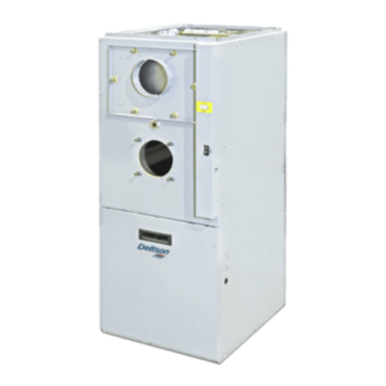
AMP SERIES
HIGH-BOY MULTIPOSITION
OIL-FIRED FURNACE
Models:
AMP112SD
AMP112SV
Attention:
Do not tamper with the unit or its controls.
Call a qualified service technician.
Manufactured by: Dettson Industries Inc.
for Innovair Solutions
Sherbrooke,
Qc,
www.dettson.com
2023-10
Canada
X40184 Rev.I
Advertisement
Table of Contents

Related Manuals for Dettson innovair AMP Series


Summary of Contents for Dettson innovair AMP Series
- Page 1 Do not tamper with the unit or its controls. KEEP THE DOCUMENT NEAR THE UNIT FOR FUTURE Call a qualified service technician. REFERENCE. HOMEOWNER: Manufactured by: Dettson Industries Inc. for Innovair Solutions PLEASE KEEP THIS MANUAL NEAR THE FURNACE FOR Sherbrooke, Canada FUTURE REFERENCE.
-
Page 2: Table Of Contents
3.3.7 Supply Air Temperature Rise Test ..3.3.8 Limit control check ....3.3.9 Restart after Burner Failure ... . 3.4 EMERGENCY HEATING MODE - VARIABLE SPEED MOTOR (ECM) . - Page 3 g) Ask the technician installing your furnace to show and explain to you the following items: SAFETY i. The main disconnect switch or circuit breaker; 1.1 SAFETY LABELING AND ii. The shutt off valve on the oil tank iii. The oil filter and how to change it (it must be changed WARNING SIGNS once a year);...
-
Page 4: Installation
Figure 1: Location and dimensions of ventilation air 2 INSTALLATION openings in a closet door This furnace is a true multi-position unit, in that it will function in an upflow, downflow or horizontal configuration to the left or the right. Only a few modifications are required during installation to change from one position to another. -
Page 5: Horizontal Installation
2.3 ELECTRICAL SYSTEM cover of the Beckett NX burner to protect it from vent. ONLY the Multipoise 098 Series in downflow position requires the protection plate CAUTION provided with the unit. The exterior of the unit must have an uninterrupted ground to Figure 3: Downflow Installation minimize the risk of bodily harm, if ever an electrical problem develops. -
Page 6: Installation Of The Burner
2.6 VENTING Figure 7: Thermostat wiring, heating and air conditioning/heat pump with ECM variable speed WARNING motor OISONOUS CARBON MONOXIDE GAS FIRE AND EXPLOSION HAZARD Read and follow all instructions in this section. Never install a hand operated damper in the vent pipe. However, any Underwriters Laboratories listed, electrically operated automatic type vent damper may be installed if desired. -
Page 7: Blocked Vent Shut-Off Device (Bvso) For Chimney Venting
2.7 BLOCKED VENT SHUT-OFF conditions will require that only outside air be used for combustion. The following areas or types of structures may contain or be exposed DEVICE (BVSO) FOR CHIMNEY to certain substances, potentially requiring outside air for combustion: 1. -
Page 8: Ducting
2.10 DUCTING Table 1: Blower speed adjustments, 4-speed motor WARNING HEATING OR A/C RECOMMENDED FURNACE OUTPUT BLOWER SPEED OISONOUS CARBON MONOXIDE GAS HAZARD APPLICATION DO NOT draw return air from inside a closet or utility room. 0.50 USGPH MED-LOW Return air MUST be sealed to the furnace casing. Failure to properly seal ducts can result in death, bodily injury HEATING 0.60 USGPH... -
Page 9: Air Conditioner (Or Heat Pump)
Table 2: Airflow adjustments heating mode Table 3: Airflow adjustments air conditioning mode SW1-HEAT INPUT SW2-COOL INPUT DIP Switch Positions USGPH DIP Switch Positions USGPH POSITION POSITION 0.63 0.80 0.68 0.80 *Alternate adjustments for both input rate (refer to air flow tables) Table 4: Airflow adjustments heating mode Table 5: Delay adjustments heating mode... -
Page 10: Checks And Adjustments
3.3.5 Overfire pressure test 5) When the call for heat is satisfied, the solenoid valve closes, the flame goes out and the burner motor stops (after post purge The overfire draft that is taken through the observation port, located delay, if applicable). above the burner, is a measurement necessary to determine if there 6) The blower stops shortly after the burner. -
Page 11: Emergency Heating Mode - Variable Speed Motor (Ecm)
3.4 EMERGENCY HEATING MODE 7. Before re-assembling the unit, the heat exchanger and combustion chamber should be inspected to determine if - VARIABLE SPEED MOTOR replacement is required; 8. After the cleaning, replace the heat exchanger baffles, flue collar (ECM) plate and oil burner;... -
Page 12: Furnace Information
5 FURNACE INFORMATION Model: ..........Serial number: . -
Page 13: Technical Specifications
6 TECHNICAL SPECIFICATIONS Table 6: Technical specifications 112 Series, multi-position models UNITS WITH 1/2 HP 4-SP. MOTOR UNITS WITH 1/2 HP ECM MOTOR RATING AND PERFORMANCE Firing rate(USGPH)* 0.68 0.80 0.68 0.80 Input (BTU/h)* 95,200 112,000 95,200 112,000 Heating temperature rise (Degr. F)* 55 - 75 Degr. -
Page 14: Table 7: Airflow Data, Models With 1/2Hp Ecm Motor
Table 7: Airflow data, models with 1/2HP ECM motor OIL HEATING MODE 24 VAC input (R) on W only SW1- HEAT HEAT INPUT CFM with SW3-ADJ CFM with SW3-ADJ CFM with SW3-ADJ DIP switch position A DIP switch position B DIP switch position C DIP switch position (USGPH) -
Page 15: Figure 9: Furnace Dimensions
Table 8: Airflow data model with 1/2 HP 4-speed motor (PSC) EXTERNAL STATIC PRESSURE WITH AIR FILTER BLOWER SPEED 0.2” (W.C.) 0.3” (W.C.) 0.4” (W.C.) 0.5” (W.C.) 0.6” (W.C.) 0.7” (W.C.) HIGH 1550 1510 1460 1400 1320 1220 MED-HIGH 1320 1280 1240 1200... -
Page 16: Figure 10: Wiring Diagram 4-Speed Motor (Psc)
Figure 10: Wiring diagram 4-speed motor (PSC) -
Page 17: Figure 11: Wiring Diagram Variable Speed Motor (Ecm)
Figure 11: Wiring diagram variable speed motor (ECM) -
Page 18: Figure 12: Parts List With 4-Speed Motor (Psc)
Figure 12: Parts list with 4-speed motor (PSC) -
Page 19: Table 10: Parts List With 4-Speed Motor Psc
Table 10: Parts list with 4-speed motor PSC Item Description Comments B03622 HEAT EXCHANGER Heat exchanger only J06L002 SEAL STRIP, DIA 1/8 x 25’ B03652-01 FRONT PANEL ASSEMBLY Panels, insulation and labels included B03667 FRONT PANEL INSULATION B03637-01 BAFFLE, LATERAL B03651-01 SIDE PANEL ASSEMBLY (RIGHT) Panels, insulation and baffle included... -
Page 20: Figure 13: Parts List With Variable Speed Motor (Ecm)
Figure 13: Parts list with variable speed motor (ECM) -
Page 21: Table 11: Parts List With Variable Speed Motor (Ecm)
Table 11: Parts list with variable speed motor (ECM) Item Description Comments B03622 HEAT EXCHANGER Heat exchanger only J06L002 SEAL STRIP, DIA 1/8 x 25’ B03652-01 FRONT PANEL ASSEMBLY Panels, insulation and labels included B03667 FRONT PANEL INSULATION B03637-01 BAFFLE, LATERAL B03651-01 SIDE PANEL ASSEMBLY (RIGHT) Panels, insulation and baffle included...
Need help?
Do you have a question about the innovair AMP Series and is the answer not in the manual?
Questions and answers