
Subscribe to Our Youtube Channel
Related Manuals for Mindray AS3000


Summary of Contents for Mindray AS3000
- Page 1 O p e r a t i n g i n s t r u c t i o n s Datascope ™ A n e s t h e s i A D e l i v e r y s y s t e m 0070-01-0684-02_revB_AS3000 ops color.indd 1 3/10/10 5:14:09 PM...
- Page 2 O p e r a t i n g i n s t r u c t i o n s Datascope ™ A n e s t h e s i A D e l i v e r y s y s t e m...
- Page 3 Spectrum OR is a U.S. trademark of Mindray DS USA, Inc. Copyright © Mindray DS USA, Inc., 2008. All rights reserved. Contents of this publication may not be reproduced in any form without permission of Mindray DS USA, Inc. AS3000™ Operating Instructions...
-
Page 4: Table Of Contents
PCV Parameter Settings ........................2 - 19 Synchronized Intermittent Mandatory Ventilation (SIMV) ................2 - 20 SIMV Parameter Settings ........................2 - 21 Pressure Support (PS) ..........................2 - 22 PS Parameter Settings ........................2 - 23 Parameter Monitoring............................2 - 24 Pressure..............................2 - 24 AS3000™ Operating Instructions 0070-10-0684-01... - Page 5 Electrical Power Requirements ........................5 - 4 Battery Power Requirements ........................5 - 4 Auxiliary Outlets............................5 - 4 Pneumatic ..............................5 - 4 Central Gas Supply Requirements......................5 - 4 Cylinder Gas Supply Requirements ......................5 - 4 Gas Management ............................5 - 4 0070-10-0684-01 AS3000™ Operating Instructions...
- Page 6 Warranty Statements ............................5 - 15 Disclaimers ..............................5 - 16 Product Improvements ..........................5 - 16 Phone Numbers and How To Get Assistance......................5 - 16 Manufacturer’s Responsibility ...........................5 - 16 Glossary........................... 6 - 1 Glossary of Terms ............................6 - 1 AS3000™ Operating Instructions 0070-10-0684-01...
- Page 7 Table of Contents This page intentionally left blank. 0070-10-0684-01 AS3000™ Operating Instructions...
-
Page 8: Foreword
Foreword The AS3000 Anesthesia Delivery System Operating Instructions are intended to provide information for proper operation. General knowledge and understanding of the features and functions of the AS3000 Anesthesia Delivery System are prerequisites for its proper use. NOTE: Do not operate this system before reading these instructions. -
Page 9: Warnings
WARNING: Electric shock and fire hazard: Do not clean the machine while it is on and/or plugged in. WARNING: Disconnect the power plug from the mains supply before removing the rear panels or servicing the AS3000 unit. 0070-10-0684-01 AS3000™ Operating Instructions... - Page 10 WARNING: The AS3000 should not be used adjacent to or stacked with other equipment. If adjacent or stacked use is necessary, the AS3000 should be observed to verify normal operation in the configuration in which it will be used.
- Page 11 Introduction Warnings WARNING: To avoid tip hazards, use care when moving the AS3000 up or down inclines, around corners and across thresholds. Remove all monitoring equipment mounted to the side of the AS3000 prior to transport. Do not attempt to roll the AS3000 over hoses, cords or other obstacles.
-
Page 12: Cautions
CAUTION: Use cleaning agent sparingly. Excess fluid could enter the machine, causing damage. CAUTION: Do not autoclave any parts of the AS3000 unless specifically identified as autoclaveable in this manual. Clean the AS3000 only as specified in this manual. CAUTION: Do not autoclave the airway pressure limiting (APL) valve. - Page 13 Verify that the bellows is fully inflated before starting an automatic ventilation mode on the patient. If the bellows is deflated and at the bottom of its travel at the start of an automatic ventilation mode, the bellows may become deformed. 0070-10-0684-01 AS3000™ Operating Instructions...
-
Page 14: Notes
Intended Use The AS3000 Anesthesia Delivery System is a device used to administer to a patient, continuously or intermittently, a general inhalation anesthetic, and to maintain a patient's ventilation. -
Page 15: Symbols
Protective Earth (Ground) Latex-free product Interference may occur in the Fuse vicinity of equipment marked with this symbol Catalog Number Plug Icon Serial Number Date Code Lock Recycle Separate treatment from general Unlock waste at end of life 0070-10-0684-01 AS3000™ Operating Instructions... -
Page 16: Product Description
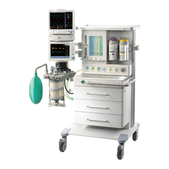
Product Description FIGURE 1-1 The AS3000 Anesthesia Delivery System AS3000™ Operating Instructions 0070-10-0684-01 1 - 1... -
Page 17: General System Overview
• An O flush button Safety systems within the AS3000 work to prevent hypoxic mixtures from being delivered to the patient. Nitrous oxide will not be delivered unless oxygen pressure is present. A mechanical safety system assures that at least 21% O... -
Page 18: Vaporizer Mounting
In the case of an AC power failure, the AS3000 will operate for a minimum of 45 minutes on battery power. A recessed main switch is provided to power the system ON and OFF. -
Page 19: Responsibilities Of Operators
Product Description Responsibilities of Operators The proper function of the AS3000 system can only be guaranteed if it is operated and serviced in accordance with the information provided in this manual and the AS3000 Service Manual. Non-compliance with this information voids all guarantee claims. -
Page 20: Key Features
Additional Rail mount extended work surface Electronic PEEP Positive End Expiratory Pressure (PEEP) is set and controlled electronically. Clear Data Display 2 large waveforms for pressure and volume or Spirometry Loops - standard AS3000™ Operating Instructions 0070-10-0684-01 1 - 5... -
Page 21: User Interface
The following figure is an example of the User Interface with the display during system power-up. Keypad Area ™ Display Navigator Knob FIGURE 1-2 Example of the User Interface with the display during system power-up 1 - 6 0070-10-0684-01 AS3000™ Operating Instructions... -
Page 22: Display
2.12.3.1 and 2.12.3.2 for table listings of the individual messages and their associated priority levels. High priority messages are red. Medium and low priority messages are yellow. Up to 2 messages can be displayed in this area. AS3000™ Operating Instructions 0070-10-0684-01 1 - 7... - Page 23 (See item 10 in this section for descriptions of the parameter setup tiles and how to adjust settings.) NOTE: A message will be displayed in the user message area to indicate that the displayed parameter values are for the pending ventilation mode. 1 - 8 0070-10-0684-01 AS3000™ Operating Instructions...
- Page 24 ™ setting adjustment. Rotating the Navigator Knob clockwise will increase the setting and rotating it counterclockwise will decrease the setting. The range of settings for each parameter has a maximum and minimum value. AS3000™ Operating Instructions 0070-10-0684-01 1 - 9...
- Page 25 1 bpm and its default is 4 bpm. • The range of settings for the Child patient type is 2 to 60 bpm, in increments of 1 bpm and its default is 4 bpm. 1 - 10 0070-10-0684-01 AS3000™ Operating Instructions...
- Page 26 • The range of settings for the Child patient type is 1 to 15 L/min, in increments of 1 L/min and its default is 2 L/min. NOTE: This parameter is available in the SIMV with PS and PS ventilation modes. AS3000™ Operating Instructions 0070-10-0684-01 1 - 11...
- Page 27 Adult and Child patient types is 0 to 2 seconds, in increments of 0.1 seconds. Its default is 0.5 seconds. NOTE: This parameter is available in the PCV, SIMV with PS, and PS ventilation modes. 1 - 12 0070-10-0684-01 AS3000™ Operating Instructions...
-
Page 28: Keypad Area
“Flow-Volume” loop display configuration. After both configurations have been cycled through the display, a third key press returns the display to the Pressure vs. Time and Flow vs. Time waveforms. AS3000™ Operating Instructions 0070-10-0684-01 1 - 13... - Page 29 If a change of setting (Ventilation Mode, Patient Type, Ventilation Parameter, Alarm Limit or System Setting) is in process, and any key except MUTE is pressed prior to confirming that change, the system will revert back to the previously confirmed setting. 1 - 14 0070-10-0684-01 AS3000™ Operating Instructions...
-
Page 30: Front View
Flush Button Provides high flow O to the inspiratory limb of the breathing system. This button is functional regardless of whether or not the system is powered ON. 8. AGSS Anesthetic Gas Scavenging System AS3000™ Operating Instructions 0070-10-0684-01 1 - 15... -
Page 31: Auxiliary Outputs/Fresh Gas Dosing Components
5. Oxygen Outlet High pressure O outlet for connecting external devices such as a jet ventilator. Use the tops of the floats when reading the flowmeter tubes. Turn knob counterclockwise to increase flow. 1 - 16 0070-10-0684-01 AS3000™ Operating Instructions... -
Page 32: Vaporizer Mounting Manifold
2. Valve Cartridge of Vaporizer index and outlet parts. Vaporizer Mount 3. Mounting Bar Bar holds two vaporizers. An interlock within the vaporizers provides for use of one vaporizer to deliver one agent at a time. AS3000™ Operating Instructions 0070-10-0684-01 1 - 17... -
Page 33: Breathing System
Breathing System Product Description Breathing System 1.8.1 Top View FIGURE 1-8 AS3000 Breathing System, Top View PART(S) DESCRIPTION 1. Breathing System Six pneumatic hoses that control the manual/vent switch Pneumatic Hoses and exhaust valves in the breathing system and provide the ventilator with flow sensor information. -
Page 34: Bottom View
The APL valve and PAW gauge numerics are for reference only. Calibrated patient airway pressure is displayed on the user interface. 1.8.2 Bottom View FIGURE 1-9 AS3000 Breathing System, Bottom View PART(S) DESCRIPTION 1. Drive Gas Hose Provides drive gas to the bellows. -
Page 35: Rear View
, Air, and N O from the central gas Supply Connections supply. 3. Cylinders Supply tanks containing high pressure O , Air, and O to act as a backup supply if the pipeline pressure is removed. 1 - 20 0070-10-0684-01 AS3000™ Operating Instructions... -
Page 36: Operations
However, all of these settings can be changed for specific patient or departmental needs. The AS3000 offers controlled ventilation for Adult and Child patient sizes, with default ventilation parameters and alarm related settings for each. -
Page 37: Initial Setup
17. Plug the mains cable into a grounded socket and switch on the power supply using the mains switch (located on the front of the machine). Wait until the ventilator display provides information about the leak test. 2 - 2 0070-10-0684-01 AS3000™ Operating Instructions... -
Page 38: Preoperative Checkout
4. Prepare the Anesthetic Gas Scavenging System (AGSS). Refer to section 3.1.11 for removal instructions: a. Remove the AGSS from the AS3000. While viewing the float, turn the AGSS upside down to verify whether the float moves freely along its shaft. Replace the float as necessary. - Page 39 O, and Air gas flows to mid-range. b. Ensure that the O gas cylinder is closed. c. Disconnect the O supply from the AS3000. d. Verify that all flows, except Air, fall to zero. 2 - 4 0070-10-0684-01 AS3000™ Operating Instructions...
- Page 40 O2 Supply Failure is displayed in red text i. Shut off all flow-control valves. j. Re-connect the O supply to the AS3000. 16. Perform High Pressure Leak Test: a. Connect a breathing circuit and ventilation bag. b. Set APL Valve to 70 cm H c.
- Page 41 FiO reading. c. Verify that: • an alarm tone sounds • the alarm message Low FiO2 is displayed in red text d. Set the Low FiO alarm limit back to 18. 2 - 6 0070-10-0684-01 AS3000™ Operating Instructions...
- Page 42 CO absorbent is replaced. 28. Test for leaks in the machine and vaporizers by performing the High Pressure Leak Test as described in step 16 of this section. AS3000™ Operating Instructions 0070-10-0684-01 2 - 7...
-
Page 43: Before Every Patient
To prevent the bellows from deflating completely to the bottom of its travel: • Do not disconnect the breathing circuit from the AS3000 or the patient while the ventilator is running in an automatic ventilation mode. Return to MANUAL or STANDBY modes first. -
Page 44: Initial Power-Up
Pressure vs. Time and Flow vs. Time waveforms in STANDBY ventilation mode. NOTE: If the Leak test result is greater than 1000 ml and the user selects MANUAL, Automatic Ventilation will be disabled. NOTE: Bypassing the Compliance test is not recommended. AS3000™ Operating Instructions 0070-10-0684-01 2 - 9... -
Page 45: Adjusting The Date And Time
12 Hour or 24 Hour. NOTE: The default format is 12 Hour and the adjustable parameters are hours and minutes. 3. Select Done to save the time adjustments and return to the System menu tab. 2 - 10 0070-10-0684-01 AS3000™ Operating Instructions... -
Page 46: Vaporizer Installation
Unlocked Position FIGURE 2-1 Vaporizer, Unlocked 2. Rotate the locking mechanism handle clockwise into the locked position as shown in FIGURE 2-2. Locking Mechanism Handle in the Locked Position FIGURE 2-2 Vaporizer, Locked AS3000™ Operating Instructions 0070-10-0684-01 2 - 11... -
Page 47: Oxygen Sensor Calibration
If the system is going to be used during the calibration, insert the O cell plug (item 6, FIGURE 1-8) into the port from which the oxygen sensor was removed using a push and turn motion. 2 - 12 0070-10-0684-01 AS3000™ Operating Instructions... - Page 48 FIGURE 2-4 Oxygen Sensor FIGURE 2-5 Oxygen Sensor Calibration Instructions Calibration Progress Bar FIGURE 2-6 Oxygen Sensor FIGURE 2-7 Oxygen Sensor Calibration Instructions (UI Calibration Progress Bar versions 2.24 and lower) (UI versions 2.24 and lower) AS3000™ Operating Instructions 0070-10-0684-01 2 - 13...
- Page 49 If the oxygen sensor must be replaced, select the Exit button, replace the oxygen sensor, and then repeat the calibration. FIGURE 2-8 Oxygen Sensor FIGURE 2-9 Oxygen Sensor Calibration Successful Calibration Failed 2 - 14 0070-10-0684-01 AS3000™ Operating Instructions...
-
Page 50: Ventilation Modes
Rotate the APL valve adjustment knob fully counterclockwise, until the SP marking on the knob lines up with the index mark on the bottom section of the valve (see item 11 in FIGURE 1-8). The valve will then be open for spontaneous patient breathing. AS3000™ Operating Instructions 0070-10-0684-01 2 - 15... -
Page 51: Continuous Mandatory Ventilation (Cmv)
Note that in certain cases, when the ventilator is operating near its performance limits, compliance compensation will not be possible. When the AS3000’s performance limit is reached, it will not be possible to increment the frequency setting or the tidal volume setting and the message Ventilator setting is not possible. -
Page 52: Cmv Parameter Settings
O (± 2 cmH 13 - 17 cmH O (± 3 cmH 18 - 24 cmH O (± 6 cmH 25 - 30 cmH O (± 12 cmH Defaults appear in parenthesis in bold text. AS3000™ Operating Instructions 0070-10-0684-01 2 - 17... -
Page 53: Pressure Controlled Ventilation (Pcv)
SLOPE from the set I:E ratio and frequency. In case of conflict, the set I:E ratio and frequency will override the set T time. SLOPE 2 - 18 0070-10-0684-01 AS3000™ Operating Instructions... -
Page 54: Pcv Parameter Settings
O (± 2 cmH 13 - 17 cmH O (± 3 cmH 18 - 24 cmH O (± 6 cmH 25 - 30 cmH O (± 12 cmH Defaults appear in parenthesis in bold text. AS3000™ Operating Instructions 0070-10-0684-01 2 - 19... -
Page 55: Synchronized Intermittent Mandatory Ventilation (Simv)
Pressure Supported (PS) spontaneous breathing between needed mandatory breaths. SIMV in the AS3000 is a volume mode where the user can set the tidal volume, frequency, inspiratory pause, PEEP, and inspiratory time. Mandatory breaths are synchronized with the patient’s inspiratory effort. -
Page 56: Simv Parameter Settings
O (± 2 cmH 13 - 17 cmH O (± 3 cmH 18 - 24 cmH O (± 6 cmH 25 - 30 cmH O (± 12 cmH Defaults appear in parenthesis in bold text. AS3000™ Operating Instructions 0070-10-0684-01 2 - 21... -
Page 57: Pressure Support (Ps)
2.10.6 Pressure Support (PS) In Pressure Support (PS) mode, the patient’s effort is supported by the AS3000 at a preset level of inspiratory pressure. Inspiration is triggered and cycled by patient effort. The user can set the Trigger flow, Pressure Support level, PEEP, minimum allowed breathing frequency, and Slope Time. -
Page 58: Ps Parameter Settings
O (± 2 cmH 13 - 17 cmH O (± 3 cmH 18 - 24 cmH O (± 6 cmH 25 - 30 cmH O (± 12 cmH Defaults appear in parenthesis in bold text. AS3000™ Operating Instructions 0070-10-0684-01 2 - 23... -
Page 59: Parameter Monitoring
Pressure (MEAN) is configured from the System menu tab. The associated Pressure vs. Time and Flow vs. Time waveforms are displayed together in the Waveform Area. FIGURE 2-14 Example Pressure vs. Time and Flow vs. Time Waveforms 2 - 24 0070-10-0684-01 AS3000™ Operating Instructions... -
Page 60: Volume
) is displayed. If data is under range, a down- arrow ( ) is displayed. NOTE: The high alarm limit is displayed to the top right of the reading. The low alarm limit is displayed to the bottom right of the reading. AS3000™ Operating Instructions 0070-10-0684-01 2 - 25... -
Page 61: Spirometry
Knob will then save the currently plotting loop as a reference loop (in a different color). NOTE: Only one reference loop can be saved. Pressure-Volume Spirometry Loop FIGURE 2-15 is an example of the Pressure-Volume loop. FIGURE 2-15 Example Pressure-Volume Loop 2 - 26 0070-10-0684-01 AS3000™ Operating Instructions... - Page 62 L/min and its scale is -90 to +90, in increments of 45, but only absolute numbers are displayed. The X-axis represents Volume. The unit of measure is ml and its scale is 0 to 1400, in increments of 750. AS3000™ Operating Instructions 0070-10-0684-01 2 - 27...
-
Page 63: Alarms
Child: 18 Child: 100 The increment for all ranges and all units of measure is 1. Available in all ventilation modes except STANDBY. ™ 2. To save alarm limit settings, press the Navigator Knob. 2 - 28 0070-10-0684-01 AS3000™ Operating Instructions... -
Page 64: Alarm Volume
Based on the priority levels listed in the tables in sections 2.12.3.1 and 2.12.3.2, each message will display in the Alarm Message Area (item 2, FIGURE 1-3) with an associated symbol as follows: • Low priority • Medium priority • High priority AS3000™ Operating Instructions 0070-10-0684-01 2 - 29... -
Page 65: Technical Messages
Contact technical support. Expiration Sensor Failure The expiration sensor This alarm occurs during data is incorrect. startup only and renders the system non- operational. Contact technical support. 2 - 30 0070-10-0684-01 AS3000™ Operating Instructions... - Page 66 This alarm occurs during testing, no response startup only and places was received from the system in STANDBY the alarm speaker. ventilation mode. All system functions except audible alarms are available. Contact technical support. AS3000™ Operating Instructions 0070-10-0684-01 2 - 31...
- Page 67 Applicable to UI versions to Shut Down Completely the unit too quickly. 2.25 and higher. This alarm occurs during startup only. Shut down the unit and wait until the backlight is fully extinguished before restoring power. 2 - 32 0070-10-0684-01 AS3000™ Operating Instructions...
-
Page 68: Functional Alarm Messages
These functional alarm messages are disabled when Manual Mode Alarm control on the Main Screen is set to “OFF” and the ventilation mode is set to MANUAL. AS3000™ Operating Instructions 0070-10-0684-01 2 - 33... -
Page 69: Alarm Functions Test
1. Activate the CMV ventilation mode. 2. Set attributes as follows: ATTRIBUTE SETTING Patient Size Adult Breath Rate PEEP Flow 2 Liters/minute 3. Perform steps 20 to 23 of the Preoperative Checkout in section 2.4. 2 - 34 0070-10-0684-01 AS3000™ Operating Instructions... -
Page 70: System
Provides selections of Pplat (Plateau Pressure) or Pmean pressure display. The default is Pplat. 2. Language Allows the user to choose from available display languages. NOTE: The AS3000 is only available in English. 3. Display Accesses the AS3000’s demo mode. NOTE: This Feature is password protected and is intended for use by Mindray personnel only. - Page 71 Test Time the time the test was performed. If the Leak Test was bypassed, a value of Bypassed will be displayed for Leak Value (see figure 2-20). FIGURE 2-20 Example of a Bypassed Leak Test 2 - 36 0070-10-0684-01 AS3000™ Operating Instructions...
-
Page 72: User Maintenance
Never immerse the oxygen sensor or its connector in any type of liquid. • Dispose of the oxygen sensor per the manufacturer’s specification. CAUTION: Do not wash the inner surface of the oxygen sensor. AS3000™ Operating Instructions 0070-10-0684-01 3 - 1... - Page 73 Leak Test and the Compliance Test. CAUTION: The PAW gauge and oxygen sensor cannot withstand immersion or the heat and pressure of autoclaving. CAUTION: Do not autoclave the airway pressure limiting (APL) valve. 3 - 2 0070-10-0684-01 AS3000™ Operating Instructions...
-
Page 74: Cleaning And Disinfection
If using disinfectant wipes, follow the manufacturer’s instructions for use. 3.1.3 Bellows Assembly FIGURE 3-1 Bellows Assembly Read all content in this section before disassembling, cleaning, disinfecting, and re- assembling the bellows to avoid equipment malfunction and patient injury. AS3000™ Operating Instructions 0070-10-0684-01 3 - 3... - Page 75 Remove the bellows dome by turning it counterclockwise and lifting it away from the breathing system. See FIGURE 3-2. FIGURE 3-2 Removing the Bellows Dome 2. Detach the bellows from the base plate as shown in FIGURE 3-3. FIGURE 3-3 Detaching the Bellows 3 - 4 0070-10-0684-01 AS3000™ Operating Instructions...
- Page 76 4. Remove the bellows adapter ring from inside the bellows as shown in FIGURE 3-5. FIGURE 3-5 Removing the Bellows Adapter Ring AS3000™ Operating Instructions 0070-10-0684-01 3 - 5...
- Page 77 After all bellows components are completely dry, inspect them for damage before disinfection or re-assembly and functional testing. d. If disinfecting the bellows components, continue with step 7, otherwise skip to step 8. 3 - 6 0070-10-0684-01 AS3000™ Operating Instructions...
-
Page 78: Inspiration And Expiration Valves
The following procedure is written generically for a single, unspecified valve. It should be performed on both the inspiration and expiration valves. Control Hose Tall Bag Expiration Inspiration Valve Valve FIGURE 3-7 Location of Expiration and Inspiration Valves AS3000™ Operating Instructions 0070-10-0684-01 3 - 7... - Page 79 Valve Dome Valve O-ring FIGURE 3-9 Valve Dome Removal CAUTION: The valve disc is fragile and must, therefore, be handled with care while removing the valve cage from the valve assembly. 3 - 8 0070-10-0684-01 AS3000™ Operating Instructions...
- Page 80 The valve disc is fragile and must, therefore, be handled with care while removing it from the valve cage. 4. Remove the valve disc from the valve cage as shown in FIGURE 3-11. Valve Disc FIGURE 3-11 Valve Disc Removal AS3000™ Operating Instructions 0070-10-0684-01 3 - 9...
- Page 81 7. Reassemble the valve components in the reverse order, noting any previously stated CAUTION. Prior to use after cleaning or disinfecting, power up the system as described in section 2.6 and follow the on-screen prompts to perform the Leak Test and the Compliance Test. 3 - 10 0070-10-0684-01 AS3000™ Operating Instructions...
-
Page 82: Oxygen Sensor
2. Clean the oxygen sensor exterior with a soft, lint-free cloth, and a mild detergent and water solution. Allow to dry thoroughly. 3. Inspect the oxygen sensor for damage and replace as necessary. 4. Re-insert the oxygen sensor if it had been removed. AS3000™ Operating Instructions 0070-10-0684-01 3 - 11... -
Page 83: Apl Valve
4. Replace the APL valve by turning its base clockwise until it is securely tightened. Prior to use after cleaning or disinfecting, power up the system as described in section 2.6 and follow the on-screen prompts to perform the Leak Test and the Compliance Test. 3 - 12 0070-10-0684-01 AS3000™ Operating Instructions... -
Page 84: Paw Gauge
3. Re-insert the PAW gauge if it was removed. Prior to use after cleaning or disinfecting, power up the system as described in section 2.6 and follow the on-screen prompts to perform the Leak Test and the Compliance Test. AS3000™ Operating Instructions 0070-10-0684-01 3 - 13... -
Page 85: Bag Arm
4. Reassemble the bag arm to the breathing system. Prior to use after cleaning or disinfecting, power up the system as described in section 2.6 and follow the on-screen prompts to perform the Leak Test and the Compliance Test. 3 - 14 0070-10-0684-01 AS3000™ Operating Instructions... -
Page 86: Absorber Canisters
Open position and collect any water that may have gathered. Turn the valve to the Close position and discard the water. Drain Valve Absorber Drain FIGURE 3-18 Absorber Drain Valve (Close Up View) AS3000™ Operating Instructions 0070-10-0684-01 3 - 15... - Page 87 Absorber Canisters while adhering to facility policies and procedures. WARNING: Use extreme care while handling the absorbent as it is a caustic irritant. NOTE: Ensure that the absorber canisters are completely dry before adding absorbent. 3 - 16 0070-10-0684-01 AS3000™ Operating Instructions...
-
Page 88: Breathing System Block
WARNING: Use care in lifting and manipulating the breathing system block during removal from its mounting arm as handling may be awkward due to its weight and shape. AS3000™ Operating Instructions 0070-10-0684-01 3 - 17... - Page 89 8. Reassemble the breathing system components in reverse order. Prior to use after cleaning or disinfecting, power up the system as described in section 2.6 and follow the on-screen prompts to perform the Leak Test and the Compliance Test. 3 - 18 0070-10-0684-01 AS3000™ Operating Instructions...
-
Page 90: Agss (Anesthetic Gas Scavenging System) And Agss Transfer Hose
AGSS (Anesthetic Gas Scavenging System) and AGSS Transfer Hose 1. Disconnect the EVAC hose from the AGSS. 2. Remove the AGSS and Transfer Hose from the AS3000 as shown in FIGURE 3-22. FIGURE 3-22 AGSS and Transfer Hose Removal AS3000™ Operating Instructions... - Page 91 FIGURE 3-23 Removal of AGSS Top FIGURE 3-24 AGSS Filter Inspection 5. Reassemble the AGSS and Transfer Hose and reconnect them to the AS3000 in the reverse order. 3 - 20 0070-10-0684-01 AS3000™...
-
Page 92: Regular Maintenance
2. Perform an overall visual inspection of the system. 3. Power up the system as described in section 2.6 and follow the on-screen prompts to perform the Leak Test and the Compliance Test. AS3000™ Operating Instructions 0070-10-0684-01 3 - 21... - Page 93 Regular Maintenance User Maintenance This page intentionally left blank. 3 - 22 0070-10-0684-01 AS3000™ Operating Instructions...
-
Page 94: Accessories
Accessories The following accessories are designed for the AS3000 Anesthesia Delivery System. The use of other accessories is not recommended. To place an order for these or other accessories, contact Customer Service at 1.800.288.2121 or order accessories online at www.mindray.com. -
Page 95: Co 2 Absorbers
Absorber Pre-Pack (P/N 0683-00-0326-01) • Loose Fill CO Absorber (P/N 0683-00-0325-01) Miscellaneous • DPM 6/7 to AS3000 Installation Kit (P/N 0040-00-0452) • DPM 6/7 Module Rack Mounting Kit (P/N 0040-00-0451) • Monitor Mounting Arm, Pivoting, 16” (P/N 0436-00-0198) • Suction Regulator (P/N 0992-00-0256) •... -
Page 96: Product Specifications
Between Equipment and Patient: the patient. Degree of Mobility: Mobile WARNING: Possible explosion hazard. Do not operate machine near flammable anesthetic agents or other flammable substances. Do not use flammable anesthetic agents (i.e., ether or cyclopropane.) AS3000™ Operating Instructions 0070-10-0684-01 5 - 1... -
Page 97: Astm F 1208 - 89 (2005) Disclosures
Anesthesia Breathing Systems. 5.2.1 Leakage of Breathing System The AS3000 complies with ASTM F 1208 – 89 (2005) section 7.1.1 — The maximum leakage of the breathing system does not exceed 300 mL/min when pressurized to 3.0 kPa (30 cmH 5.2.2... -
Page 98: General
WARNING: Due to the size and weight of the A3000, it should only be moved by qualified personnel. WARNING: To avoid tip hazards, use care when moving the AS3000 up or down inclines, around corners and across thresholds. Remove all monitoring equipment mounted to the side of the AS3000 prior to transport. -
Page 99: Electrical
Mains power supply: 100 to 240 VAC, 50/60 Hz, 10 A Current input: 120 VAC - 10 A (2 A for AS3000, 8 A for auxiliary outlets) Power consumption: Less than 200 VA (not including auxiliary outlets) Main Fuse: 2 x 10A 5.5.2... -
Page 100: Breathing System
(not available in SIMV or PS modes) Inverse I:E ratio: 1.5:1, 2:1, 2.5:1, 3:1, 3.5:1, 4:1 (not available in SIMV or PS modes) Plateau (End Insp.): Off, 5% - 60% of inspiratory period (CMV and SIMV modes only) AS3000™ Operating Instructions 0070-10-0684-01 5 - 5... - Page 101 0 - 100 vol% O resolution 1%, response time (80%) less than 10 sec. Pressure monitor: Real-time graphics (waveform) Numerical pressure values for PEEP, Pmean, Ppeak, Pplateau Pressure range: –20 to 99 cmH 5 - 6 0070-10-0684-01 AS3000™ Operating Instructions...
-
Page 102: Accuracy Of The Measurements After 5 Breaths
Rate: ± 1 bpm* ATPS (Ambient Temperature Pressure Saturated) 5.10 Anesthetic Gas Scavenging System (Low Flow) Flow Range: 25 to 50 l/min Maximum constant flow before 50 l/min spillage occurs: Particle Filter: Replaceable AS3000™ Operating Instructions 0070-10-0684-01 5 - 7... -
Page 103: Inputs / Outputs
Breathing System Heater Four-pin connector for Breathing System Heater cable. 5.11.1.5 External Communication Port Port B is available for RS-232 digital communication per Communication Protocol Document (P/N 0070-00-0706). Contact Mindray for more information. 5.11.2 Pneumatic 5.11.2.1 Pipeline connections DISS threaded body as per CGA V-5 for all three gases (O O, Air) 5.11.2.2... -
Page 104: Oxygen Gas Power Outlet
Knob - located in the Keypad Area for control of the user interface 5.12.1.2 Main Switch ON/OFF switch for power to the AS3000 system. 5.12.1.3 Vaporizer/Work Light A three-position switch (OFF, LOW, and HIGH) that controls the lighting over the work surface and vaporizers. -
Page 105: Cylinder Pressure Gauges
The button returns to its original closed position when released. 5.12.2.5 APL Valve The APL valve for limiting maximum breathing pressure in manual mode is located on the Breathing System block. 5 - 10 0070-10-0684-01 AS3000™ Operating Instructions... -
Page 106: Electromagnetic Capability
TABLE 5-1 GUIDANCE AND DECLARATION - ELECTROMAGNETIC EMISSION The AS3000 is intended for use in the electromagnetic environment specified below. The customer or the user of the AS3000 should assure that it is used in such an environment. EMISSIONS TEST... - Page 107 TABLE 5-2 (Continued) GUIDANCE AND DECLARATION - ELECTROMAGNETIC IMMUNITY The AS3000 is intended for use in the electromagnetic environment specified below. The customer or the user of the AS3000 should assure that it is used in such an environment. IMMUNITY...
- Page 108 If the measured field strength in the location in which the AS3000 is used exceeds the applicable RF compliance level above, the AS3000 should be observed to verify normal operation. If abnormal performance is observed, additional measures may be necessary, such as reorienting or relocating the AS3000.
- Page 109 RECOMMENDED SEPARATION DISTANCES BETWEEN PORTABLE AND MOBILE RF COMMUNICATIONS EQUIPMENT AND THE AS3000 The AS3000 is intended for use in an electromagnetic environment in which radiated RF disturbances are controlled. The customer or the user of the AS3000 can help prevent...
-
Page 110: Warranty Statements
Mindray DS USA, Inc.’s option at the factory or at an authorized distributor, any product which shall under normal use and service appear to the Company to have been defective in material or workmanship. -
Page 111: Disclaimers
5.15.1 Product Improvements Mindray DS USA, Inc. retains the right to modify the machine and/or operating instructions without prior notification. These operating instructions explain all features of the AS3000 system and are correct at time of manufacture. Instructions and models produced at a later stage, may contain improvements or modifications that were not included in previous models. -
Page 112: Glossary
L/min liters per minute milliliter Minute Volume Not Applicable Paw or PAW Airway Pressure Pressure Controlled Ventilation PEEP Positive End-Expiratory Pressure Peak Inspiratory Pressure Pressure Support Ventilation Target Pressure TARGET ΔP Differential Pressure AS3000™ Operating Instructions 0070-10-0684-01 6 - 1... - Page 113 Glossary of Terms Glossary SIMV Synchronized Intermittent Mandatory Ventilation Inspiratory Time INSP Inspiratory Pause Time Inspiratory Slope Time SLOPE Trigger Flow Trigger Oxygen Consumption Index Tidal Volume Watch Dog Timer 6 - 2 0070-10-0684-01 AS3000™ Operating Instructions...
- Page 114 Glossary Glossary of Terms This page intentionally left blank. AS3000™ Operating Instructions 0070-10-0684-01 6 - 3...
- Page 115 0070-10-0684-01 Rev H October 07, 2010...
- Page 116 Tel: +31 33 25 44 911 • Fax: +31 33 25 37 621 Mindray (UK) Limited • 3 Percy Road • St. John’s Park • Huntingdon • Cambridgeshire PE29 6SZ • United Kingdom • Tel: 01480 416840 • Fax: 01480 436588 Mindray Medical France SARL •...
Need help?
Do you have a question about the AS3000 and is the answer not in the manual?
Questions and answers