Table of Contents
Advertisement
Quick Links
Advertisement
Table of Contents

Related Manuals for Mindray Resona I9


Summary of Contents for Mindray Resona I9
- Page 1 Resona I9/Resona I9 Exp/Resona I9S/Resona I9T/Resona I9 Easi/Resona I9 Nasa/Resona IV/Imagyn I9/Imagyn I9S/Imagyn I9 Easi/Nuewa I9/Nuewa I9S/Nuewa I9 Easi/Anesus I9/Anesus I9 Easi/Eagus I9/Nuewa I9T/Nuewa I9 Exp Diagnostic Ultrasound System Operator’s Manual [Basic Volume]...
-
Page 3: Table Of Contents
Contents Intellectual Property Statement ......................I Responsibility on the Manufacturer Party................... I Warranty ............................II Important Information ........................III About This Manual ..........................III Notation Conventions ........................III Operator’s Manuals .......................... IV Hardcopy Manuals ..........................IV Software Interfaces in this Manual ....................IV Conventions ............................ - Page 4 B-mode Image Optimizing ....................5-4 M Mode Image Optimization ....................5-11 Color Mode Image Optimization ..................5-13 Power Mode Image Optimization ..................5-18 V Flow ..........................5-20 PW/CW Mode Optimization ....................5-23 Color M Mode (CM) ......................5-29 Free Xros M Mode ......................5-30 5.10 TDI ............................
- Page 5 10.6 Print ..........................10-15 10.7 Back up Files using the DVD Drive .................. 10-16 10.8 Patient Task Management ....................10-16 10.9 Administration ........................10-17 10.10 Q-Path ..........................10-25 10.11 V-Access ........................... 10-26 11 DICOM/HL7......................... 11-1 11.1 DICOM Preset ........................11-1 11.2 DICOM Verifying .......................
- Page 6 17.4 Inspection of Peripherals and Optional Functions .............. 17-8 17.5 Checking Mechanical Safety ....................17-8 Appendix A Barcode Reader ..................A-1 Appendix B iWorks (Auto Workflow Protocol)............B-1 Appendix C Wireless LAN ..................C-1 Appendix D Ultrasound Gel Heater ................D-1 Appendix E Electrical Safety Inspection ..............
-
Page 7: Intellectual Property Statement
Contents of this manual are subject to change without prior notice. All information contained in this manual is believed to be correct. Mindray shall not be liable for errors contained herein or for incidental or consequential damages in connection with the furnishing, performance, or use of this manual. -
Page 8: Warranty
Mindray or repairs by people other than Mindray authorized personnel. -
Page 9: Important Information
7. Important data must be backed up on external memory media. 8. Mindray shall not be liable for loss of data stored in the memory of this system caused by operator error or accidents. 9. This manual contains warnings regarding foreseeable potential dangers, but you shall also be continuously alert to dangers other than those indicated. -
Page 10: Operator's Manuals
The diagnostic ultrasound system is not intended for CAUTION: ophthalmic use. Its use in this clinical specialty is contraindicated. U.S.A. Federal Law restricts this device to sale by or on the order of a physician. Operator’s Manuals You may receive multi-language manuals on compact disc or paper. Please refer to the English manual for the latest information and registration information. -
Page 11: Conventions
[Items in menu][Items in submenu]: select a submenu item following the path. Notification of Adverse Events As a health care provider, you may report the occurrence of certain events to SHENZHEN MINDRAY BIO-MEDICAL ELECTRONICS CO., LTD., and possibly to the competent authority of the Member state in which the user and / or patient is established. - Page 12 B-Hist B-Hist B-Hist B-Hist Color Double Model Profile Cross (Ellipse) (Trace) (Spline) (Rectangle) dist √ √ √ √ √ Nuewa I9 Exp × × × √ √ √ √ √ √ Anesus I9 × × √ √ √ √ Anesus I9 Easi ×...
-
Page 13: Safety Precautions
Safety Precautions 1.1 Safety Classification According to the type of protection against electric shock: CLASS I EQUIPMENT + INTERNALLY POWERED EQUIPMENT According to the degree of protection against electric shock: TYPE-BF APPLIED PART According to the degree of protection against harmful ingress of water or particulate matter: The main unit is classified as IPX0 The probe is classified as IPX7 The 2-pedal or 3-pedal footswitch (can be used in the operating room) is classified as IP68... -
Page 14: Meaning Of Signal Words
1.2 Meaning of Signal Words DANGER WARNING CAUTION In this manual, the signal words , NOTE and Tip are used regarding safety and other important instructions. The signal words and their meanings are defined as follows. Please understand their meanings clearly before reading this manual. Signal word Meaning Indicates an imminently hazardous situation that, if not avoided, will result in... -
Page 15: Safety Precautions
When using peripherals not powered by the auxiliary output of the ultrasound system, or using peripherals other than permitted by Mindray, make sure the overall leakage current of peripherals and the ultrasound system meets the requirement of the local medical device electrical regulation (like enclosure leakage current should be no more than 500uA of IEC60601-1), and the responsibility is held by the user. - Page 16 11. Do not use an aftermarket probe other than those specified by Mindray. The probes may damage the system causing a profound failure, e.g. a fire in the worst case. 12. Do not subject the transducers to knocks or drops. Use of a defective transducer may cause an electric shock.
- Page 17 You cannot repair the system under this circumstance and must call the Mindray Customer Service Department or sales representative. There is no risk of high-temperature burns during normal ultrasound examinations.
- Page 18 If the system is powered off improperly during operation, it may result in data damage of the system’s hard disk or system failure. Do not use a USB memory device (e.g., a USB flash drive, removable hard disk) which has unsafe data. Otherwise, system damage may result. It is recommended to only use the video devices specified in this manual.
- Page 19 To ensure optimal system operations, it is recommended that you maintain the system under a Mindray service agreement. 13. The replaceable fuse is inside the chassis. Refer replacing job to Mindray service engineers or engineers authorized by Mindray only.
- Page 20 8. Please use the disinfection or sterilization solution recommended in this operator’s manual; otherwise Mindray will not be liable for damage caused by other solutions. If you have any questions, please contact Mindray Customer Service Department or sales representative.
-
Page 21: Latex Alert
Latex Alert When choosing a probe sheath, it is recommended that you directly contact CIVCO for obtaining information regarding probe sheaths, pricing, samples and local distribution. For CIVCO information, please contact the following: CIVCO Medical Instruments Tel: 1-800-445-6741 www.civco.com Allergic reactions in patients sensitive to latex (natural rubber) may WARNING: range from mild skin reactions (irritation) to fatal anaphylactic shock, and may include difficulty breathing (wheezing), dizziness, shock,... -
Page 23: System Overview
System Overview Intended Use Resona I9 series Diagnostic Ultrasound System is applicable for adults, pregnant women, pediatric patients and neonates. It is intended for use in fetal, abdominal, pediatric, small organ (breast, thyroid, testes), neonatal and adult cephalic, trans-rectal, trans-vaginal, musculo-skeletal (conventional, superficial), adult and pediatric cardiac, trans-esoph. -
Page 24: System Configuration
2.3.2 Environmental Conditions Operational Conditions Storage and Transportation Conditions Ambient 0°C-40°C -20°C-55°C temperature Relative 20%-85% (no condensation) 20%-95% (no condensation) humidity Atmospheric 700 hPa-1060 hPa 700 hPa-1060 hPa pressure Do not use this system in the conditions other than those specified. WARNING: 2.3.3 External Dimensions and Weight... - Page 25 2.4.3 Options Item Remarks Pencil probe cable CW Module 4D module Built-in wireless adapter Battery assembly Should be configured with the bracket of the Ultrasound gel warmer ultrasound gel warmer. Should be configured with the ultrasound gel Ultrasound gel warmer holder warmer.
- Page 26 Item Remarks Wipes box bracket iScape View Free Xros M Free Xros CM Tissue Doppler Imaging Cardiology Package should be configured. Tissue Doppler Imaging should be TDI QA configured. Contrast Imaging Contrast Imaging should be configured. Contrast Imaging QA Cardiology Package should be configured. 4D module should be configured.
- Page 27 Item Remarks Smart Face 4D module and Obstetrics Package should be configured. Smart ICV Smart Planes CNS should be configured. Smart Scene 3D 4D module should be configured. Ultrasound Fusion Imaging Fusion imaging module or Fusion imaging module (including trolley) should be configured.
- Page 28 Item Remarks Cardiology Package Small Parts Package Urology Package Vascular Package Pediatrics Package Nerve Package Emergency&Critical Package Pelvic Floor Package Gynecology Package should be configured. Smart Pelvic Pelvic Floor Package should be configured. Gynecology Package should be configured. Vascular Package should be configured. RIMT Vascular Package should be configured.
- Page 29 2.4.4 Peripherals Supported Type Model HP OFFICEJET PRO 8100 (the printer driver requires manual Graph/text printer installation.) Black/white video printer MITSUBISHI P95DW-N (digital) Black/white video printer SONY UP-X898MD (analog) Digital color video printer SONY UP-D25MD Barcode reader LS2208, DS4308 FS-81-SP-2 (1-pedal) Footswitch 971-SWNOM (2-pedal) 971-SWNOM (3-pedal)
-
Page 30: Introduction Of Each Unit
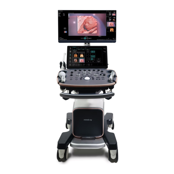
Introduction of Each Unit 2-8 System Overview... - Page 31 Name Function Monitor Displays the images and parameters during scanning. Touch Screen Screen-touching operator-system interface or control. Ultrasound gel warmer Used for heating the ultrasound gel. Transducer& Used for placing transducers or ultrasound gel temporarily. ultrasound gel holder Control panel Key- pressing operator-system interface or control.
- Page 32 Name Function Holding the right part of the handle to display the battery indicator on the control panel. Touch control handle NOTE: Available only after the battery assembly is configured. Control panel adjusting Used for lifting or swiveling the control panel. lever Used for locking the 3 full-lock casters.
-
Page 33: Back I/O Panel
Name Function Storage bin Used for temporal storage Supports the LCD display and adjusts the position and angle Monitor support arm of the LCD display. Rear handle Used for pushing and moving the system. Cooling vent Used for cooling the main unit. Back I/O panel Interface panel used for inputting and outputting signals. -
Page 34: Power Supply Panel
Symbol Function <4> S-Video S-Video signal output <5> HDMI High definition multimedia interface <6> Network port <7> 12 V indicator <8> 24 V indicator <9> 5V_STB indicator <10> DBG_FLAG indicator NOTE: S-VIDEO port performs better in analog video print. Power Supply Panel Name Function Alternative current... -
Page 35: Front I/O Panel
2.8 Front I/O Panel Name Function <1> Used for connecting a pencil probe. <2> PCG signal input port ECG lead signal input port/external ECG signal <3> input terminal <4> High speed USB port <5> High speed USB port <6> Audio input and output System Overview 2-13... -
Page 36: Control Panel
Control Panel Name Description Power button Turn on/turn off the system. AC (Alternating current). It turns on at AC supply. <1> Standby. It blinks in orange in standby status. Hard disk indicator. It blinks when reading the disk. Press the button to switch from A.Power and Volume. <2>... - Page 37 Name Description Press to enter or exit Color mode <6> Rotate to adjust Color/Power gain; while in 3D/4D mode, rotate the knob to make the 3D image rotates around Z axis. Press to enter or exit the M mode. When the M mode is enabled: If the Mark is not displayed, then press to display the Mark line;...
- Page 38 Name Description E-ink Supported. Set by the user in the Preset. Supports 3 kinds of save mode: 1. Save single-frame image. <19> Save 2. Save multi-frame image; 3. Select save mode based on different situations: Real time: Auto cine replay: save multi-frame image Freeze: save single-frame image.
- Page 39 Keyboard Common functional keys Function Confirm the input data; or moves the cursor to the head of next Enter row of the text or the input field. Cancel the operation or exit. Jump to the next operable item. Space key Insert a space.
-
Page 40: Symbols
Functions of key combination The system supports multi-language input; you can use the key combinations. The key combinations include [Shift], [Alt Gr], [Ctrl] and some alphabet keys. <Shift> key <Shift> + key: input the upper left letter of the key. For the alphabet keys (<A>~<Z>), press <Shift>+key to input the letter of different case with the current state. - Page 41 Symbol Description High speed USB port VGA input Reserved, used for separate video output S-VIDEO Audio input and output AUDIO HDMI High definition multimedia interface Microphone input jack When the probe locking lever points to , you can remove the probe. When the probe locking level points to , it means that the probe is locked and you can not remove the probe.
- Page 42 Symbol Description Caution: Federal Law restricts this device to sale by or on the order of a physician. MR Unsafe – the system is not intended to be used within magnetic resonance (MR) environment. 2-20 System Overview...
-
Page 43: System Preparation
When using peripherals not powered by the auxiliary output of the ultrasound system, or using peripherals other than permitted by Mindray, make sure the overall leakage current of peripherals and the ultrasound system meets the requirement of the local medical... -
Page 44: Connecting Power Cord & Protective Grounding
Maintain a generous – free air flowing space around the back and both sides of the system; failure may result due to increased rise in system CAUTION: operating temperature. Pay extra attention when moving the system on a sloping ground, do not move it on a more than 5°-sloped plane to avoid system toppling. - Page 45 CAUTION: immediately stop scanning. If the system continues to function improperly – fully shut down the system and contact Mindray Customer Service Department or sales representative. If you use the system in a persistent improperly functioning state – you may harm the patient or damage the equipment.
- Page 46 WARNING: The system is defective if any malfunctioning happens. In this case, shut down the system immediately and contact Mindray Customer Service Department or sales representative. NOTE: If there is over loading to the system, the breaker will switch into OFF to discontinue the power supply.
-
Page 47: Monitor Adjustment
To shut down the system in a direct way if you cannot do it normally: Directly turn off the circuit breaker or unplug the power cord. NOTE: DO NOT rush shutdown of the system or switch off the breaker in a direct way. It may make the data corrupted. - Page 48 Height and displacement adjustment Move the monitor support arm up or down to adjust the height, back and forth to adjust the displacement. NOTE: Take care not to trap your hands when adjusting the monitor up and down. Rotate the monitor The monitor can be rotated 90°...
- Page 49 Lock the monitor If the ultrasound system is required to be moved within a short distance (for example: move to other department), turn the monitor to the horizontal level, push it to the locking structure, and then the monitor can be locked. For more details, please refer to the operation diagram that is attached to the supporting arm.
-
Page 50: Control Panel Position Adjustment
Hang the probe cable to the hanger located under the control panel to avoid excessively bending and damaging the cable. Only use the transducers provided by Mindray. Aftermarket transducers may result in damage or cause a fire. 3.5.1... - Page 51 Toggle the locking lever to the left side 3.5.2 Disconnecting a Probe Perform the following procedure: Toggle the locking lever to the right side. Pull the transducer connector straight out vertically. Toggle the locking lever to the right side. 3.5.3 Probe Adapter Installation Probe adapter is an option.
- Page 52 Front View of the probe adapter Back View of the probe adapter Installation steps are as follows: Keep the cable of the transducer downward, insert the connector into the system port. Toggle the locking lever to the left side to lock the probe adapter connector. Toggle the locking lever to the left side Pull down the tightening part of the probe adapter.
-
Page 53: Connecting Peripheral Devices
Turn the tightening part to the right. Insert the probe connector into the probe adapter port, and turn the lock handle 90° clockwise to lock it securely. Tighten Connecting Peripheral Devices 3.6.1 Connecting USB Devices DO NOT directly remove a USB memory device; otherwise, the USB device and/or the ultrasound system may be damaged. - Page 54 Connect the data cable to USB port of the ultrasound device. Power on the system and the printer. Install the printer driver. For details, please contact the Mindray service engineer. Print Both report and image can be printed on a graph/text printer.
- Page 55 USB port of the printer with USB cable. Load a paper roll and turn on the system and printer. Install the printer driver. For details, please contact the Mindray service engineer. Add a print service: (1) Open the “[Setup] → [Print]” screen.
- Page 56 3.6.6 iVocal Insert the iVocal microphone device to the USB port of the ultrasound system. The system automatically enters the following page. Description Click to speak to the microphone (the system recognizes the vocal order). The system conducts the operations after recognizing the voice. Click to stop the voice Recognition.
-
Page 57: Basic Screen & Operation
Basic Screen & Operation 3.7.1 Monitor Display The following diagram maps out the different areas, such as System Information Area, Parameters Area/Menu, Image Area, Hint (trackball and <Set> key function indications), Help Information Area, System Icons Area, Thumbnails Area, Patient Information Area. Item Description System Information... - Page 58 Item Description Displays the hospital name, patient name, exam mode, Patient Information probe model, exam time, date, operator, patient ID, DOB, Area age and GA etc.. 3.7.2 Basic Operations of Dialogue Box A dialogue box screen consists of title, page tabs, contents and buttons, as shown in the following figure: Component Description Title Bar...
- Page 59 3.7.3 Menu Operation Use the cursor to operate on the menu. Menus of different modes display in real-time at the upper left corner of the screen. Menu title Menu item Operate the menu by the trackball and left/right <Set> key. Press <Cursor>...
- Page 60 Operation area Operations Flick the edge downwards to enter the mapping mode. Sweep to right to open the menus under the mapping mode. The mapping menu, and toolbar are displayed. It is available to perform the image adjustment, measures, image review, etc. For details, see Chapter 5.1.2 Image Adjustment.
- Page 61 Two-finger gesture Two-finger gesture can be configured with varied functions. See Chapter “12.1.9 Gesture” for details. According to the two-finger gesture under mapping or non-mapping mode, perform the operations on the touch screen (area 3). Enter the preview mode Swipe right to review the saved image under the mapping mode (area 3).
- Page 62 Icon Description Delete the current image. Exit the mapping mode Flip from the edge to the top or tap on the top right corner of the touch screen to exit the mapping mode (area 4) under the mapping mode. ...
-
Page 63: Exam Preparation
Exam Preparation You can start a patient exam in the following situations: New patient information: to start a new patient exam, patient information must first be entered. New exam: to start a new exam for patient who is already registered, the recorded information can be obtained through either iStation or Worklist. - Page 64 4.1.1 New Patient Information The Patient Info screen is shown as follows: Place the cursor onto the targeted box. The field box is highlighted and a flashing cursor appears. Information can be entered or selected from the options. You can also change the cursor position by [Tab], [Enter] or up/down controls. Information includes: General information ...
- Page 65 Exam Application Type You can select among: ABD (Abdomen), OB (Obstetrics), GYN (Gynecology), CARD (Cardiac), VAS (Vascular), URO (Urology), SMP (Small Part), PED (Pediatrics) and BREAST (Breast). Select the exam type tab to enter the exam-specific information. General information: Study to enter description for each exam.
- Page 66 Exam Type Information Description Gravida: times of abnormal Times of abnormal pregnancy. e.g. extrauterine pregnancy pregnancy. Gestations Number of embryos (1, 2, 3, 4) Para: times of delivery Abort: times of abortion Ectopic V Delivery: times of vaginal delivery AV Delivery: times of instrumental vaginal delivery C Section: times...
- Page 67 Exam Type Information Description BSA body surface After the height and weight are input, the system will area automatically calculate the BSA based on the formula. BP (blood pressure) RA Press (Right Atrium Pressure) Height Weight BP(L) (blood Input left blood pressure. (Vascular) pressure) BP(R) (blood...
- Page 68 [Cancel]: click to cancel the patient data entered and exit the screen. 4.1.2 Retrieve Patient Information 4.1.2.1 iStation The patient data can be obtained in iStation from the system hardware or USB memory device. You can enter the searching conditions for the patient. To enter iStation screen (the screen is shown as follows): ...
- Page 69 Description Description Review Click to enter the Review screen. Image Patient Info Click to enter the Patient Info screen. Review Enter diagnostic report screen. Report Delete Exam Delete the selected record. Click to back up the selected patient record to media Backup Exam supported.
- Page 70 The system supports: DICOM and HL7. Basic Operations: Tap [Information] on the touch screen to enter the patient information page. Click [WorkList] to enter the WorkList page. Guarantee the data source: after select the service type, select the worklist server from the corresponding server (DICOM and HL7 server).
-
Page 71: Select Exam Mode And Probe
Select Exam Mode and Probe If the exam mode is changed during a measurement, all measurement calipers on the image will be cleared. The data of general measurements will CAUTION: be lost, but the data of application measurements will be stored in the reports. -
Page 72: Selecting Imaging Mode
4.2.1 Dual-probe Switch A user-defined key for dual-probe switch can be defined in preset, by which you can fast switch the probe under B/Color/Power mode. This function applies only to probes with the same exam modes. 1. Scan to obtain the image by current probe. 2. -
Page 73: Pause & Continue An Exam
Pause & Continue an Exam 4.5.1 Pause an Exam Sometimes, you have to stop an uncompleted exam due to some special causes. When the exam is paused, the system can begin other exams. Tap [Information] on the touch screen to enter the patient information page. Click [Pause Exam]. -
Page 75: Image Optimization
Image Optimization The images displayed in this system are only reference for diagnosis. Mindray is not responsible WARNING: for the correctness of diagnostic results. In Dual-B imaging mode, the measurement results of the merged image may be inaccurate. Therefore, the results are provided for reference only, not for confirming a diagnosis. - Page 76 Parameter adjusting area: displays the parameters in the current imaging mode or function. Parameter magnitude setting: Click to increase/ decrease the value. ON/OFF setting: some of the parameters only can be set at ON or OFF, ON is to activate the function, and when the function is activated, the key is highlighted in blue.
- Page 77 For details about menu operation of measurements, please refer to the [Advanced Volume]. Control Panel Adjust through trackball, deflector rod, or knob. 5.1.3 Quickly Saving Image Settings Tap [QSave] on the probe and exam mode selection page, press <F7> or the user-defined key to QSave to enter the page.
-
Page 78: B-Mode Image Optimizing
Delete: delete a selected scenario or subpreset. Add: click a blank button, and select a desired scenario or subpreset under the currently activated probe and exam mode. Set to active: set a scenario or subpreset to the default active item. Move to left/right: move a scenario or subpreset to the left or right. - Page 79 The adjusting range of THI frequency values can be divided into penetration preferred (HPen), general mode (HGen), resolution preferred (HRes). Under cardiac and cardiac-difficult mode, the values for SP5-1s can be arranged from penetration preferred (HPen), general mode (HGen), between general mode and high frame (HGen-FFR), resolution preferred (HRes), between the resolution and the high frame (HRes-FFR).
- Page 80 Quick TGC Adjustment Description The system provides “User preset” or “Standard preset” to quickly adjust the TGC sliders. Operation Touch the desired icon in the “User preset” or “Standard preset” column on the touch screen to adjust TGC sliders. Touch the icon on the touch screen to restore TGC to the original status.
- Page 81 Impacts The FOV position/range is available for the convex, linear and phased probes. Steer is available only for linear probes. Line Density Description The function determines the quality and information of the image. Operation Tap [Line Density] on the touch screen to adjust the parameters. Levels of line density: UH/H/M/L.
- Page 82 Persistence Description Used to superimpose and average adjacent B images, so as to optimize the image and remove noises. Operation Rotate the knob under the [Persistence] item on the touch screen to adjust the value. The bigger the value is the stronger the effect becomes. Impacts Persistence can remove image noise to make image clearer.
- Page 83 Tint Map Description This function provides an imaging process based on color difference rather than gray distinction. Operations Tap [Tint Map] on the touch screen to select the map. Description The TSI function is used to optimize the image by selecting acoustic speed according to tissue characteristics.
- Page 84 Operation Press <iTouch> on the control panel to enter the iTouch status, the symbol of which will be displayed in the image parameter area of the screen. Long press <iTouch> to exit. Tap [iTouch] on the touch screen to adjust the parameters. HScale Description Display or hide the width scale (horizontal scale).
-
Page 85: M Mode Image Optimization
Ref. Line Description A reference line and a help line meeting the probe icon side 45° display on the 2D image under GYN and Pelvic Floor exam mode. This helps to locate midsagittal plane of pelvic floor precisely and define the reference line for measurement. Operation Tap [Ref Lines] in the B tab on the touch screen: Roll the trackball to move the reference line;... - Page 86 Perform other operations (e.g. measurement and calculation) if necessary. Tips: the M-mark line is displayed for one procedure operation. Press <M> to enter M mode. 5.3.2 M Mode Parameters In M mode scan, the image parameter area on the left side of the screen displays the real-time parameter values as follows: Items Meaning Frequency Depth M Gain M Speed M Dynamic Range...
-
Page 87: Color Mode Image Optimization
Gray map Description Adjusting grayscale contrast to optimize the image. Operation Tap [Gray Map] on the touch screen to complete the adjustment. Edge Enhance Description This function is used to increase image profile, so as to distinguish the image boundary. Operation Rotate the knob under [Edge Enhance] on the touch screen to adjust the parameters. - Page 88 5.4.2 Color Mode Image Optimization In Color mode scan, the image parameter area on the left side of the screen displays the real-time parameter values as follows: Items Meaning Frequency Color Gain Color wall filter Pulse Repetition Frequency PRF During color mode imaging, menus of image optimizing for B-Mode and M-Mode are displayed on the touch screen at the same time.
- Page 89 Dual Live Description This function is used to display B image and Color image synchronously. Operation Tap [Dual Live] on the touch screen to enable or disable the function. When the function is activated, the window will be automatically switched to the dual windows (one for B image, and another for Color image).
- Page 90 Persistence Description This function is to adjust the temporal smooth to optimize the image. Operation Rotate the knob under [Persistence] on the touch screen to adjust the parameters. 0 represents no persistence. The bigger the value is, the stronger the effect becomes. Smooth Description This feature is used to reject the noise and smooth the image.
- Page 91 Color map Description This function is a combination of several image parameters, which indicates the display effect of color image. Operation Tap the [Color Map] item on the touch screen to select the map. WF (Wall Filter) Description It filters out low-velocity signals to provide effective information, and this function is used to adjust the filtered frequency.
-
Page 92: Power Mode Image Optimization
Operation Complete the image optimization via <iTouch>. HR Flow Description Enhance tiny vessel display to analyze the blood supply of the vessel in pathological organ. Operation Tap [HR Flow] on the touch screen or press the user-defined key to complete the adjustment ([HR Flow] is highlighted after it being enabled). - Page 93 5.5.2 Power Mode Image Parameters In Power mode scan, the image parameter area on the left side of the screen displays the real-time parameter values as follows: Items Meaning Frequency Color Gain Color Wall Filter Pulse Repetition Frequency PRF During Power mode imaging, menus of image optimizing for B mode and Power mode are displayed on the touch screen at the same time.
-
Page 94: Flow
V Flow V Flow shows the blood direction and velocity via the arrow. The arrow length represents the velocity, and the arrow orientation represents the direction of the blood flow. The blood flow is displayed according to the updates of the arrow position and the velocity. V Flow shows the blood situation on vortex flow, turbulent flow, regurgitation, etc. - Page 95 The image is frozen after completing the capture. Review the single-frame or cine file. Measure speed, volume flow and WSS. Click [Import data] to import result window and velocity curve data. Press <B> on the control panel or the user-defined key to quit V Flow mode. 5.6.2 V Flow Mode Image Parameter The parameters on B mode and Color mode are same with these on V Flow mode during V Flow scan.
- Page 96 Persistence Description Used for adjusting the temporal smooth to optimize the image. Operation Rotate the knob under [Persistence] on the touch screen. 0 represents no persistence. The bigger the value is, the stronger the effect becomes. WF (Wall Filter) Description It filters out flow noise.
-
Page 97: Pw/Cw Mode Optimization
Arrow Size Description Used for adjusting the arrow size. Operation Rotate the knob under [Arrow Size] to adjust the parameter. Impacts The end point of the arrow does not change with the value becoming larger, but the arrow length becomes longer. The end point of the arrow does not change with the value becoming smaller, but the arrow length becomes shorter. - Page 98 CW module is optional. 5.7.1 PW/CW Mode Exam Operation Select a premium image during B mode or B+ Color (Power) scan, and adjust to place the area of interest in the center of the image. Press <PW>/<CW> to set the position of the sample line by moving the trackball left and right. Set the SVD by moving the trackball up and down, and adjust the angle and SV size according to the actual situation.
- Page 99 5.7.3 PW/CW Mode Image Optimization Gain Description This function is intended to adjust the gain of spectrum map. The real-time gain value is displayed in the image parameter area in the left corner of the screen. Operation Rotate <PW> knob clockwise to increase the gain, and anticlockwise to decrease. Effects Increasing the gain will brighten the image and you can see more received signals.
- Page 100 Impacts Aliasing may occur if low velocity scale is used and high velocities are encountered. Low velocities may not be identified when a high velocity scale is used. iTouch Description To optimize image parameters as per the current tissue characteristics for a better image effect.
- Page 101 Invert Description This function is used to set the display manner of spectrum. Operation Tap [Invert] on the touch screen to complete the adjustment. Then the color bar can automatically invert when the color flow is steered to a certain angle to accommodate operators’...
- Page 102 Operation Tap the different display format ratio buttons on the touch screen to adjust. There are 5 formats to display the images: H2:3, V2:3, V3:2, V3:1, Full. Duplex/Triplex Description This function is used to set if B image or B+Color image (Power) is scanned synchronously.
-
Page 103: Color M Mode (Cm)
Operation Turn the knob under [Dyn Ra.] on the touch screen or on the touchpad to complete the adjustment. Effects With the contrast range, dynamic range, information displayed more, the noise increases more as well. Volume Description This function is used to adjust the output audio in spectrum Doppler. Operation Rotate the <Volume>... -
Page 104: Free Xros M Mode
5.8.2 Exit Color M Mode Press <C> or <M> on the control panel to exit Color M mode. Or, press <B> on the control panel to return to B mode. 5.8.3 Image Parameters In Color Flow M mode, parameters that can be adjusted are in accordance with those in B, M and Color modes;... - Page 105 5.9.1.1 The Adjustment of Linear Anatomical M In Free Xros M mode imaging, menus of image optimizing for B-Mode and M-Mode are displayed on the touch screen at the same time. You can switch between the 2 modes by tapping the mode tabs. In linear anatomical M mode, adjustable parameters are similar with these in M mode, as a result, specific parameters of linear anatomical M mode will be introduced as follows.
-
Page 106: Tdi
5.9.2.1 Operations In real-time 2D mode, adjust the probe and image to obtain the desired plane. Tap [TDI] on the touch screen or the user-defined TDI key to obtain the image. Tap [Free Xros CM] on the touch screen or the user-defined key to enter the mode. Roll the trackball to define the start point of the sampling line on the 2D image. - Page 107 In B or B+Color mode: to enter TVI Mode, parameters of TVI mode will be displayed on the touch screen. In Power mode: to enter TEI Mode, parameters of TEI mode will be displayed on the touch screen. ...
- Page 108 Here are three types of curves to perform the quantitative analysis: Velocity-time curve; Strain-time curve; Strain rate-time curve. Strain: Deformation and displacement of the tissue within the specified time. Strain rate: speed of the deformation, as myocardial variability will result in velocity gradient, strain rate is used commonly to evaluate how fast the tissue is deforming.
- Page 109 NOTE: Move the trackball; the images in TDI review window and 2D review window are reviewed synchronously, since the two images are frozen at the same time. ROI movement is linked between the TDI (Tissue Doppler Imaging) review window and the 2D imaging reviewing window.
- Page 110 ROI Tracking Tap [ROI Tracking] to be On to start tracking. This function provides a motion-compensated ROI as precise time-intensity information can be acquired using active tracking. Tip: Elliptical ROIs can be positioned in any way that keeps their center within the image boundaries.
- Page 111 View point ROI and VOI After the system enters 3D/4D imaging, a B image with ROI displays on the screen. A line (shown in the following figure) that shows the upper edge position of VOI is inside ROI. image Cut plane ...
- Page 112 View Curved VOI Displays as a dot NOTE: To define a ROI, please remove the useless data as to reduce the volume data and shorten the time for image storing, processing and reconstruction. About the probes A 2D imaging probe can be applied for Smart 3D imaging, however, to realize Static 3D imaging, 4D imaging, STIC, iPage, SCV, CMPR, Color 3D or Niche, a volume probe should be selected.
- Page 113 Section A: corresponds to the 2D image in B mode. Section A is the sagittal section in fetal face up posture, as shown in the figure A above. Section B: it is the horizontal section in fetal face up posture, as shown in the figure B above. Section C: it is the coronal section in fetal face up posture, as shown in the figure C above.
- Page 114 The quality of images reconstructed in the freehand 3D mode is closely related to the fetal condition, angle of a B tangent plane and scanning technique. The following Smart 3D description uses the fetal face imaging as an example, the other parts imaging are same as 3D/4D imaging. Fetal Condition ...
- Page 115 5.11.3.1 Basic Procedures for Static 3D Imaging To perform static 3D imaging: Select the proper probe and exam mode; make sure there is sufficient gel on the probe for scanning. Obtain a 2D image, and optimize the image if necessary. The imaging conditions should be: ...
- Page 116 Cross cursor on the VOI curve To setting the ROI, make sure: Set ROI on the 2D image with the largest section area of the fetal face. Set ROI a little larger than the fetal head. To define a ROI, please try to cut the useless data as to reduce the time for image storing, processing and reconstruction.
- Page 117 Type Parameter Description Function: set Max as 3D image rendering mode, displays the maximum echo intensity in the observation direction. This is helpful for viewing bony structures. Function: set Min as 3D image rendering mode, displays the minimum echo intensity in the observation direction. This is helpful for viewing vessels and hollow structures.
- Page 118 MPR Viewing In actual display, different colors of the window box and the section line are used to identify the section A, B and C. The color of window A is blue, and the color of the lines (representing section A) displayed in the other two windows is blue as well.
- Page 119 The system supports the observation of 3D/4D image from 6 directions. View Direction a. Up/Down b. Down/Up c. Left/Right d. Right/Left e. Front/Back f. Back/Front Tap [Up/Down], [Left/Right] or [Front/Back] on the second page to select the direction of the figure a, c and e.
- Page 120 Tap [VOI] to be Off, then the ROI image is displayed on the screen, roll the trackball to observe section images. Accept VOI This function is usually used for section image observation and to determine the relative position of the section image to the VR.
- Page 121 Parameter Description Function: set the contrast scale of the image (contrast). As long as the contrast becomes larger, the bright spot and dark spot on the image change as well. Contrast Range: 0%-100%, in increments of 2%. NOTE: the adjustment for 3D (VR) and MPR Function: enable/disable tint map.
- Page 122 Render Mode Parameter Description Function: set 3D image rendering mode as Surface. This is helpful for surface imaging, such as fetus face/hand or foot. Surface Tip: you may have to adjust the threshold to obtain a clear body boundary. Function: set Max as 3D image rendering mode, displays the maximum echo intensity in the observation direction.
- Page 123 Auto Rotation In 3D viewing mode, tap the [Auto Rotation] subtab under [Tool] tab on the touch screen, system enters into auto rotation preparation state. Tap [Left/Right] or [Up/Down] to set the auto rotation direction. Select the angle under rotation range to set the auto rotation range. Set Start position and End position: ...
- Page 124 Sync This function is to switch the direction of the image to the direction that is perpendicular to the current active plane, so as to get a better observation. Comments and Comments Function: Add comments and comments on MPR and 3D image. ...
- Page 125 Image Editing Function: Image cutting is a more elaborate function than VOI adjusting to optimize the 3D by clipping (removing) the part blocked the region of interests. NOTE: Tip: in image cutting status, image parameter cannot be edited. There displays a cutting cursor , and the system enters “Accept VOI”...
- Page 126 Type Parameters Description Undo To undo the last cut only. Other Operations Undo All To undo all cuts since you entered image edit mode. Measurement 2D related measurement can be performed. For details, please refer to [Advanced Volume]. NOTE: capturing preparation does not support the measurement. 5.11.3.4 Image Saving in Static 3D ...
- Page 127 Parameter Description Function: to eliminate color noise and motion artifacts. Threshold Range: 0%-100%. Affects MPR as well as VR. Function: to set the transparency value for VR rendering. Opacity Range: 0%-100%. Function: to smooth the Color image and erase artifacts by time averaging. Smooth Range: 0-10.
- Page 128 5.11.5.2 4D Acquisition Preparation Set the parameters before the acquisition. The settings for 4D mode are same with static 3D’s. 5.11.5.3 4D Image Review The settings for 4D mode are same with static 3D’s. 5.11.5.4 4D image Review on Frozen State In 4D real-time display mode, press <Freeze>...
- Page 129 Press <Update> to start 3D imaging. The system enters into 3D image review status when the acquisition is completed; or, you can finish the acquisition ahead by pressing <Freeze> or <Update> on the touchpad. In image review status, you can perform operations like VOI setting, parameter adjustment, comments, image saving, image cutting, etc.
- Page 130 Rocked scanning Rotate the probe once from the left to the right side (or from the right to the left) to include the entire desired region. See the figure. 5.11.6.4 Smart 3D Image Viewing In VR viewing, the system supports the following functions: ...
- Page 131 Image review Open an image file to enter the image review mode. In this mode, you can perform the same operations as in VR viewing mode. 5.11.6.6 Color Smart 3D The system also supports the color Smart 3D flow image function. 5.11.7 STIC (Spatio-Temporal Image Correlation) STIC function provides sectional images of high spatial resolution as well as good time resolution, which is mainly used in fetal heart observation and cardiac hemodynamic exams.
- Page 132 NOTE: The user must be sure that no one of the participating persons (mother, fetus, and user) moves during the acquisition. A movement of anyone will cause a failure of the acquisition. If the user recognizes a movement during the scan, the acquisition has to be cancelled! 5.11.7.1 Basic Procedures for STIC 1.
- Page 133 5.11.7.3 Color STIC 3D The system also supports color STIC 3D flow image function. 5.11.8 iLive iLive brings you a better imaging experience by adding a light rendering effect to the traditional method. It supports the point lighting mode, parallel lighting mode as well as the torch lighting mode, allowing human tissue texture to be revealed more clearly.
- Page 134 After parameter settings, tap [Exit XXX] to exit the lighting mode settings. Tap [Refresh] to refresh the thumbnails on the iLive settings interface. Tap [Return] to apply the selected lighting mode. Operation Controls for Lighting Mode Settings Parameter Description VL Saturation Adjust the saturation for light 1/2/3.
- Page 135 3Slice 1. Select [Tool][3D Layout] tab on the touch screen, then tap [3Slice]. 2. Tap [A]/[B]/[C]/[3Slice] on the touch screen to select the reference plane. 3. Roll the trackball to view sectional images as necessary. Rotate <M>, <PW>, <C> to perform axial rotation or rotate the <4D>...
- Page 136 5.11.11.1 Smart V ROI Basic Procedure 1. Acquire necessary 3D/4D data. 2. Tap [Smart-V][Smart V ROI] on the touch screen to enter Smart V ROI interface, and the system is in the “Adjust ROI” status ([Edit ROI] button is highlighted in blue); 3.
- Page 137 5.11.11.3 Smart V Vocal Basic Procedure 1. Acquire necessary 3D/4D data. 2. Tap [Smart-V][Smart V Vocal] on the touch screen to enter Smart V Vocal interface, and the system is in the “Reference Line” status; 3. Rotate the knob under [Slice Num] to set the number of slices. 4.
- Page 138 Edit After the calculation, you can modify the contour of the calculated area and recalculate its volume. For Smart-V ROI and Smart-V Trace: Tap [Edit off] to enable the editing function, and the item becomes “Edit On” in blue. ...
- Page 139 Control Point This mode can be used only after tracing is finished, and not support Smart-V ROI method. 1. Rotate the knob under [Trace mode] to select [Control Point]. 2. Rotate the trackball to place the cursor on the finished trace and press right <Set> key to select the point, move the cursor to the desired position, and press right <Set>...
- Page 140 Select the proper image layout and space according to the size of the target structure. To observe the details or the tiny part of the interested region, do image zooming please. 7. Rotate the 3D image to observe the slices of other orientations. Repeat step 6 if necessary. ...
- Page 141 Slice and slice line Central slice: the central slice line corresponding plane are the central slice, which is marked with a green “*” at the upper left corner of the image. to place the slice lines vertically, and touch to place the slice lines horizontally.
- Page 142 Before After Image rotation Rotate <M>, <PW>, <C> to perform axial rotation or rotate <4D> knob to adjust the nearest VOI section (cut plane) position. For details, refer to descriptions in Static 3D. Image zooming Same as Static 3D image zooming. 5-68 Image Optimization...
- Page 143 Hide/show reference image The system displays 3 standard sectional images (A plane, B plane, C plane) on the left side indicating the position of the slice lines; tap to hide the 3 reference images, and then slices are displayed on the whole image area. ...
- Page 144 7. Perform rotation and shifting operation to reference line. 8. Save images as necessary. 5.11.13.2 Operation Controls Current Quadrant Tap [A Plane], [B Plane] and [C Plane] to select current active section image. Reset Click [All] in Reset field to reset parameters, orientation and zooming status. CMPR ...
- Page 145 2. Rotate the trackball to place the cursor and press right <Set> key to fix the starting point, move the cursor along the area of interest and press right <Set> to anchor several reference points; or press left <Set> to cancel a series of lines. 3.
- Page 146 The system saves the single frame image when the acquisition is completed and enters the review status of 3D image. Tap [Contrast]/[Tissue] on the touchscreen. The image on the main monitor is switched between the contrast image and the tissue image. It is available to perform operations on VOI setting, parameter adjustment, image editing, image comment, image measure and image saving, etc.
- Page 147 NOTE: To ensure the correctness of the result, please make sure the cerebral midline on the anatomical plane is displayed clearly and ROI enclose the whole cranial region. 5. Tap [OK] to accept the edit to the MSP. The system recalculates the TCP, TTP and TVP according to MSP’s position.
- Page 148 Impacts The bigger the value of iClear is, the less the noise becomes. Auto Comment The system adds the orientation and the organ comments to the desired area according to the active ultrasound image. Acquire 3D data. Tap [S-Planes CNS] to enter the automatic detection of the mode. Click [Auto Comment].
- Page 149 Move the trackball right or downwards. The reference line rotates clockwise along the center. TCP image rotates anticlockwise along the Y-axis, and the value of Y-axis becomes smaller. The operations to green reference line and blue reference line are the same. TTP rotates along Y- axis when green reference line rotating.
- Page 150 Once the automatic measurements are completed, the operations to axial rotation, reference line rotation, parameter adjustment, MSP editing, zooming/panning, dual/quad-split display will remove the measurement results. Reset All planes Acquire 3D data. Tap [S-Planes CNS] to enter the automatic detection of the mode. Reset the following operations: ...
- Page 151 Other related Operations Zooming/panning adjustment Same as these in 3D/4D mode. Measurement, comments, and body mark Same as these in other modes. Hiding the reference Tap to hide or show the reference line. Hiding the measurement Tap to hide or show the measurement.
- Page 152 NOTE: To ensure the correctness of the results, please select an image with clear follicle boundary when entering smart FLC. 5.11.16.2 Operation Controls Edit ROI Same as the operation in ROI editing in Smart-V. Edit/ Undo Tap [Edit] on touch screen to turn on the editing function. It supports dividing, merging, adding and deleting of the follicle.
- Page 153 Basic Procedures 1. Acquire necessary 3D/4D data of fetal heart and save the file. Open the saved cine file. 2. Tap [S-Planes FH] and [Navigate] to enter the screen. The system detects aorta and displays A/B/C plane automatically. A refers to four-chamber view, B refers to aortic horizontal section and C refers to aortic vertical section.
- Page 154 2. Tap [SmartFace] to enter the function and the system adjust fetal face angle (fetal head facing up) automatically and remove the shading obstacle data. 3. Tap the button to enter Setup screen. Adjust parameters as described below. Parameter adjusting Parameters under Smart Face are similar to those under Static 3D mode.
-
Page 155: Iscape
Operation Adjust in VR Orientation: 0°, 90°, 180°, 270°. 5.11.19 Smart Scene 3D Description 1. Smart Scene 3D is not available in Smart 3D mode. This feature is available only under GYN, OB2 or OB3 exam mode. In 3D/4D acquisition preparation status, this feature can adjust ROI size and position automatically and activate appropriate render modes according to the recognized anatomical structure of some organs. - Page 156 2. Tap [iScape View] on the touch screen (it is available after enter Power mode). Optimize the 2D (or Power) mode image: In the capture preparation status, tap [B] ([Power]) tab to go for the B mode image optimization. Do measurement or add comment/body mark to the image if necessary.
- Page 157 5.12.2.1 Image Parameters Settings In image reviewing mode, you can adjust the following parameters: Image size Tap [Actual Size] to display the image in its actual size. Tap [Fit Size] to display the image in an appropriate size according to the current window. Tint and Tint map Press the knob under [Tint Map] to activate the function, then change the effect by rotating the knob.
-
Page 158: Contrast Imaging
The images are captured from the same plane. There are no large black areas in the image. 5.12.3 Cine Review Click [Review Cine] on the touch screen in panoramic image viewing status to enter cine reviewing mode. In cine reviewing mode, a blue frame marker indicates the sequence of the currently reviewed images in the panoramic image on the left-hand side of screen. - Page 159 5. Observe the image, use the touch screen button of [Pro Capture] and [Retro Capture] or the user- defined key (usually “Save1” and “Save2”) to save the images. Press <Freeze> to end the live capture. Perform several live captures if there are more than one interested sections. 6.
- Page 160 After the image is frozen, Timer 1 is still timing, and after unfreezing the image, the corresponding time can be seen. Timer 2 stops timing when one contrast exam is frozen, and after unfreezing the image, the Timer 2 is off.
- Page 161 5.13.1.7 iTouch On contrast status, you can also get a better image effect by using iTouch function. Press <iTouch> on the control panel to turn on the function. The symbol of iTouch will be displayed in the image parameter area in the upper left corner of the screen once press <iTouch>.
- Page 162 NOTE: In MFE status, patient should lie down and hold breath, and transducer should be kept still. 5.13.5 Contrast Imaging QA Contrast Imaging QA images are provided for reference only, not for CAUTION: confirming a diagnosis. Contrast Imaging QA adopts time-intensity analysis to obtain perfusion quantification information of velocity flow.
- Page 163 Y axis represents the intensity (unit: dB), while X axis represents the time (unit: s). Frame marker: a white line that is perpendicular to the X axis, can be moved horizontally left to right (right to left) by rolling the trackball. ...
- Page 164 This function provides a motion compensated ROI as precise time-intensity information can be acquired using active tracking. It can enhance the calculation accuracy as reducing the impact of probe or patient respiratory movement. Tips: Elliptical ROIs can be positioned in any manner that keeps their center within the image boundaries.
-
Page 165: Elastography
5.14 Elastography It is provided for reference, not for confirming a diagnosis. CAUTION: 5.14.1 Strain Elastography It is produced based on the slight manual-pressure or human respiration in 2D real-time mode. The tissue hardness of the mass can be determined by the image color and brightness. Besides, the relative tissue hardness is displayed in quantitative manners. - Page 166 Where, the X-axis represents time and Y-axis represents pressure. 5.14.1.4 Parameter adjusting ROI Adjustment Description To adjust the width and position of ROI in Elasto imaging. Operation When the ROI box is solid line, roll the trackball to change its position. When the ROI box is dotted line, roll the trackball to change the size.
- Page 167 Operation Rotate the knob under the [Map] item on the touch screen or adjust through the mapping-menu item to select the map. The system provides 6 maps, including 1 grayscale map and 5 color maps. Strain mode Description Affect the display effect of adjusting dynamic range. Operation Tap [Strain mode] on the touch screen to adjust the parameters.
- Page 168 5.14.1.6 Cine Review Press <Freeze> or open an elastography imaging cine file to enter cine review status. 5.14.2 STE Imaging (Sound Touch Elastography) Keep the probe still to produce the elastography image in real-time STE mode. The tissue hardness of the mass can be determined by the image color and brightness.
- Page 169 Operation Rotate the knob under [E Quality] on the touch screen to select the different THI frequency value. The adjusting range of basic frequency values can be divided into penetration preferred (Pen), general mode (Gen), resolution preferred (Res). Please select the frequency according to the detection depth and current tissue features.
- Page 170 Operation Rotate the knob under the [Fixed ROI] item on the touch screen to adjust the fixed size of the ROI, or press the <Set> key and roll the trackball to adjust the ROI position and scale. The ROI includes lesions and surrounding normal tissues. The “+”...
- Page 171 M-STB Index/Sensibility Description The STE imaging can easily be affected by respiration, pulse of the main artery, or transducer movement, which may cause uncertainty and unreliability. The M-STB Index helps users judge whether the current elasto image is captured in stable state. Based on the judgment, capturing method, capturing part, and patient cooperation can be adjusted accordingly.
- Page 172 Operation Tap [Invert] to enable the function (the soft key is highlighted). iLayering Description To increase the layer display in elasto images. Operation Tap [iLayering] to enable the function. Filtering Description To filter the noise of the elasto image. Operation Tap [Filter] on the touchpad.
- Page 173 Tap [Elasto]→[STQ] on the touch screen. Or press the user-defined <STQ> key (set the user-defined key via [Preset]→[System]→[iConsole&Footswitch]/[Key Board]) to enter the STQ mode. Adjust the ROI based on the lesion size and the position. Press <Update> to generate the acquisition. Place the probe still with stable force (not pressing, sweeping or moving the probe) to acquire the image.
- Page 174 Press <B> on the control panel or tap [STQ] on the touch screen to exit the elastography imaging mode, and return to B mode. 5.14.3.2 STQ Mode Image Optimization ROI Adjustment Description Used to adjust the ROI position and scale in STQ imaging. Operation Rotate [Fixed ROI] knob to adjust the ROI fixed size.
- Page 175 Operation Tap [M-STB Index] on the touch screen to enable the function and the button will be highlighted. Then the M-STB Index is displayed at the upper side of the image. Grading definition of the M-STB Index: 1 star indicates that the motion interference is extremely strong, and it is not recommended to use the elasto image;...
-
Page 176: Stress Echo
Effects The bigger the level is, the higher the smooth effect achieves. Persistence Description This feature is used to superimpose and average adjacent elasto images, so as to optimize the image. Operations Tap [Persistence] on the touch screen to adjust the parameter. The bigger the value is, the higher the frame optimization effect achieves. - Page 177 The loops in a given protocol are acquired by stages (phases), according to stage configuration (continuous (prospective) or retrospective (non-continuous)). Loops in non-continuous stages are limited to a specified loop-per-view maximum (such as four). View labels can only be selected in the configured order. Acquisition is retrospective - when you press <Save>...
- Page 178 To end the current acquisition, press <Save> on the control panel. To select another continuous stage, rotate the knob under [Stage XXX] on the touch screen. Suspending is not allowed under continuous exam. When acquisition is complete for each stage, the system advances to the next stage. If the stage is non-continuous, the system displays the stage views.
- Page 179 Selection Description 1. Clip /2. Clip For selecting views in the selected stage. /3. Clip /4. Clip Next Next four Clips. Previous Previous four Clips. First Go to “first” Clips. Last Go to “last” Clips. Play Click to play/stop cine play. See previous frame of the cine file.
- Page 180 To display phases for the selected view(s) 1. To include a phase or view for display, select the leftmost, gray box to the left of each required phase and/or view. The system inserts a checkmark into each selected gray box. 2.
- Page 181 To assign a wall motion score (WMS): 1. Select a colored number in the bottom-right area of the screen. The meanings and colors used in segments are listed in the table below. Score Meaning Color Normal Green Hypokinesis Yellow Severe Hypokinesis Khaki Akinesis Blue...
- Page 182 WMS score type Set the chamber segment division method. To customize the length of systolic duration acquired for a specific heart QT-Time table rate, it will store the clip duration. You can add and remove entries in this table. You can also load the factory defaults. Heart rate Enter the heart rate.
- Page 183 Item Function Description Standard view Set the standard view. Load Import a protocol. Export Export a protocol. New protocol Create a new protocol. Copy protocol Create a new protocol with an existing one. Load Load an existing protocol. Save Save the changes to the protocol. Delete protocol Delete the protocol.
-
Page 184: Tissue Tracking Quantitative Analysis
5.15.7 Exiting the Stress Echo Feature To exit the Stress Echo feature: Tap [End Exam] on the control panel or click [End SE exam] on the screen. 5.15.8 Measurement and Report Suspend the stress echo exam by selecting [Suspend Exam] on the soft menu. Press the measurement related keys or buttons to enter cardiology measurement. - Page 185 Tap [Edit] on the touch screen to display the cursor. Roll the trackball and press <Set> to re-select the trace reference points. Move the cursor to the exact boundary position and press <Set> again to set the right place. Click [Start Tracking] to start tracking again. 6.
- Page 186 | ∈ Where, standardized value of time to peak data: . (N is the number of time to peak data) Average value of standardized value of time to peak data: , and the standard deviation is ∑ − TPSD 4—Display curve: Velocity/Displacement/Strain/Strain Rate. Each curve on the image is matched with a certain segment in the cardiac segmentation model (6), identified by different colors.
- Page 187 As shown in the following figure, after operation by pressing <Set> to place 3 points on the image, the system generates the trace automatically. Manual trace method Press <Set> and roll the trackball along the boundary to add the trace points gradually, after trace is finished, press <Set>...
- Page 188 Parameter Adjustment [Thickness]: adjusts the tracing thickness, i.e., the distance between the endocardium wall and the tracking points on the epicardium. [Tracking Points]: adjusts the number of points within the segment. [Cycle]: select the next cycle. [Display Effect]: turns on/off the arrow vector graphical display of the myocardial movement. [Velocity Scale]: adjust the scale length of the velocity.
- Page 189 The X-axis represents time (s); Circumferential Rotation Rate curve The Y-axis represents rotation by time (Deg/s). Torsion & Torsion Rate Curve The system provides left ventricular torsion data based on short axis sections of PSAX AP and PSAX B. Torsion is acquired by calculating difference of apex and base of the heart. Torsion=PSAX AP Rot.-PSA XB Rot.
-
Page 190: Fusion Imaging
Tap [Data Export] on the touch screen, to export analyzed data of each segment in .csv format. 5.16.9 FH Tissue Tracking QA FH Tissue Tracking QA is used to analyze ventricular shape and contractility in a cardiac cycle, so as to realize fetal heart quantitative analysis. - Page 191 Spatial Positioning: Import CT/MR/PET/freehand volume data to the Ultrasound System. CT/MR/PET/freehand volume data will be set as a CT/MR/PET/freehand 3-dimensional cubic image. After the doctor registers the ultrasound real-time image with a certain plane of CT/MR/PET/freehand image, the Ultrasound System receives the probe position information from “positioning (probe) sensor”.
- Page 192 <1>Auxiliary <2>USB Data cable output power supply cable <10>Magnetic navigator (rear) <10>Magnetic navigator (front) <5>Motion (abdomen) <4>Positioning (probe) sensor port sensor port <3>Magnetic generator <8>Motion <9>sterile sheath <7>Positioning (probe) <6>Sensor (2) (abdomen) sensor navigation support support The description of the magnetic navigator is given in details. See the table below. Device Name Port Description...
- Page 193 Device Name Port Description Plug the magnetic generator to the Transmitter port. Place it around the patient’s shoulder or two sides of the patient’s abdomen. The magnetic generator should be frontal-faced with the lesion. The frontal face of the magnetic generator keeps 15-60 cm from the target Magnetic Transmitter within the scope 30 cm up/down and towards probe.
- Page 194 Device Name Port Description Silk print on the probe Silk print on the support Push the navigation support fastened following the arrow’s guide. Fastened here Positioning (probe) sensor: fix the positioning (probe) sensor which is already plugged in positioning (probe) sensor port to the cavity of the positioning (probe) navigation support following guide.
- Page 195 Device Name Port Description Face downward Motion (abdomen) sensor sterile sheath: wear the sterile sheath after abdomen sensor and positioning (probe) navigation support are installed. Motion (abdomen) sensor support: stick the sensor support against the top left of the patient’s abdomen with the medical plasters (below left costal arch, right above the navel, the area where the skin moves apparently with the respiration).
- Page 196 The navigation support equipped with the probe shows below: Navigation Support Probe Type NB-011 SP5-1s, SP5-1E, SP5-1U NB-022 SC6-1s, SC6-1E NB-024 C6-2Gs NB-025 V11-3Hs NB-029 SC8-2s NB-051 ELC13-4s NB-053 L13-3Ns NB-054 L14-3Ws 5.17.3 Screen Description You should connect the magnetic devices, and then enter Fusion Imaging. The Fusion Imaging screen appears.
- Page 197 R-L axis on transverse plane , A-P axis on coronal plane and H-F axis on sagittal plane positioning in human body are shown below: Coronal plane Sagittal plane Transverse plane Five windows descriptions are given below: Image Description When Fusion Ratio is among -1 to 0, the Ultrasound System registers Ultrasound CT/MR/PET/freehand image to ultrasound image.
- Page 198 Image Description Four indicators (1 indicator is on positioning (probe) sensor and 2 indicator is on motion (abdomen) sensor. 3 indicator is on Needle Navigation Guiding sensor. 4 indicator are reserved functions.) Check the indicator becomes green in use. Different indicator color: ...
- Page 199 Tap [View Type] to change CT/MR/PET plane (transverse plane/coronal plane/sagittal plane). The pan (using the trackball), the shift or the rotation (along Z-axis) can be completed on CT/MR/PET plane until an optimum plane for registering appears. See also Chapter 5.17.11 Rotating/Scrolling CT/MR/PET/Freehand Image for CT/MR/PET image operations.
- Page 200 For CT/MR/PET/freehand image is frozen, whereas the ultrasound image is not, take CT/MR/PET/Freehand image as the comparison reference (keeping CT/MR/PET/freehand image still); tune the probe scan orientation and position to obtain the ultrasonic plane which is identical with that on the CT/MR/PET/freehand image (the ultrasonic plane moved).
- Page 201 5.17.5 Acquiring/Importing Volume Data Note Only support DICOM CT/MR/PET volume data, and cine format freehand volume data. The following CT/MR/PET volume data not accepted: Slices less than 2; Discontinuous or corrupted data; Slice space not equal; Slice distance is 0; Data from varied alignment (tissue, plane);...
- Page 202 Select the volume data disk from the drive drop-list (or portable hard disk, optical disk). Click [OK]. The icon appears after the volume data is acquired successfully. Note: The icon at the right lower corner of the screen shows the progress of the task. Click the icon to see the progress.
- Page 203 Press <Esc> to return to iStation page. Press <F2 iStation> again to enter the iStation page. You can see the volume data which is loaded successfully. Importing Volume Data Acquire volume data to iStation. Then, import the data to Fusion exam with the procedures below. Press <Fusion>...
- Page 204 Acquiring Freehand Volume Data Except importing existing volume data, the operator can also acquire freehand 3D cine on fusion imaging mode. For details, refer to “5.17.9 Freehand 3D”. 5.17.6 Marks Mark tumor position, lesion position on CT/MR/PET/Freehand image. Be sure of the lesion appearing on US and CT/MR/PET/Freehand image at the same time after the registration is completed.
- Page 205 Press <Cursor> to show the cursor. Mark on the axial plane (top-right)/coronal plane (bottom- left)/sagittal plane (bottom-right). The procedures to make marks are given below: Select “Manual tracing” or “Circle tracing” in the “Mark” drop-down list. Circle tracing: Press <Set> to locate the center at the core of the lesion. Roll the trackball to adjust the radius.
- Page 206 Click [Esc] to exit. Enter Fusion Imaging page. Move the probe to view the mark situation in varied planes. The mark in the following figure is enveloped with three circles. There are real-time tumor, mark tumor (completed in step 3), and ablative margin from inside to outside. Note: It is not allowed to conduct other operations, such as, freezing, measuring, adding body mark, at the exception of adding the mark on the plane.
- Page 207 Save the tumor mark of the patient. It is convenient to load the tumor mark when conducting the tumor ablation for the patient. Note: “Mark Group Name” is not permitted to have same name in all exams (including the exam ended) of one patient. 2.
- Page 208 5.17.7 Respiratory Compensation Note Fusion RESP Component (Fusion Respiration Component) is an option. Configure Fusion RESP Component (optional software), one fusion imaging sensor, one motion sensor support (optional hardware) before enabling Fusion RESP Component. See also Chapter 2.4.3 Options. Stick respiration sensor to the patient’s abdomen before entering Fusion Imaging mode.
- Page 209 Curve Description Respiration Curve Scale (respiration depth). Set Modeling start (start point of motion modeling of the respiration curve). Set Modeling End (end point of motion modeling of the respiration curve). The blue curve is the respiration depth at last registration. The green curve is the respiration depth in real-time respiration.
- Page 210 Tap [Motion Compen] to activate it. Move the probe. The Ultrasound System shows the CT image which is processed by respiration compensation (Fusion Imaging with the respiration compensation). Save multi-frame cine. Respiration Range Description The aspiration curve appears due to the active respiration depth. The respiration curve beyond the scale becomes the straight line.
- Page 211 Inject the contrast agent. Enable the timer, and save the dynamic image. See also Chapter 5.13 Contrast Imaging. 5.17.9 Freehand 3D NOTE: The effect of freehand 3D image acquisition is dependent on the technique of the operator. Thus, there is a risk of low registration accuracy. Operation Procedures: 1.
- Page 212 the magnetic generator and the patient for any circumstances after the freehand 3D cine is captured. Otherwise, the registration display for freehand image and the ultrasound image is affected. 5.17.10 Parameter Settings The parameters of the Fusion Imaging are described below: Nav System Operation Tap [Tracking System] to enable or disable the function.
- Page 213 Cycling CT/MR/PET/Freehand Image Axially Description Rotate X/Y/Z to rotate CT/MR/PET/Freehand image. Obtain the desired CT/MR/PET plane to register. Operation Rotate <M>, <PW>, or <C> knob to cycle CT/MR/PET/freehand image through X-axis, Y-axis or z-axis in increment of 2°. The rotation range is 0° ~ 360° in increment of 2°. See also Chapter 5.17.11 Rotating/Scrolling CT/MR/PET/Freehand Image.
- Page 214 Reset Width (Reset W)/Reset Level (Reset L) Description It initializes the window width and window level of the CT/MR/PET/freehand image. Operation Tap [Reset W/L] to initialize the width/level of the CT/MR/PET/freehand image. Reset CT/MR/PET/Freehand Description It initializes CT/MR/PET/freehand image when CT/MR/PET/freehand image is cycled axially, panned, scrolled or zoomed, etc., after CT/MR/PET/freehand volume data is imported to Ultrasound System.
- Page 215 Rotating CT/MR/PET/Freehand Cubic Image Rotate the knob <M>, the knob <PW>, the knob <C> to cycle the CT/MR/PET/freehand cubic image through X-axis, Y-axis and Z-axis. The 2-dimensional CT/MR/PET/freehand anatomical plane cycles simultaneously. The relations of X-axis, Y-axis and Z-axis are given below: Rotate the knob <M>...
-
Page 216: Rimt (Real-Time Intima-Media Thickness)
Coronal plane Transverse plane Sagittal plane 5.17.12 Measuring It is available to conduct the general measurements on the image that the ultrasound image registers with the CT/MR/PET/freehand image. See also Chapter 8.2 General Measurements. 5.17.13 Comment and Body Mark It is available to conduct the comment and the body mark on the image that the ultrasound image registers with the CT/MR/PET/freehand image. -
Page 217: R-Vqs
Note RIMT inside ROI is highlighted in red, yellow and green. There is no gap between the filling area and the vascular wall. The green color indicates the normal acceptable value. The red color or yellow color indicates the abnormal unacceptable value. Tap [Start Calc] to measure RIMT of left carotid and right carotid. - Page 218 Tap [Start Calc] to start tracking. Upper wall and lower wall are marked by green line in the ROI box. Motion curve of vessel walls display under the image in real time. 6 cardiac cycles are calculated in total with each results display in the result window on the left synchronously. Where, Dist = [maximum diameter within 1s] –...
-
Page 219: Smart Pelvic Floor
Operation Adjust through [Position] on the touch screen. The adjusting range is: 0-100% in increment of 5%. Side Description Mark the side of measured vessels. Operation Adjust through [Side] on the touch screen. The measurement results in the report will be marked as the selected side. 5.20 Smart Pelvic Floor The Smart Pelvic Floor function is used to Automatically measure distances and angles of anterior, central and posterior compartments according to the feature point inputs on 2D images of rest and... - Page 220 Tap [Edit] to edit the calipers, and corresponding measurement results changes. Tap [Hide], and tick measurement tools to be displayed, and the result window will hide results of unchecked measurement tools. Add comments and body marks if necessary. For details, refer to chapter “9 Comments and Body Mark”.
-
Page 221: Smart Fetal Hr (Heart Rate)
VOI Thickness Rotate the knob under [VOI Thickness] to adjust the thickness of VOI. Measurement Parameter Tap [Meas Parm.] to set the automatic measurement items for Rest, Valsalva, and Contraction frame. Orientation Refresh Tap [Refresh Ori], and the system adjusts the current image automatically to display the minimum levator ani muscle gap slice. -
Page 222: Smart Ivc
Smart VTI supports B mode image calculation in real time. Perform the following procedure: 1. Select a phased probe and “Adult Cardiac” exam mode. 2. Move the probe to capture an appropriate image of the long axis view of the left ventricular near the sternum. - Page 223 and measures the changes of IVC inner diameter. It can be used to assist in treatments, such as volume estimation and fluid infusion. NOTE: The cardiac package should be configured in advance. Smart IVC is an option. Smart IVC supports calculation in both real time and freeze modes. Enable Smart IVC in real time.
-
Page 224: Smart B-Line
B Mode Image IVC CI (Collapsibility Corresponds to the selected breath type: Index), DI (Distensibility Spontaneous Breath: displays the IVC CI curve. Index), IVCV trend Mechanical Vent: displays the IVC DI curve and IVCV curve curve. IVC Sampling Line IVC Trending Line The horizontal axis represents the time, which is displayed in the below Free Xros M image, and is traced along the IVC vessel... - Page 225 Adjust the image parameters to obtain optimized images. For details about image parameter adjustment, see “5.2.3 B Mode Image Optimization”. Tap [Smart B-line] on the touch screen or the user-defined key to enter Smart B-line mode. Tap [Scanning Areas] to select different zone combinations for examination. Select a desired zone, and tap [Auto Calc].
- Page 226 Color Map: Displays the color map of the lung and ultrasound image of a zone. The color map uses different colors to mark the ultrasound image analysis result of every lung zone. This analysis result is calculated from the ultrasound image with the highest percent of B line area. Tap a point on the touch screen to check the calculation result of the zone related to this point.
-
Page 227: Display & Cine Review
Display & Cine Review Splitting Display The system supports dual-split and quad-split display format. However, only one window is active. The multi-window display can complete the image and multi-frame image comparison. Dual-split: press on the control panel to enter the dual-split mode, and using <Dual> / <Update>... -
Page 228: Freeze/Unfreeze The Image
Rotate <Zoom> to change the magnification factor. Or enter mapping-mode and use two-finger gesture to change the magnification factor. Press <Zoom> again to exit magnification. 6.2.2 Pan Zoom To use the function, use the knob on the control panel. Rotate the <Zoom> knob to directly enter the pan zoom status. Or enter the touch screen mapping mode, and zoom the image by pinching the two fingers on the touch screen. -
Page 229: Cine Review
Cine Review The system allows you to review and edit the images prior to the image frozen. This function is called as cine review. The magnified images can also be reviewed, and the operating method is the same. You can perform zoom, measurements, add comments and body marks on the images being reviewed. The system supports manual review as well as automatic review. - Page 230 Auto Review Reviewing all In the manual cine review status, press the knob under the [Auto Play] in the touch screen to activate auto cine review. Reviewing speed: In the auto cine review status, rotate the knob under the [Auto Play] on the touch screen to adjust the review speed.
-
Page 231: Image Compare
Auto Review Region Time played Total time Start mark Playback mark End mark Cine review operations are the same as these of 2D mode. Tips: There is no audio when the spectrum is reviewed in manual status but audio synchronization can be realized in auto review status with speed of ×1. - Page 232 Select “all” in the drop-down list of “Exam History” to see all exam files, then you can select different images of different exams to compare. 3. Repeat the step above to add the image to be compared. On the top-right corner, there is “Selection” column you can filter the images by selecting “All Items”, “Selected”, “Unselected”.
-
Page 233: Cine Saving
Cine Saving Live Capture Live capture refers to saving the images or cines in image scanning status; after the storage, the system continues image scanning. Live capture can be divided into 2 kinds: retrospective and prospective. Retrospective saving is to save the specified images before the current moment; to save the images stored in the cine memory to the system hard disk. -
Page 235: Physiological Unit Signal
Physiological Unit Signal The physiological unit signal waveform is used for checking ultrasound image in ultrasound exam (cardiac exam mainly). The system provides the physiological unit input panel, on which ECG and other signals can be input. See Section 2.8 Front I/O Panel . The system is equipped with physiological unit signal module. -
Page 236: Ecg
7.1.1 ECG Operation Basic Procedures Connect the device and place ECG electrodes. Turn off the power supply of the system, and connect the ECG cable to ECG port. Turn on the power supply of the system; Place the ECG electrodes on the patient’s body (as shown in the following figures). Tap [Physio] on the touch screen or press the user-defined key for “Physio”... -
Page 237: Respiratory Wave
7.1.2.2 Triggering Mode There are three triggering modes available: Single, Dual, and Timer. Single Trigger: When an R waveform is detected, an image will be triggered after delay time T1The time of T1 can be edited in single mode. ... - Page 238 7.2.2 Parameter Description The physio parameters are described as follows: Parameter Description ECG Source Select ECG source. Function: to set the amplitude of the trace. Gain Method: click [Gain] on the soft menu, or press/rotate the corresponding knob. Each adjustment takes you to the next setting. Function: to set the vertical position of the both traces on the image display.
- Page 239 Aortic valve auscultation area Pulmonary valve auscultation area Tricuspid valve auscultation area Mitral auscultation area Press <Physio> on the control panel. Tap [PCG] on. The PCG wave appears as the backlight becomes green. Press the different mode buttons to change the imaging mode. Adjust the parameter to obtain the optimized image.
-
Page 241: Measurement
Measurement There are general measurements and application measurement. You can perform measurements on a zoomed image, cine reviewing image, real-time image, or frozen image. For measurement details, please refer to the Advanced Volume. Be sure to measure areas of interest from the most optimal image plane to avoid misdiagnosis from inaccurate measurement values. -
Page 242: General Measurements
8.2 General Measurements 8.2.1 2D General Measurements 2D general measurements refer to general measurements on images like B, Color, Power, or iScape. Measurement Description Tools Distance(mm) Measures the distance between two points on the image. The distance between transducer surface and the probing point along Depth ultrasound beam. - Page 243 Measurement Description Tools Color Pixel Measures the pixel proportion of blood flow signal in the region of interest Percentage 8.2.2 M General Measurements M general measurements refer to general measurements on M-mode, AM-mode images. The measurements listed below can be performed: Measurement Description Tools...
-
Page 244: Application Measurements
8.3 Application Measurements The application includes the following items: Abdomen measurements: used for measurements of abdominal organs (liver, gall bladder, pancreas and kidney, etc.) and large abdominal vessels. OB measurements: used for measurements of GA and EDD, to calculate the growth indices, including the EFW. -
Page 245: Measurement Accuracy
8.4 Measurement Accuracy Table 1 Error of 2D Images Parameter Value Range Error Distance Full screen Within ±3%. Area Full screen Within ±10%. Circ Full screen Within ±10% Angle Full screen Within ±3%. Volume Full screen Within ±10 %. Full screen Within ±5 % (for linear, wide-convex, and phased probes) Distance (iScape) - Page 246 Table 4 Automatic measurements Parameter Error Smart V Trace Within ±20% Smart Fetal HR Within ±10% Smart Hip Within ±5% Smart HRI Within ±5% Smart Caliper Within ±5% Smart ICV Within±20% Smart Trace Within ±20% NOTE: Within the selected field range, the measurement accuracy is ensured within the range mentioned above.
-
Page 247: Comments And Body Mark
Comments and Body Mark 9.1 Comments Comments can be added to an ultrasound image to bring attention, notate or communicate information observed during the examination. You can add comments to: zoomed image, cine review image, real- time image, frozen image. You can type the character as comments; insert the pre-defined comments from the comment library;... - Page 248 9.1.2 Touchscreen Displaying The system can be configured with comment text libraries including ABD (Abdomen), CARD (Cardiology), GYN (Gynecology), OB (Obstetrics), URO (Urology), SMP (Small Part), VAS (Vascular), PED (Pediatric), Nerve Blocks and EM (emergency). In comment status, you can enter the comment text using the screen menu or touch screen.
- Page 249 Configure groups to List 1, List 2, and List 3. For details about group configuration, please refer to "12.4 Comment Preset". Select a comment in a group by pressing or rotating the Knob under the [List 1], [List 2], or [List 3] button on the touch screen. The selected comment is displayed in the main screen synchronously.
- Page 250 a) Roll the trackball to a desired position, and press <Set> to confirm the start point. b) Roll the trackball to move the cursor along the edge of the desired region and trace the outline of the region. Rotate the <Angle> knob counter-clockwise to cancel 1 pixel of trace. ...
-
Page 251: Voice Comments
9.1.6 Deleting Comments Deleting Comments Characters, Texts or Arrows Move the cursor to the comments to be deleted. Press <Set> to select the comments. Press <Back>, <Del>, <Delete Word> or <Clear> to complete the deletion. Or, rotate the knob under [Grab/Del] on the touch screen to select the comment, then press the knob to delete the comment. -
Page 252: Body Mark
9.2.1 Voice Comment Panel After the system enters the voice comment status, the voice comment panel will be displayed on the lower right corner of the screen. Duration Start/Stop Recording Recording 9.2.2 Adding Voice Comments To perform voice comments adding, the function should be enabled through the path: [Preset][System][Application]. - Page 253 The system supports body marks for ABD (Abdomen), CARD (Cardiology), GYN (Gynecology), OB (Obstetrics), URO (Urology), SMP (Small Part), Nerve, EM (Emergency) and VAS (Vascular) applications. You can preset the system configured general body marks for each exam mode. The system supports the import of user-defined body marks.
- Page 254 9.3.5 Comments Settings Preset returning, switching the exam mode/ patient/ probe will clear the body marks. 9-8 Comments and Body Mark...
-
Page 255: Patient Data Management
External storage media is recommended for archiving images. The system patient database space is limited, please back up or clear patient data in time. Mindray is not responsible for lost data if you DO NOT follow suggested backup procedures. 10.1 Enter Patient Information The general patient information and exam information are entered through the Patient Info screen, for details, see Chapter 4.1 Patient Information. - Page 256 PC-compatible formats: Screen file (BMP) Single-frame file format, used to save the current screen, non-compressed format; JPG: Single frame export format. TIFF: Single frame export format Multi-medium files (AVI) Multi-frame export format. DICOM files (DCM) DICOM standard files format, single-frame or multi-frame format, used to record patient information and images;...
- Page 257 The thumbnail of this image will appear in the thumbnail area on the right side of the screen. When you move the cursor onto the thumbnail, its file name with suffix will be displayed. Set the cine length via [Preset][System][Image]. 10.2.5 Quickly Saving Full Screen Image to the System ...
- Page 258 Setting method (taking “Save Image” as an example, add the auxiliary functions “Send Image to DICOM Storage” and “Send Image to USB disk”): 1. Set the user-defined key through the path: [Setup][System] [iConsole&Footswitch]/[Key Board]. Select “Save Image” in the Output column. 2.
- Page 259 Exit the review: To exit Review: Click [Exit] on the Review screen; or, Press <ESC> or tap [Review] to exit. Basic Operations Select an exam from the “Exam History” drop-down list. Double-click the image thumbnail to analyze an image. The function buttons are described as follows: ...
- Page 260 To change the thumbnail size. Switching operations: [New Exam]: click to create a new exam for the selected patient and open the Patient Info screen. [Activate Exam]: activate the ended exam, and enter the image scan interface. [iStation]: click to enter the iStation screen. [Exit]: click to exit the Review status, and return to the main screen.
- Page 261 Demonstration item The demonstration items are the image files in the formats that the system supports. You can add the exam data in patient database or system supported image files and folders to demonstration list. For files and folders in demonstration list, the images in the directory and subdirectory are played one by one, and the system will automatically jump over the files that can’t be opened.
- Page 262 Copy the file (file transmission between the mobile hard disk and the ultrasound system): Plug the USB disk, and click [Copy File]. Select the path of the source file from the “Drive” and “File Name”. Click [Choose Catalog]. Select the path of the source file from the “Drive” and “File Name”, and then click [OK].
-
Page 263: Report Management
10.3 Report Management Report storage: The exam reports are stored under the directory of the exam of the patient. Importing, exporting and sending a report Import/export report via Backup In iStation screen, select patient data, click in the popped up menu to import or export patient information, images and reports from or to an external memory device. -
Page 264: Patient Data Management (Istation)
In the iStation or Review screen, click [Send To] to send patient data to an external memory device (USB disk or disc) or network storage, you can choose if reports are exported. See the figure below. To export the report: Check “Export Report”... - Page 265 10.4.1 Viewing Patient Information Data Source Select the data source of patient data, the system patient database is default. Patient list Display patient information, exam mode, number of images and cines, exam state, backed up or not. New Exam After you select a patient data or exam in the iStation screen, click the [New Exam] to enter the Patient Info screen, where you can select the exam mode and click [Save] to begin a new exam.
- Page 266 Review an Image Select an exam of a patient, click [Review Image] to enter Review screen. Patient Information Select an exam of a patient, click [Patient Info] to check the patient information of this exam. Review Report After you select an exam of a patient, click [Review Report] to view the report of this exam for this patient.
- Page 267 Send Exam The system supports sending data to external memory devices, print or iStorage. You can use this function to export the exam data to external devices (in PC data or DICOMDIR data format) and then import to PC or restore to the ultrasound system to review the data. Select the patient record, click [Send Exam] in the menu to send exam data or images of the selected record.
-
Page 268: Istorage
Select PC transfer format and check whether to send report. Click [OK] to start sending. To use iStorage function, you need UltraAssist software in 2.0 version (with V1.0 network protocol); consult Mindray service engineer for details. 10-14 Patient Data Management... -
Page 269: Print
10.6 Print 10.6.1 Print Settings For printer connection and driver installation, please refer to Chapter 3.6.3 Installing a Graph/Text Printer. Print Service Setting Select the [Setup]-[Print Preset], select an existed printer service in the list. Select the printer type in the Property box. Set printing properties. -
Page 270: Back Up Files Using The Dvd Drive
10.7 Back up Files using the DVD Drive The system supports writing data to CD/DVD using the DVD-RW/DVD+RW drive and reading data from CD/DVD on the PC. The system supports the following media: DVD+RW, DVD+R, CD-RW, CD-R, DVD-R and DVD-RW. To write data to a CD/DVD: (1) Put a CD/DVD in the tray. -
Page 271: Administration
Storage Task: displays the DICOM storage task. DICOM Print Task: displays the DICOM print task. Media Storage Task: DICOM media storage task (including disc and USB devices): in iStation screen, select the target exam and click [Send Exam], then click DICOMDIR in the menu which appears. ... - Page 272 Operator The operator can only access the function modules with assigned privileges (for details about privilege assignment, please refer to "10.9.4 Local Privilege Management" and "10.9.5 LDAP Privilege Management"). The operator can only view exam information saved in the system and operated by him or herself, such as patient information, images and reports, etc.
- Page 273 Lock the system 1. Click the in the bottom-right corner of the screen to bring up the dialog box. 2. Select [Lock Machine] and the system is locked. You must log on before using the system. 10.9.4 Local Privilege Management The system administrator can add and delete users, and assign privileges, while the operator cannot.
- Page 274 3. Enter the user name and password, confirm password, and select or deselect the check box from the privilege list. Users can only access the function module with assigned privilege. 4. Click [OK] to confirm the setting and exit the dialog box. The new user and the privilege will appear in the User List.
- Page 275 3. Enter the new password and confirm the password, then click [OK]. Session Manage page (general operators and administrators can modify the password). When the user has logged onto the system, is visible in the bottom-right corner of the screen. 1.
- Page 276 Parameter Description Remark Set the maximum time that a user can input For example, assume that the Lockout the wrong password. If you exceed the "Lockout Threshold" is set to 5, Threshold maximum times, your account will be locked. the "Reset Account Lockout Threshold after"...
- Page 277 Parameter Description Remark Enable strong password to improve security. If the strong password is enabled and you log in to the system with the account that is added before the strong password is enabled, the system prompts a warning message to inform you whether your password conforms to the password policy.
- Page 278 Parameter Description The default domain is the DC name in the Root DN. For example, if Default Domain DC=security1, then input "security1" in the field box of the "Default Domain" Set days to keep the cached passwords in the local system Users can log in to the server even without accessing the network within the setting days.
-
Page 279: Q-Path
Privilege User field name Worklist Access Note: the privilege items can be combined randomly. For example, if user A is assigned with all the above 8 privileges, the user field name for user A is 1+2+4+8+16+32+64+128=255. 10.10 Q-Path 10.10.1 Overview You can use the ultrasound system to check data on browser directly. -
Page 280: V-Access
Select an appropriate item from the drop-down list of “Available Items”. Select an exam mode in the left “Exam Mode” column. Select a worksheet in the right “Worksheets” column. Click [OK] to exit, and the system will shut down. 10.11 V-Access The ultrasound system can be used to log on to a remote server to check or modify patient data on the server. -
Page 281: Dicom/Hl7
DICOM/HL7 NOTE: Before using DICOM, please read the electronic file DICOM CONFORMANCE STATEMENT along with the device. The chapter is confined to the preset, connection verification and DICOM services of the DICOM- configured ultrasound machine, not including SCP configurations like PACS/RIS/HIS. The DICOM package is optional, so the description here is only applicable for the system configured with the DICOM package. - Page 282 11.1.2 DICOM Local Preset 1. Enter the DICOM local preset screen using the path: [Setup] [DICOM/HL7]. 2. Enter AE Title, Port and PDU according to the actual situation, then click [Save] to exit the screen. Setting items are introduced in the following. Name Description AE Title...
- Page 283 Name Description You can ping the other machines after you entered the correct IP address. Ping Besides, you can select a server in the Device list to ping it. Device List Displays the added device. Set DICOM Provides server settings of DICOM service, for details, please refer to the Service following chapters.
- Page 284 DICOM storage preset items are described as follows: Name Description After you set the server (s) in DICOM Preset screen, the name Device (s) will appear in the drop-down list, select the name of the storage server. Service Name Default is xxx-Storage, user-changeable. Application Entity title, here, it should be consistent with that of AE Title the storage server.
- Page 285 Name Description Select the color mode. If you choose the mix or the grey, RLE/JPEG is unavailable. The image uses 24 bit when sending the image from the Color Mode ultrasound device to the server; it depends on the image when choosing the mix.
- Page 286 Name Description Set the default server for the storage service. Default Select an item in the service list, click [Default] and you can see “Y” in the Default column. Click to verify if the two DICOM application entities are Verify normally connected.
- Page 287 Name Description Service Name Default is xxx-Print, user-changeable. Application Entity title, here, it should be consistent with that of AE Title the print server. DICOM communication port, 104 is default. Here, the port should Port be consistent with that of the print server port. Range: 0-9.
- Page 288 Name Description Select an item in the service list, change the parameters in the Update above area, and click [Update] to update the item in the service list. Delete Click to delete the selected service in the service list. Set the default server for the printer service Service Default Select an item in the service list, click [Default] and you can see...
- Page 289 Name NOTE Application Entity title. Here, it is consistent with that AE Title of the Worklist server. DICOM communication port, 104 by default. Here, the Port port should be consistent with that of the Worklist server port. Maximum Retries Reserved feature. Interval Time(s) Reserved feature.
- Page 290 MPPS setting items are described as follows: Name NOTE After you set the server (s) in DICOM Server Setting, the name Device Name (s) will appear in the drop-down list, select the name of the MPPS server. Service Name Default is server-MPPS, and it can be modified. Application Entity title.
- Page 291 Name NOTE Click to verify if the two DICOM application entities are normally Verify connected. Exit Click to exit the screen. NOTE: Set the MPPS service as the default when using the MPPS. 11.1.3.5 Storage Commitment Setting Select [Setup][DICOM/HL7][DICOM Service Setting][Storage] to enter the storage page. Select the device name, and type the information about the AE title, the port.
- Page 292 Name NOTE Value: 5-60s, in increments of 5, and 15 by default. After image Timeout storage commitment is sent, the system will close the connection with the server. The associated storage server is preset before storage Associated commitment, only after the exam is sent out, can storage Storage Service commitment be created.
- Page 293 DICOM query/retrieve setting items are described as follows: Name Description Select the name of a device that can be added (including the Device Name local). Service Name Default is server-query/Retrieve, and it can be modified. Application Entity title. Here, it should be consistent with that of AE Title the storage commitment server.
- Page 294 Name Description Exit Click to exit the setup screen. 11.1.3.7 HL7 Query Service Preset HL7 refers to the medical information exchange protocol on the seventh layer (application layer) of the Model of the Open System Interconnection published by ISO. It is established by Health Level Seven International in 1987.
- Page 295 Name NOTE Interval Time(s) Reserved feature. Refers to time after which the system will stop trying to Timeout establish a connection to the service. Value: 5-60s, in increments of 5, and 15 by default. This function enables the ultrasound system to use the Listen Mode listen port for data receiving.
-
Page 296: Dicom Verifying
Name Description The strategy name is limited to 32-100 characters. Cases Strategy Name including duplication of name, comma and leaving a blank are forbidden. Describe Description of the strategy. Add the DICOM strategy to the strategy list Configure Delete Click to remove the DICOM strategy from the strategy list. Strategy Select an item in the strategy list, change the parameters in the Update... - Page 297 Follow the procedures below when setting DICOM storage. Send images on iStation/Review/main screens (1) Select images Press <F2 iStation> to enter the iStation page. Click to select a patient or an exam record in the list. Thumbnails are displayed in the thumbnail area in the lower part of the screen, and then click to select a thumbnail or the cine.
- Page 298 Structured Report (SR) The system supports OB/GYN structured report, Cardiac structured report, Breast structured report, Abdomen structured report, Small Parts structured report and Vascular structured report. The SR can be sent when meeting the following procedures: DICOM structured report installed with the corresponding exam mode; ...
- Page 299 Unload DCM file The image can be unloaded to DCM format and send to the storage media, iStorage. Select the image, and click to enter the page. Select “iStorage” to export the image in DCM format. See the figure below: Click [OK] to send DCM format file to the external media.
- Page 300 11.3.4 MPPS MPPS is used to send exam state information to the configured server. This facilitates the other systems in obtaining the exam progress in time. After you preset the Worklist server and MPPS server, if the system obtains the patient information from Worklist server to begin the exam, it will send exam status information to MPPS server of when the exam is undergoing or ended.
-
Page 301: Dicom Media Storage (Dicomdir Review)
3. Select the server in the “Server and Service” area (both the source and the destination) and query level. Tips: If the level is set to “STUDY”, all images and cines under this “study” level will be retrieved. If the level is set to “SERIES”, all results under the “series” level will be retrieved. 4. - Page 302 3. Select the destination to “DICOMDIR” and DICOM Format as well as compression mode. You can select to delete the exam or the image after the backup, and select to hide patient information. 4. Click [OK]. The image from the current exam is sent to the external storage media in DICOM format.
-
Page 303: Setup
CD/DVD or USB memory device. When the preset data is changed, be sure to save the preset data CAUTION: according to the methods described in this chapter. Mindray is not responsible for the loss of preset data. To enter Setup: Press <F10 Setup>... - Page 304 Page Description To set the hospital name, language, time zone, time format and system Region date/time. To set patient information, exam setup, patient management, storage, system General dormancy, display and so on. Image To set general parameters in imaging modes. To set the measurement ruler, measurement setting, follicle method, comment Application setting and so on.
- Page 305 12.1.2 General Open the page via [Setup] [System] [General]. Type Item Description Patient Banner To select whether to display the available patient Display Content information items on the screen. H&W Unit To set the unit for patient height and weight. Patient Info Surface Formula To set the surface formula.
- Page 306 Type Item Description Select the different saver methods to the system. After enabling the screen saver, check “Mindray” to select the image from the system. Or click [Preview] to select the image on your own. Enable Screensaver To set the waiting time before the system enters dormancy status in the drop-down list beside “Wait”.
- Page 307 Type Item Description B+Color Refresh with To set whether to turn on the function that when moving PW/CW Sampling PW/CW sampling line, B+Color image is activated under Line Movement B+Color+PW/CW mode. Uninterruptible image saving when Adjusting preprocessing parameters will not interrupt preprocessing image/cine saving.
- Page 308 12.1.5 OB Preset Open the page via “[Setup] [System] [OB].” On this page, you can set the gestational age formula, fetal growth formula, fetal weight formula and relevant information. For details, see the Operator’s Manual [Advanced Volume]. 12.1.6 Key Probe Preset Open the page via “[Setup] ...
- Page 309 Click [Apply for All] to apply the key configuration of the current application to all applications. Key function setting You can set the functions for the 6 blank keys. To assign a function to a key: a) Click to select a desired key. The system enters the function assignment page. b) Click to select a function in each column.
- Page 310 12.1.9 Gesture Select [System][Gesture] to enter the page. Click to select the desired gesture in the Key Function column on the left side of the page. Click to select a function in the Function area. You can see the available functions selected on the right side.
-
Page 311: Exam Mode Preset
12.1.11 Access Control Open the page via “[Setup] [System] [Access Control].” For access control details, see Chapter 10.9 Administration. 12.1.12 Scan Code Preset See Chapter Appendix A Barcode Reader for details. 12.1.13 WorkStation (Reserved) This page is used to set the quick key for sending image or cine to Workstation. 12.2 Exam Mode Preset Open “[Setup] ... -
Page 312: Measurement Preset
12.3 Measurement Preset For details about Measurement Preset, see the [Advanced Volume]. 12.4 Comment Preset Comment Configure You can preset the custom comments library for current exam mode. The comments in the library are provided by the system or user-defined ones. 1. -
Page 313: Iworks Preset
4. List Config: select a desired group from the drop-down list. 5. After you customize comments, click [OK] to confirm and exit the screen. Comment Group Define You can add user-defined comment group for current exam mode. The groups in the library are provided by the system or user-defined ones. -
Page 314: Network Preset
12.8 Network Preset Parameters for transferring are set here. For details of local IP setting, see Appendix C Wireless LAN. 12.8.1 Network Settings The Network Settings screen is as follows: Transmission Encryption After accessing the network, click [VPN Config] to enter the "VPN Config" interface. 12-12 Setup... - Page 315 Parameter Description No driver: click [SetupDriver] to enter the "TAP-Windows 9.21.2 Setup" interface, and do as instructed. Ready: the VPN is ready for use. Advance: VPN Advance Configuration Status Connected: VPN is successfully connected. Disconnected: VPN is disconnected. Error: error connection. Server IP Group User Name...
- Page 316 The iStorage screen is as follows: Name Description Service Name The name of the iStorage service. IP Address IP address of the iStorage service device. Port Port for transmitting. Connect Click to verify connection. Click to add the Network service to the service list. Update To save the changed parameters.
-
Page 317: Print Preset
12.8.5 4G (Reserved) The Ultrasound system can be connected to the 4G network. The configuration steps are as follows: Install the 4G device, and check that the 4G network icon is displayed on the bottom right corner. Open the page via “[Setup] [Network] [4G]. Click [Open] to enable the 4G function. -
Page 318: Maintenance
You may also execute self-test and option installation/trial through the maintenance menu. Furthermore, you can set the factory preset, export the register data, and etc. If you require other maintenance functions, please contact Mindray Customer Service Department or sales representative. -
Page 319: Security
12.10.4 Probe Check This function enables users to check if a transducer element is in malfunction, so as to evaluate the transducer performance. Click [Probe Check] to open the Probe Check screen. The system automatically performs probe check to the element of the currently activated probe. If a transducer element is in malfunction, it is displayed as a red spot. -
Page 320: System Information
Windows Defender is already installed on the system. The McAfee software is an option. If the McAfee software is installed, the system displays "McAfee is running". If you want to buy McAfee, contact Mindray representatives. Notes: McAfee cannot be uninstalled after successful installation. -
Page 321: Probes And Biopsy
Probes and Biopsy 13.1 Probes SC6-1s SD8-1E C11-3s SC6-1E C6-2Gs SP5-1E L9-3s SP5-1U L20-5s DE11-3Ws V11-3Hs L14-3Ws Probes and Biopsy 13-1... - Page 322 SP5-1s ELC13-4s SD8-1s SC8-2s CW5s L13-3Ns CW2s P7-3TU/P7- 3Ts/P7-3TE 13.1.1 Probe Functions by Part The basic structures and corresponding functions of probes are basically the same; take the following probe as an example. Name Function <1> Probe head Converts the electrical signal into an ultrasonic signal, focusing the sound beams in a given direction;...
- Page 323 Name Function <3> Probe cable Transmits electrical signals between the probe body and connector. <4> Probe connector Connects the probe and cable to the ultrasonic diagnostic system. Tips: The probes’ structure marked <2> in the figure above may vary with the matched needle-guided brackets.
- Page 324 13-4 Probes and Biopsy...
- Page 325 Procedures for operating (with no biopsy function): Inspection before examination Connection to the ultrasonic diagnostic system Examinations Disconnection to the ultrasonic diagnostic system Wiping off the ultrasound gel Thoroughly cleaning the transducer Drying the transducer Disinfecting the transducer Rinsing the transducer Drying the transducer Inspection after use Storage...
- Page 326 13.1.4 Wearing the Probe Sheath A legally marketed probe sheath must be installed over the probe before performing intra-cavitary and intra-operative examination. Protective barriers may be required to minimize disease transmission. Probe sheaths are available for use with all clinical situations where infection is a concern. To order probe sheath, contact: CIVCO Medical Instruments Co.
- Page 327 Probe Dimensions (mm) L=96.4±10 C11-3s W=32.8±3 H=25±2.5 L=117.4±11 C6-2Gs W=39.4±4 H=21±2 L=125±12 CW2s W=79.5±8 H=18.4±2 L=98.3±10 CW5s W=11.2±2 H=11.2±2 L=323.6±32 DE11-3Ws W=48±5 H=36.8±4 L=101.1±10 ELC13-4s W=56.8±6 H=22±2 L=101.1±10 L13-3Ns W=56.8±6 H=22±2 L=102.1±10 L14-3Ws W=66.8±7 H=25.5±3 L=98±10 L20-5s W=43±4 H=24.1±2 L=103.5±10 L9-3s W=58.6±6 H=23.3±2...
- Page 328 Probe Dimensions (mm) L=111.9±12 SC6-1E W=76.7±8 H=28±3 L=111.9±12 SC6-1s W=76.7±8 H=28±3 L=107±10 SC8-2s W=67.6±7 H=31±3 L=122.4±12 SD8-1E W=77.6±8 H=53±5 L=122.4±12 SD8-1s W=77.6±8 H=53±5 L=102.6±10 SP5-1E W=38.2±4 H=30.4±3 L=102.6±10 SP5-1s W=38.2±4 H=30.4±3 L=102.6±10 SP5-1U W=38.2±4 H=30.4±3 L=319.6±32 V11-3Hs W=33±3 H=38.2±4 13-8 Probes and Biopsy...
- Page 329 The above is a dimension illustration of the V11-3Hs probe. You can select the probe sheath according to the actual application situation. 13.1.5 Probe Cleaning, Disinfection and Sterilization Before and after each examination, clean and disinfect (or sterilize) the probes as required. When biopsy procedures have been performed, be sure to sterilize the needle-guided bracket.
- Page 330 2. DO NOT make the probe to become overheated (more than 55°C) during cleaning and disinfections. High temperature may cause the probe to become deformed or damaged. Cleaning and Disinfection/sterilization Overview Cleaning and disinfection refer to two distinct processes. According to the Centers for Disease Control and Prevention (CDC) "Guideline for Disinfection and Sterilization in Healthcare Facilities"...
- Page 331 10 Check whether the probe has defects such as peeling, rifts, bumps, cracks, or liquid spill. If such defects exist, the probe has reached the end of its service life. In this case, stop using it and contact the Mindray service department. Low-level disinfection of a non-critical probe Use protective eyewear when disinfecting using sprays.
- Page 332 In this case, stop using it and contact the Mindray service department. Store the probe in a cool, clean and dry environment. Repeat the cleaning and disinfection process before the next use.
- Page 333 Repeated disinfection will eventually damage the transducer, please check the transducer’s performance periodically. CAUTION: Compatible Cleaner and Disinfectants For the cleaner and disinfectants information, please refer to Mindray Transducer Disinfectant Recommendation. For P7-3TU, P7-3Ts and P7-3TE, refer to accompanied manual for disinfection and sterilization. 13.1.6 Environment NOTE: For details of the P7-3TU, P7-3Ts and P7-3TE probes, refer to TEE Ultrasonic Transducer manual.
- Page 334 Ambient Atmospheric Probe Relative humidity temperature pressure SD8-1s 18℃~30℃ 20%~85%RH (no condensation) 700hPa~1060hPa L20-5s 0℃~35℃ 15%~80%RH (no condensation) 700hPa~1060hPa 0℃~40℃ 30%~85%RH (no condensation) 700hPa~1060hPa SC8-2s CW2s 0℃~40℃ 30%~85%RH (no condensation) 700hPa~1060hPa CW5s 0℃~40℃ 30%~85%RH (no condensation) 700hPa~1060hPa ELC13-4s 0℃~40℃ 20%~85%RH (no condensation) 700hPa~1060hPa DE11-3Ws 18℃~30℃...
- Page 335 Heat generators 2. When the transducer is sent to MINDRAY Customer Service Department or sales representative for repair, be sure to disinfect it and keep it in the carrying case to prevent infection. 3. Sterilize the carrying case as necessary.
- Page 336 4. Wipe off water on the sensor support using sterile cloth or gauze after washing. Disinfecting by Immersion 1. Wear sterile gloves to prevent infection. 2. Clean the sensor support before disinfecting it. MINDRAY recommends the following solutions to disinfect the sensor support (fusion). ...
- Page 337 No cleaning and disinfecting may result in the sensor becoming a source of infection. The efficacy of disinfectants and sterilizing solutions is not guaranteed by MINDRAY. Contact the manufacturers for information on the activity of the products. Disinfecting with Sprays or Wipes Use protective eyewear when disinfecting using sprays.
- Page 338 OPA® (Johnson & Johnson), ENZOL® (Johnson & Johnson), T-Spray™, Protex™ or ethanol. 13.1.10 Disposal of the Sensor Support Be sure to dispose of the sensor support only after sterilizing it. Contact your MINDRAY representative when disposing of this device. 13-18 Probes and Biopsy...
-
Page 339: Biopsy Guide
If an abnormality is found on the needle-guided bracket, immediately stop using it and contact MINDRAY Customer Service Department or sales representative. 4. DO NOT use a needle-guided bracket when scanning is performed. The needle may advance in an incorrect direction and possibly injure the patient. - Page 340 object in the image, it may not actually have done so. When the target for biopsy is small, dispersion of the ultrasound beam may lead to image deviate from the actual position. Pay attention to this. If the target object and the biopsy needle appear in the image as shown in the figures below (For reference only): Biopsy The biopsy needle appears to reach the target object in the image...
- Page 341 13.2.1 Needle-guided Brackets Some of the probes have matched needle-guided brackets for biopsy, the available probes and the corresponding needle-guided brackets are listed as follows: Needle-guided Biopsy Probe Model Applicable Biopsy Needle Bracket Model angle/depth (±1°) NGB-011 SP5-1s/SP5- 11°, 23° 13G, 15G, 16G, 18G, 20G Metal-needle 1E/SP5-1U...
- Page 342 V11-3Hs CIVCO 610-1274 NOTE: Mindray does not offer the biopsy needle; please purchase it according to your own needs. A needle-guided bracket is available for purchase as an optional accessory; it is used in combination with the probe. Some of the probes have matched needle-guided bracket and needles. To order needle- guided brackets, contact MINDRAY Customer Service Department or sales representative.
- Page 343 NGB-022 Metal/needle undetachable needle-guided bracket NGB-025 Metal/needle undetachable needle-guided bracket: Probes and Biopsy 13-23...
- Page 344 NGB-029 Metal/needle detachable needle-guided bracket: 13-24 Probes and Biopsy...
- Page 345 NGB-034 Needle guide hole Lock pin V-shaped Clamp V-shape cover guiding block Needle fixing Needle adjusting base Needle type dial scale Guiding groove Angle fixing Angle adjusting base NGB-018 Needle guide hole Guiding block Specification of guiding block Pinch nut of bracket Angle shift sign Angle pinch nut Angle adjusting base...
- Page 346 NGB-039 13-26 Probes and Biopsy...
- Page 347 NGB-047 Position block Upper clamp Front clamp Pinch nut Intra-cavity probe Front slot Lower clamp Positioning block NGB-051 Name Description Support of Used for installing the needle-guided bracket on the <1> transducer. needle-guided bracket Knob of fixing needle-guided Used for fixing the needle-guided bracket on the <2>...
- Page 348 <9> Specification of guiding block Matched with the corresponding biopsy needle. <10> Mark of indicating scales Indicating needle distance scales. Knob of fixing the guiding <11> Used for fixing the guiding block. block NGB-053/NGB-054 Right clamp of the Angle locking nut bracket Angle adjusting block Left clamp of the...
- Page 349 13.2.3.1 Inspection of the Needle-guided Bracket Be sure to perform inspections before and after use of the needle-guided bracket. If an abnormality is found on the needle-guided bracket, immediately stop using it and contact MINDRAY Customer Service Department or sales representative.
- Page 350 (4) Adjust the dial scale to the required needle type shift, and then screw the needle fixing nut to lock the dial scale. (To adjust the dial scale you have to loose the needle fixing nut first.) (5) Pull the lock pin and close the V-shaped cover to fix the lock pin in the groove of the needle type adjusting base, so as to install the needle into the guiding hole.
- Page 351 Tighten the fixing nut of clamps of the needle-guided bracket to confirm that the needle-guided bracket is properly installed on the probe. And tighten the pinch nut (following the arrow’s direction). Hold the transducer. Press the pressure position of the needle to separate needle guided V-shaped block from pressure position of the needle.
- Page 352 NGB-034 Put on the sterile probe sheath. Select a proper needle-guided bracket, and match the locating groove with the tab of the transducer. Mount the bracket onto the transducer. Tighten the pinch nut of the needle-guided bracket to confirm that the needle-guided bracket is properly installed on the transducer.
- Page 353 NGB-018 Put on the transducer sheath. Select a proper needle-guided bracket, and match the groove with the tab of the transducer respectively. Mount the bracket onto the transducer. The needle-guided brackets may be different from each other, but the methods are the same. Screw the pinch nut of the needle-guided bracket to confirm that the needle-guided bracket is properly installed on the transducer.
- Page 354 Hold the transducer. Press the biopsy needle to separate needle guided V-shaped block from pressure position of the needle. Put the needle into the needle guided-bracket, and the needle leans to V-shaped block. Hold the transducer, and release the pressure position of the needle. Adjust the needle-type adjusting nut manually (following the direction of the arrow).
- Page 355 (4) Hold the probe and press the pressing block to separate V-shaped guiding block from the pressing block. (5) Insert the needle into V-shaped guided block. (6) Release the pressing block, adjust the angle adjusting nut to confirm that the needle can freely slide in a vertical direction.
- Page 356 NGB-047 Put on the sterile transducer sheath. Open the clamp. Insert the front clamp to the front groove. Push the biopsy forward (arrow’s direction) until the locating pole inserting into the location hole. Turn the lower clamp against the intra-cavity probe. Tighten the nut to lock the biopsy (arrow’s direction).
- Page 357 (3) Select a proper guiding block and thread the knob of fixing the guiding block through the hole of installing guiding block, move the guiding block to the desired position, then turn tightly the knob of fixing the guiding block to fix the guiding block on the support of needle-guided bracket. (4) Insert a biopsy needle with the same specification as that of the guiding block into the hole of the guiding block and turn tightly the knob of fixing the needle.
- Page 358 (4) Hold the transducer, and release the pressure position of the needle. Adjust the needle-shaped adjusting nut manually (following the direction of the arrow). The needle moves smoothly at the vertical direction due to its gravity. Ensure that all guide parts are seated properly prior to performing a CAUTION: biopsy.
- Page 359 13.2.5 Biopsy Guideline Verification Adjusting the needle mark is necessary before each biopsy procedure. 1. Confirm that the needle-guided bracket has been installed securely in the correct position. 2. Prepare a container filled with sterile water. 3. Place the head of the probe in the sterile water and place a biopsy needle in the needle guide. 4.
- Page 360 Restore the factory default settings Tap [Load Factory] and the position and angle of the guide line are restored to the factory default settings. Exit biopsy verify status Tap [Exit] and the system exits the guide line verification status. 13.2.6 iNeedle (Needle Visualization Enhancement ) In the course of biopsy, the metal needle attached to the probe is punctured into the tissue with a certain angle;...
- Page 361 Needle Direction Description This function adjusts the biopsy needle direction according to actual direction of needle insertion. The iNeedle affecting region changes correspondingly. Operation Tap [Needle Dir.] to select the direction. B/iNeedle Description This function is used to display B image and iNeedle image synchronously. Operation To disable or enable the function, tap [B/iNeedle] on the touch screen.
- Page 362 NGB-022 (1) Pull the lock pin and open up the V-shaped cover to expose the needle. (2) Separate the bracket and the transducer from the needle. (3) Screw the pinch nut to release the needle-guided bracket. (4) Separate the bracket and the transducer. NGB-025 Hold the prober in the left hand;...
- Page 363 NGB-034 Separation of the needle in the operation Pull the lock pin out until the V-shaped cover can be turned and opened up. Turn over the V-shaped cover to expose the needle. Remove the probe and bracket. Removing the needle-guided bracket Screw the pinch nut to release the needle-guided bracket.
- Page 364 Rotate the clamping nuts of the needle guided-bracket on right and left side (following the direction of the arrow). The needle guided-bracket is separate from the transducer. Hold the transducer and take out the bracket. NGB-039 (1) Hold the probe and press the pressing block to separate V-shaped guiding block from the pressing block.
- Page 365 NGB-051 (1) Turn on the knob of fixing the needle and separate the needle from the needle-guided bracket. (2) Turn on the knob of fixing guiding block and remove the guiding block from the hole of installing guiding block. (3) Turn on the knob of fixing needle-guided bracket and remove the needle-guided bracket. NGB-053/NGB-054 (1) Hold the transducer.
- Page 366 2. Between examinations, keep the needle-guided bracket in a sterile environment. 3. When the needle-guided bracket is sent to your MINDRAY representative for repair, be sure to disinfect or sterilize it and keep it in the carrying case to prevent infection.
-
Page 367: Needle Navigation Guiding
Relative humidity: 5% to 95% (no condensation) 13.2.10 Disposal Be sure to dispose the needle-guided bracket only after sterilizing it. Contact your MINDRAY representative when disposing of this device. 13.3 Needle Navigation Guiding The person performing needle navigation guiding procedures must understand diagnostic ultrasound... - Page 368 Needle guidance on the ultrasound image is for reference only and cannot provide as sole guidance for diagnosis basis. The needle mark displayed on the ultrasound image does not indicate the actual position of the needle. Therefore, it should only be used as a reference. Always monitor the relative positions of the biopsy needle during the procedures.
- Page 369 Dispersion of the ultrasound beam To avoid this problem, note points below: Do not rely only on the echo of the needle tip on the image. Pay careful attention to the target object, which should shift slightly when the biopsy needle comes into contact with it.
- Page 370 13.3.1 Basic Procedures for Needle Navigation Guiding Needle navigation guiding biopsy procedure under non-Fusion mode: Connect all accessories of magnetic navigator. Refer to chapter "5.17.2 Magnetic Navigator" and “13.3.2 Installation” for details. Activate needle navigation guiding feature and select needle type and length. Perform accuracy verification.
- Page 371 13.3.2 Installation Note: Dispose needle, sensor support, and sterile cover by requirements of the manufacturer. Keep the bracket sensor. Clean and disinfect the sensor by requirements of the manufacturer and do not bend the sensor. Refer to the manufacturer manual for magnetic navigation installation and other information.
- Page 372 102 First Street South, Kalona, IA 52247-9589 USA Tel: 1-319-656-4447 E-mail: info@civco.com http://www.civco.com Refer to “5.17.2 Magnetic Navigator” for installation of magnetic controller, auxiliary power line, USB cable, and magnetic generator and probe sensor. Abdomen sensor is necessary under Fusion imaging mode.
- Page 373 Direction indication Turn on the magnetic navigator power and perform needle navigation guiding operation after the signal is stabilized. eTRAX eTRAX needle is used to biopsy, melt, drainage, administere, vascular access, local anaesthetic. Specifications: Needle sensor Manufacturer: CIVCO. Product number: 610-1112 Note: Wear sterile sheath for sensor.
- Page 374 eTRAX needle eTRAX needle sensor Sterile sheath NOTE: refer to manufacturer manual for details about installation and disinfection of the magnetic navigator. Contact the magnetic navigator if necessary. To order needle sensor and needle sensor support, contact: CIVCO Medical Instruments Co. 102 First Street South, Kalona, IA 52247-9589 USA Tel: 1-319-656-4447 E-mail: info@civco.com...
- Page 375 Tighten the knob, and make sure not to break the sterile sheath. Turn on the magnetic navigator power and perform needle navigation guiding operation after the signal is stabilized. Refer to “5.17.3 Screen Description” for details. Perform needle navigation guiding; refer to “13.3.1 Basic Procedures for Needle Navigation Guiding”...
- Page 376 Measure the distance Note: Use disinfected tool to measure the distance. Precise length data of the needle is important to the space magnetic navigation. Tap [Needle Navigation] on the touch screen to turn on the feature. Select needle type and set needle length.
- Page 377 Note: Be sure to use the section displaying the maximum of the lesion for marking. The lesion is enveloped by 3 circles from the inside and out: real-time mark, maximum diameter mark and safety boundary. Perform the marking steps repeatedly for multiple marks. Marked color are displayed in green, red and blue in cycle and result window displays the diameter of the marked circle.
-
Page 378: Middle Line
Dispose needle, sensor support, sterile cover by requirements of the manufacturer. Contact the manufacturer for details. Dispose the bracket after sterilization. Contact Mindray for bracket disposal. 13.4 Middle Line Middle Line helps to locate and observe the focus point of lithotripsy wave during lithotripsy treatment. - Page 379 To enter the mode: tap [Middle Line] in the biopsy tab or preset a shortcut key for middle line function. The middle line is a vertical dotted line located in the middle of the screen, the position and direction of which cannot be changed. ...
-
Page 381: Dvr Recording
Mindray is not responsible for any data loss. The system provides built-in DVR recording function. You can use the DVR to record and replay videos and audios that can be stored in DVD disc or hard disc. -
Page 382: Dvr Video Replay
14.3 DVR Video Replay You can replay the video and audio record. Replay on PC Connect the USB disk or optical disk with the file to the PC, open the file directly. Replay on the ultrasound system 1. Click to open the dialogue box and select desired playing type: Local/USB/CDROM; 2. -
Page 383: Acoustic Output
Acoustic Output This section of the operator’s manual applies to the overall system including the main unit, probes, accessories and peripherals. This section contains important safety information for operators of the device, pertaining to acoustic output and how to control patient exposure through use of the ALARA (as low as reasonably achievable) principle. -
Page 384: Mi/Ti Explanation
15.4 MI/TI Explanation 15.4.1 Basic Knowledge of MI and TI Mechanical Bioeffect and Thermal Bioeffect The relationship of various ultrasound output parameters (frequency, acoustic pressure and intensity, etc.) to bioeffects is not fully understood presently. It is recognized that two fundamental mechanisms may induce bioeffects. -
Page 385: Acoustic Power Setting
Default settings of acoustic power value refer to the best image quality of the probe. The larger the acoustic power value, the better the image quality. In the Resona I9 series product, to obtain optimum images for applications under the requirements of safety and ALARA principle, we set acoustic power default values in factory to be maximum 93.3% in all exam modes for a better image quality. -
Page 386: Acoustic Output
Controls that indirectly control output Controls that are receiver controls Direct controls It is possible to control, if necessary, the acoustic output with the “A.power” item on the touch screen or the corresponding knob at the bottom of touch screen. In this case, the maximum value of the acoustic output never exceeds an MI of 1.9 and an I of 720 mW/cm in any mode of... -
Page 387: Measurement Uncertainty
Regions (except ≤720 ≤ 190 ≤ 1.9 eyes) 15.7.3 Differences between Actual and Displayed MI and TI In operation, the system will display to the operator the Acoustic Output Parameters Thermal Index, TI, or Mechanical Index, MI (or sometimes both parameters simultaneously). These parameters were developed as general indicators of risk from either thermal or mechanical action of the ultrasound wave. -
Page 388: References For Acoustic Power And Safety
15.9 References for Acoustic Power and Safety 1. “Bioeffects and Safety of Diagnostic Ultrasound” issued by AIUM in 1993 2. “Medical Ultrasound Safety” issued by AIUM in 1994 3. Marketing Clearance of Diagnostic Ultrasound Systems and Transducers, June 27, 2019. Center for Devices and Radiological Health. -
Page 389: Emc Guidance And Manufacturer's Declaration
EMC Guidance and Manufacturer’s Declaration The system complies with the EMC standard IEC 60601-1-2: 2014. Intended Environments: HOME HEALTHCARE ENVIRONMENT(except for near active HF SURGICAL EQUIPMENT and the RF shielded room of an ME SYSTEM for magnetic resonance imaging). The use of unapproved accessories may diminish system WARNING: performance. - Page 390 Patient information; Date/time information. TABLE 1 GUIDANCE AND MINDRAY DECLARATION—ELECTROMAGNETIC EMISSIONS The system is intended for use in the electromagnetic environment specified below. The customer or the user of system should assure that it is used in such an environment.
- Page 391 TABLE 2 GUIDANCE AND MINDRAY DECLARATION—ELECTROMAGNETIC IMMUNITY The system is intended for use in the electromagnetic environment specified below. The customer or the user of system should assure that it is used in such an environment. IEC 60601 COMPLIANCE ELECTROMAGNETIC...
- Page 392 TABLE 3 GUIDANCE AND MINDRAY DECLARATION—ELECTROMAGNETIC IMMUNITY The system is intended for use in the electromagnetic environment specified below. The customer or the user of system should assure that it is used in such an environment. IMMUNITY IEC 60601 TEST...
- Page 393 TABLE 4 RECOMMENDED SEPARATION DISTANCES BETWEEN PORTABLE AND MOBILE RF COMMUNICATION DEVICE AND THE SYSTEM The system is intended for use in an electromagnetic environment in which radiated RF disturbance are controlled. The customer or the user of system can help prevent electromagnetic interference by maintaining a minimum distance between portable and mobile RF communication equipment (transmitters) and system as recommended below, according to the maximum output power of the communication equipment.
- Page 394 television reception, which can be determined by turning the equipment off and on, the user is encouraged to try to correct the interference by one or more of the following measures: Reorient or relocate the receiving antenna. Increase the separation between the equipment and receiver. ...
-
Page 395: System Maintenance
The responsibility for maintenance and management of the product after delivery resides with the customer who has purchased the product. If you have any questions, please contact Mindray Customer Service Department or sales representative. Only an authorized Mindray service engineer can perform maintenance WARNING: not specified in this operator’s manual. - Page 396 Before cleaning the machine, turn off the power supply of the machine and remove the WARNING: power cable. Cleaning the machine in power-on state may result in electric shock. Clean the dust-proof net of the main unit Tool: soft brush ...
- Page 397 the system performance. When the cursor control is not flexible, it may be caused by dust pollution inside the trackball. In this case, remove the trackball and clean the dust inside. Tools: paper tissue, dry soft cloth, and mild soapsuds ...
- Page 398 Cleaning the control panel Tools: mild soapsuds, and dry soft cloth Method: Use a dry soft cloth to wipe the dust from the surface of the control panel (including keys and encoder). Or, dip a soft cloth with a small amount of mild soapsuds to scrub away stubborn stains, and then use another soft cloth to dry or air dry the control panel.
- Page 399 Method: Disconnect the power cord of the coupler heater and remove the heater from its bracket. Press the snap-fits of the bottom arm in the directions indicated by the arrows to remove the bottom cover. Use a soft cloth dipped in soapy water or water to gently wipe the heater surface and the connection cable.
-
Page 400: Common Inspections
Item Content Method Color or black and Use a dry soft cloth to wipe off the dust or stains on the white video printer outer shell of the printer, and then open the outer shell to clean the inside of the printer. Make sure to follow instructions of the printer for cleaning and maintenance. -
Page 401: System Function Inspection
Item Content Method Battery Check battery performance regularly: Check whether the battery can be normally charged in startup state: If the current battery is 100% or the battery rises after a certain period of time, it indicates that the battery can be normally charged. -
Page 402: Inspection Of Peripherals And Optional Functions
Content Method Verify that the user-defined functions of custom keys Custom key test work properly. To check whether the display function and parameter Display adjustment of the display are normal, see the display test method. Check the software menu display function, and verify Software menu check that users can access various operation menus and screens normally. - Page 403 inspection and operation inspection. If the inspection result fails to pass and proves that the system is in an abnormal state, stop the system and take appropriate measures. The inspection process is as follows: Mechanical safety inspection flowchart 检查脚轮 Check casters 检查脚轮连接...
- Page 404 Item Content Method Tool Handle Visually check that there are no cracks in the front Socket head and rear handles of the machine. wrench Hold the rear handle with both hands, push the machine, and gently pull it to confirm that the rear handle is not loose.
- Page 405 Item Content Method Tool Control Move the control panel by hand to check that the Crosshead panel and support structure of the control panel is normal and screwdriver, lifting rotary the control panel is not tilted or loose. M5 socket structure head wrench Press and hold the unlock key at the handle of...
- Page 406 Item Content Method Tool Display Visually check that the display is not tilting left Crosshead fixing and or right. screwdriver, motion M5 socket structure Manually check that the display can be bent, head wrench lifted, rotated to the left and right normally, and no abnormal sound indicating that the display is loose can be heard during this process.
-
Page 407: Appendix A Barcode Reader
Appendix A Barcode Reader The product supports two kinds of readers for logging data as patient ID: 1-D barcode reader (SYMBOL LS2208) and 2-D barcode reader (SYMBOL DS4308). The laser transmitted by SYMBOL LS2208 is Class 2 laser. SYMBOL DS4308 is classified as “EXEMPT RISK GROUP” according to IEC 62471: 2006 and EN 62471: 2008. - Page 408 Settings The reader has factory settings; please refer to A.4 for details. The reader supports some user-defined functions as introduced below. For more details, please contact the SYMBOL reader agents or Mindray Customer Service Department. Volume setting: Scan the following barcode to set the volume parameter.
- Page 409 code 93 and codabar scanning: To enable or disable Code 93, scan the appropriate barcode below. To enable Codabar, scan the appropriate barcode below. code 39 full ASCII scanning: Code 39 Full ASCII is a variant of Code 39 which pairs characters to encode the full ASCII character set.
- Page 410 A.1.4 Scanning in Hand-Held Mode 1. Ensure all connections are secure. 2. Aim the reader at the barcode. Press the trigger. NOTE: Ensure the scan line crosses every bar and space of the symbol, see the figure below. 3. Upon successful decode, the reader beeps and the LED turns green. Tips: Do not hold the reader directly over the barcode.
- Page 411 A.1.5 Scanning in Hands-Free Mode A.1.5.1 Assembling the Intellistand NOTE Before tightening the wingnut under the base, ensure that the flat areas on the flexible neck fit securely in the grooves in the base. A.1.5.2 Mounting the Stand (optional) You can attach the base of the reader’s stand to a flat surface using two screws or double-sided tape (not provided).
- Page 412 Screw Mount 1. Position the assembled base on a flat surface. 2. Screw one #10 wood screw into each screw-mount hole until the base of the stand is secure Tape Mount 1. Peel the paper liner off one side of each piece of tape and place the sticky surface over each of the three rectangular tape holders.
- Page 413 A.2.1 Overview 1. LED Green: A barcode was successfully decoded. Red: A data transmission error or reader malfunction occurred. 2. Scan window Scan the barcode. 3. Trigger Press to decode A.2.2 Setting Up the Digital Imager Reader A.2.2.1 Installing the Interface Cable 1.
- Page 414 Settings The reader has factory settings; please refer to A.4 for details. The reader supports some user-defined functions as introduced below. For more details, please contact the SYMBOL reader agents or Mindray Customer Service Department. Volume setting: Scan the following barcode to set the volume parameter.
- Page 415 code 39 full ASCII setting Code 39 Full ASCII is a variant of Code 39 which pairs characters to encode the full ASCII character set. To enable or disable Code 39 Full ASCII, scan the appropriate barcode below. I 2 of 5 symbols setting Select this option to decode only I 2 of 5 symbols containing a selected length.
- Page 416 A.2.4 Scanning in Hand-Held Mode 1. Ensure all connections are secure (see the appropriate host chapter.) 2. Aim the digital imager reader at the barcode. 3. When the digital imager reader senses movement, in its default Auto Aim trigger mode, it projects a red LED dot which allows positioning the barcode within the field of view.
- Page 417 Settings in Ultrasound System Press <F10 Setup>, select [Setup] [System] [Scan Code] to set. 1D bar code reader Item Description After scanning 1D bar code, the regular expression is matched in the priority order: “Patient ID Other ID First name Last name ...
- Page 418 Item Description Regular Set the regular expression according to the bar code format. Expression Append The information of operator or diagnostician can be appended Options after selecting append check box. 2D bar code reader Select general from “Analysis Mode” drop-down list: The scan codes consist of Patient ID, Other ID, Patient Name, Birth, etc...
- Page 419 Import/Export: set the barcode by importing/exporting configure file. You can contact mindray service engineer also. Worklist Options: (1) Select "Worklist server" from the drop-down list, and the system searches the Worklist server according to the scanned data.
- Page 420 For example, users select "Patient ID" from the drop down list of "Worklist Default", and the system searches Patient ID in the Worklist server. (2) Select "No", and the system searches the Worklist server in the priority order: "Patient ID" -> "Last name" -> "Accession #". Note: the matching priority order is 2D item, 1D item, and Default Item, after the 1D/2D and default items are configured.
- Page 421 Parameter Defaults I 2 of 5 Check Digit Verification Disable Transmit I 2 of 5 Check Digit Disable Convert I 2 of 5 to EAN 13 Disable Codabar (NW - 7) Codabar Enable Set Lengths for Codabar 5 to 55 CLSI Editing Disable NOTIS Editing...
-
Page 423: Appendix B Iworks (Auto Workflow Protocol
Appendix B iWorks (Auto Workflow Protocol) Overview The main objective of ultrasound workflow automation (iWorks) is to speed up exam times and reduce the excessive number of user interface manual key strokes that can lead to repetitive strain injuries over time. It automates a clinical workflow in common exam protocols in a logical “step by step” manner. - Page 424 Screen Display Name NOTE Displays the protocol name, and the number of views contained; Go to the desired view by entering the view number. Displays the view steps in the protocol. The current active view, with green solid frame around the image. View Operation In iWorks status, you can perform view selection, repeat, replacement and delete operations using the touch screen.
- Page 425 B.4.2 View Operation In the current active view, you can perform image scanning, measurements, and adding comments and body marks, etc. Operations are the same as those for manual operation. See the relevant chapters for details. B.4.3 Repeat View If the current view has been performed, you can touch [Repeat] to insert another template of the current view and then perform an extra examination.
- Page 426 Select type from the drop-down list as Sequence, Random, or Insert Protocol. Tap or click [Save] to temporarily save the creating. Tap or click [Generate Protocol] to generate a user-defined iWorks protocol. iWorks Settings Enter the iWorks preset screen using the path: “[Setup] → [iWorks].” Here you can customize the protocols and views: B.8.1 Protocol Management...
- Page 427 B.8.3 Create New Protocol You can create user-defined protocols and customize the automated procedure. 1. In the iWorks preset screen, click [Add Protocol] to create a new protocol. Enter the protocol name, type and select the application region. Or, select an existing protocol and click [Copy] to customize the protocol based on the previous template.
- Page 428 B-6 iWorks (Auto Workflow Protocol)
- Page 429 In the image setting, if “Measurement on next section” is selected, the system will save two section images after finishing the section operation. One of the two sections will include the measurement result. 4. Select the checkbox for body mark display settings. 5.
-
Page 431: Appendix C Wireless Lan
Appendix C Wireless LAN The system provides wireless net adapter configuration, so as to assist information query and unlimited network service. Use the wireless LAN function prudently in OR/ICU/CCU as it may WARNING interfere with other devices. When the wireless LAN function is turned on, the ultrasound system may suffer interference from other equipment, even if that other equipment complies with CISPR EMISSION requirements. - Page 432 3. The system tries to connect and the wireless manager icon turns into . The icon turns into after successful connection. NOTE: When the system background is processing network task (DICOM sending for example), please do not enter network setting to change the IP or EAP, otherwise the background task may fail.
- Page 433 If the IP address displays as 0.0.0.0, this means that the network is abnormal. The reason for the failure may be disconnection or the system cannot obtain the IP address. EAP Network For setting EAP network, contact Mindray Customer Service Department or the sales representatives. Wireless LAN C-3...
-
Page 435: Appendix D Ultrasound Gel Heater
Appendix D Ultrasound Gel Heater Ultrasound gel heater is a system option used for heating the ultrasound gel. Overview As shown in the figure above, the heater is installed in the heater bracket, where the ultrasound gel is positioned. Structure Ultrasound Gel Heater D-1... - Page 436 Name Description Ultrasound gel box Used for placing the gel. Open the switch to get gel heater worked. Set Warming control switch the temperature of the heater. The indicator is off when switching off the heater. Set the heater temperature to low; one indicator on the right becomes white.
- Page 437 Install the Heater Push the gel heater into the gel heater bracket as shown in the figure. Plug the gel heater into the slot lying beneath the control panel. Put the gel inside the heater, and press the power button of the gel heater. Ultrasound Gel Heater D-3...
-
Page 439: Appendix E Electrical Safety Inspection
Appendix E Electrical Safety Inspection The following electrical safety tests are recommended as part of a comprehensive preventive maintenance program. They are a proven means of detecting abnormalities that, if undetected, could prove dangerous to either the patient or the operator. Additional tests may be required according to local regulations. - Page 440 Device Enclosure and Accessories E.2.1 Visual Inspection Test Item Acceptance Criteria No physical damage to the enclosure and accessories. No physical damage to meters, switches, connectors, etc. The enclosure and accessories No residue of fluid spillage (e.g., water, coffee, chemicals, etc.). No loose or missing parts (e.g., knobs, dials, terminals, etc.).
- Page 441 Earth Leakage Test Run an Earth Leakage test on the device being tested before performing any other leakage tests. The following outlet conditions apply when performing the Earth Leakage test. normal polarity (Normal Condition); reverse polarity (Normal Condition); ...
- Page 442 LIMITS applied parts: For BF 100 μA in Normal Condition. 500 μA in Single Fault Condition. Mains on Applied Part Leakage The Mains on Applied Part test applies a test voltage, which is 110% of the mains voltage using a limiting resistance, to selected applied part terminals.
-
Page 443: Appendix F Battery
: Indicates the battery capacity is less than 10%. : Indicates the battery capacity is 0. : Indicates the battery is charging. : Indicates the battery is not installed. Indicates the battery cannot be used. Please contact the Mindray service engineer. Battery F-1... -
Page 445: Appendix G List Of Vocal Commands
After the input command is recognized, the system automatically performs the corresponding operations. Vocal command Operation Hello Mindray Turn On Audio Control Turn Off Turn Off Audio Control... - Page 446 Vocal command Operation Sound Volume Up Turn Sound Volume Up Sound Volume Down Turn Sound Volume Down Angle More Angle More One Angle Less Angle Less One Left Steer Left Steer the Color ROI or Linear Image Right Steer Right Steer the Color ROI or Linear Image BaseLine Down Decrease the Baseline Position BaseLine Up...
- Page 447 Vocal command Operation Breast Switch Exam Mode to Breast Testicle Switch Exam Mode to Testicle Musculoskeletal Switch Exam Mode to Musculoskeletal Superficial Switch Exam Mode to Superficial Shoulder Switch Exam Mode to Shoulder Intraoperative Switch Exam Mode to Intraoperative Nerve Block Switch Exam Mode to Nerve Block Emergency Abdomen Switch Exam Mode to Emergency Abdomen...
- Page 448 Vocal command Operation Smart VTI Smart VTI Smart B-lines Smart B-lines G-4 List of Vocal Commands...
-
Page 449: Appendix H Operating Environment
Appendix H Operating Environment Hardware Configuration CPU: Intel X86, 3.7GHz Hard disk: 128G SDD + 1T HDD Monitor: 23.8 inch Software Environment Windows 10, 64bit Network Condition Cable network: 10M/100M/1000M adaption Wireless network: protocol compatible with IEEE 802.11 ac/a/b/g/n standard; working frequency: 2.4G/5G;... -
Page 451: Appendix I Indications For Use
Appendix I Indications For Use N=new indication; P=previously cleared by FDA; E=added under Appendix E Additional comments: Combined modes—B + M, PW + B, Color + B, Power + B, PW + Color + B, Power + PW + B *Intraoperative includes abdominal, thoracic, and vascular **Small organ-breast, thyroid, testes ***Other use includes Urology... - Page 452 Transducer: Intended Use: Diagnostic ultrasound imaging or fluid flow analysis of the human body as follows: Clinical Application Mode of Operation General Specific (Track 1 Color Amplitude Combined (Track 1 & 3) Other (Specify) Doppler Doppler (specify) Only) Ophthalmic Ophthalmic Fetal Note 1, 2, 3,4, 5, 6 Abdominal...
- Page 453 Transducer: SC6-1s Intended Diagnostic ultrasound imaging or fluid flow analysis of the human body as follows: Use: Clinical Application Mode of Operation General Specific (Track 1 Color Amplitude Combined (Track 1 & 3) Other (Specify) Doppler Doppler (specify) Only) Ophthalmic Ophthalmic Fetal Note 1, 2, 4, 5, 6...
- Page 454 Transducer: C11-3s Intended Use: Diagnostic ultrasound imaging or fluid flow analysis of the human body as follows: Clinical Application Mode of Operation General (Track Specific (Track Color Amplitude Combined Other (Specify) 1 Only) 1 & 3) Doppler Doppler (specify) Ophthalmic Ophthalmic Fetal Abdominal...
- Page 455 Transducer: C6-2Gs Intended Diagnostic ultrasound imaging or fluid flow analysis of the human body as follows: Use: Clinical Application Mode of Operation General Specific (Track Color Amplitude Combined (Track 1 1 & 3) Other (Specify) Doppler Doppler (specify) Only) Ophthalmic Ophthalmic Fetal Note1,2,4,6...
- Page 456 Transducer: L9-3s Intended Use: Diagnostic ultrasound imaging or fluid flow analysis of the human body as follows: Clinical Application Mode of Operation General (Track Specific (Track Color Amplitude Combined Other (specify) 1 Only) 1 & 3) Doppler Doppler (specify) Ophthalmic Ophthalmic Fetal Note 1,2, 4...
- Page 457 Transducer: L20-5s Intended Diagnostic ultrasound imaging or fluid flow analysis of the human body as follows: Use: Clinical Application Mode of Operation General Specific Color Amplitude Combined (Track 1 (Track 1 & 3) Other (Specify) Doppler Doppler (specify) Only) Ophthalmic Ophthalmic Fetal Abdominal...
- Page 458 Transducer: V11-3Hs Intended Diagnostic ultrasound imaging or fluid flow analysis of the human body as follows: Use: Clinical Application Mode of Operation General Specific (Track 1 Color Amplitude Combined (Track 1 & 3) Other (Specify) Doppler Doppler (specify) Only) Ophthalmic Ophthalmic Fetal Note 1, 2, 4, 6...
- Page 459 Transducer: SP5-1s Intended Diagnostic ultrasound imaging or fluid flow analysis of the human body as follows: Use: Clinical Application Mode of Operation General Specific (Track 1 Color Amplitude Combined (Track 1 & 3) Other (Specify) Doppler Doppler (specify) Only) Ophthalmic Ophthalmic Fetal Abdominal...
- Page 460 Transducer: SD8-1s Intended Use: Diagnostic ultrasound imaging or fluid flow analysis of the human body as follows: Clinical Application Mode of Operation General Specific (Track 1 Color Amplitude Combined (Track 1 & 3) Other (Specify) Doppler Doppler (specify) Only) Ophthalmic Ophthalmic Fetal Note 1, 3, 4, 6...
- Page 461 Transducer: CW5s Intended Diagnostic ultrasound imaging or fluid flow analysis of the human body as follows: Use: Clinical Application Mode of Operation General Specific (Track 1 Color Amplitude Combined (Track 1 & 3) Other (Specify) Doppler Doppler (specify) Only) Ophthalmic Ophthalmic Fetal Abdominal...
- Page 462 Transducer: CW2s Intended Use: Diagnostic ultrasound imaging or fluid flow analysis of the human body as follows: Clinical Application Mode of Operation General Specific (Track 1 & 3) Color Amplitude Combined (Track 1 Other (Specify) Doppler Doppler (specify) Only) Ophthalmic Ophthalmic Fetal Abdominal...
- Page 463 Transducer: P7-3Ts Intended Diagnostic ultrasound imaging or fluid flow analysis of the human body as follows: Use: Clinical Application Mode of Operation General Specific (Track 1 & 3) Color Amplitude Combined (Track 1 Other (Specify) Doppler Doppler (specify) Only) Ophthalmic Ophthalmic Fetal Abdominal...
- Page 464 Transducer: SC8-2s Intended Use: Diagnostic ultrasound imaging or fluid flow analysis of the human body as follows: Clinical Application Mode of Operation General Color Amplitude Combined Other (Sp (Track 1 Specific (Track 1 & 3) Doppler Doppler (specify) ecify) Only) Ophthalmic Ophthalmic Note 1,...
- Page 465 Transducer: DE11-3Ws Intended Use: Diagnostic ultrasound imaging or fluid flow analysis of the human body as follows: Clinical Application Mode of Operation General Specific (Track Color Amplitude Combined (Track 1 Other (Specify) 1 & 3) Doppler Doppler (specify) Only) Ophthalmic Ophthalmic Fetal Note 1, 3,4,6...
- Page 466 Transducer: L14-3Ws Intended Diagnostic ultrasound imaging or fluid flow analysis of the human body as follows: Use: Clinical Application Mode of Operation General Specific (Track Color Amplitude Combined (Track 1 Other (Specify) 1 & 3) Doppler Doppler (specify) Only) Ophthalmic Ophthalmic Fetal Note 1,2,4,12...
- Page 467 Transducer: ELC13-4s Intended Diagnostic ultrasound imaging or fluid flow analysis of the human body as follows: Use: Clinical Application Mode of Operation General Specific (Track 1 Color Amplitude Combined (Track 1 Other (Specify) & 3) Doppler Doppler (specify) Only) Ophthalmic Ophthalmic Fetal Abdominal...
- Page 468 Transducer: L13-3Ns Intended Diagnostic ultrasound imaging or fluid flow analysis of the human body as follows: Use: Clinical Application Mode of Operation General Specific (Track Color Amplitude Combined (Track 1 Other (Specify) 1 & 3) Doppler Doppler (specify) Only) Ophthalmic Ophthalmic Fetal Note 1,2,4,12...
- Page 469 Transducer: SD8-1E Intended Diagnostic ultrasound imaging or fluid flow analysis of the human body as follows: Use: Clinical Application Mode of Operation General Specific (Track 1 Color Amplitude Combined (Track 1 Other (Specify) & 3) Doppler Doppler (specify) Only) Ophthalmic Ophthalmic Note 1, 3, 4, 6 Fetal...
- Page 470 Transducer: P7-3TE Intended Diagnostic ultrasound imaging or fluid flow analysis of the human body as follows: Use: Clinical Application Mode of Operation General Specific Color Amplitude Combined (Track 1 Other (Specify) (Track 1 & 3) Doppler Doppler (specify) Only) Ophthalmic Ophthalmic Fetal Abdominal...
- Page 471 Transducer: SC6-1E Intended Diagnostic ultrasound imaging or fluid flow analysis of the human body as follows: Use: Clinical Application Mode of Operation General Specific Color Amplitude Combined (Track 1 Other (Specify) (Track 1 & 3) Doppler Doppler (specify) Only) Ophthalmic Ophthalmic Note 1, 2, 4, 5, 6 Fetal...
- Page 472 Transducer: SP5-1E Intended Diagnostic ultrasound imaging or fluid flow analysis of the human body as follows: Use: Clinical Application Mode of Operation General Specific Color Amplitude Combined (Track 1 Other (Specify) (Track 1 & 3) Doppler Doppler (specify) Only) Ophthalmic Ophthalmic Fetal Note 1, 2, 4,6...
- Page 473 Transducer: P7-3TU Intended Diagnostic ultrasound imaging or fluid flow analysis of the human body as follows: Use: Clinical Application Mode of Operation General Specific (Track 1 Color Amplitude Combined (Track 1 Other (Specify) & 3) Doppler Doppler (specify) Only) Ophthalmic Ophthalmic Fetal Abdominal...
- Page 474 Transducer: SP5-1U Intended Diagnostic ultrasound imaging or fluid flow analysis of the human body as follows: Use: Clinical Application Mode of Operation General Specific Color Amplitude Combined (Track 1 Other (Specify) (Track 1 & 3) Doppler Doppler (specify) Only) Ophthalmic Ophthalmic Fetal Note 1, 2, 4,6...
- Page 475 P/N: 046-021502-00 (4.0)
Need help?
Do you have a question about the Resona I9 and is the answer not in the manual?
Questions and answers
как можно померить объем кровотока по позвоночным артериям на линейном и конвексном датчиках?
The Mindray Resona I9 diagnostic ultrasound system can measure blood flow volume in the vertebral arteries using linear and convex transducers. Follow these steps:
1. Select the Appropriate Transducer: Use a linear transducer for high-resolution superficial imaging or a convex transducer for deeper penetration.
2. Activate Doppler Mode: Enable Color Doppler or Pulse Wave Doppler (PWD) to visualize and measure blood flow dynamics.
3. Position the Transducer: Place the transducer over the vertebral artery in the neck (for a linear transducer) or a suitable scanning window for a convex transducer.
4. Optimize Imaging Settings: Adjust gain, depth, and Doppler angle (preferably ≤ 60°) to enhance the accuracy of velocity measurements.
5. Measure Blood Flow Velocity: Use PWD to obtain peak systolic and diastolic velocities.
6. Calculate Blood Flow Volume: Measure the vessel diameter in B-mode and use the formula:
\[
\text{Flow Volume} = \text{Mean Velocity} \times \text{Cross-sectional Area}
\]
where the cross-sectional area is derived from the measured vessel diameter.
7. Analyze Results: The system may provide automated calculations based on Doppler data and vessel dimensions.
Ensure proper positioning and angle correction to minimize errors and obtain accurate measurements.
This answer is automatically generated