Table of Contents
Advertisement
Advertisement
Table of Contents

Related Manuals for Mindray Accutorr V


Summary of Contents for Mindray Accutorr V
-
Page 1: Operating Instructions
Operating Instructions 0070-01-0699-02_Acctr V ops color.indd 1 2/18/11 9:08 AM... - Page 2 Operating Instructions 0070-02-0699-02_Acctr V ops b_w.indd 1 2/18/11 9:21 AM...
- Page 3 SmarTemp is a trademark of Shenzhen Mindray Bio-Medical Electronics Co., Ltd. Copyright © Mindray DS USA, Inc., 2009. All rights reserved. Contents of this publication may not be reproduced in any form without permission of Mindray DS USA, Inc. 0070-10-0699-02...
-
Page 4: Table Of Contents
Canceling an Automatic NIBP Measurement ................3 - 14 Changing the Interval Setting ....................3 - 15 START and DEFLATE Functions....................3 - 15 Automatic Adjustment of Cuff Inflation Pressure (Adaptive Inflation) ..........3 - 15 Automatic Retry ........................3 - 16 Alarms ............................3 - 17 Accutorr V Operating Instructions 0070-10-0699-02... - Page 5 Module Alarm Messages...................3 - 50 Nellcor SpO Module Alarm Messages..................3 - 51 DPM SpO Module Alarm Messages ..................3 - 51 ™ SmarTemp TEMP Module Alarm Messages ................3 - 53 Recorder Module Alarm Messages...................3 - 53 0070-10-0699-02 Accutorr V Operating Instructions...
- Page 6 System Alarm Messages ......................3 - 55 Prompt Messages........................3 - 55 User Maintenance ......................4 - 1 Introduction ..........................4 - 2 Cleaning and Disinfection of the Accutorr V Monitor.................4 - 3 ™ Decontamination of the Optional SmarTemp TEMP Probe ...............4 - 4 Sterilization and Cleaning of Reusable Cuffs..................4 - 5...
- Page 7 Precautions With Using Automatically Cycled Blood Pressure Cuffs ..........6 - 20 Cuff Size ...........................6 - 20 Other Factors ........................6 - 20 User Verification Of The Accutorr V NIBP Measurements..............6 - 21 Warranty ..........................6 - 22 Manufacturer’s Responsibility .....................6 - 23...
-
Page 8: Foreword
All Accutorr V configurations can be upgraded with a barcode scanner. In this manual, when a described feature refers to a particular Accutorr V configuration, it will be noted. When the name Accutorr V is used, it refers to all configurations. -
Page 9: Warnings, Cautions, And Notes
Accutorr V. Use of unauthorized accessories may result in erroneous readings. WARNING: Use only cuffs with approved quick connect type connectors. WARNING: The Accutorr V is not intended for use in a magnetic resonance imaging (MRI) environment and may interfere with MRI procedures. -
Page 10: Cautions
Observe extreme caution when a defibrillator is in use. Do not touch any part of the patient, table, or monitor when a defibrillator is in use. The Accutorr V should not be used adjacent to or stacked with other equipment. If adjacent or... - Page 11 Lithium ion battery may not charge when the unit is connected to the AC mains. CAUTION: Remove the battery if the Accutorr V is not likely to be used for an extended period of time. CAUTION: The Communications Connectors on the Accutorr V are only for use with IEC 60601-1-1 compliant equipment.
-
Page 12: Notes
When the RS-232 connector is used for DIAP, barcode power must be set to OFF. NOTE: Disconnect the Accutorr V from the mains to isolate it from the mains power during an emergency. Safety Designations Safety designations per IEC 60601-1 Standard: Type of protection against electric shock Class 1 with internal electric power source. -
Page 13: Indications For Use
(peripheral pulses taken only during a measurement cycle). The rate measured by the Accutorr V may differ from the rate of an ECG monitor. This is because the ECG is an electrical signal that may not always result in a peripheral pulse. -
Page 14: Unpacking
Unpacking Introduction The Accutorr V is not intended for use during CPR. The monitor uses an oscillometric technique based on normal peripheral circulation to compute blood pressure. Unpacking Remove the instrument from the shipping carton and examine it for signs of shipping damage. - Page 15 Audio Alarm Off indicator on LCD display LCD display Classified by Underwriters Laboratories Inc. with respect to electric shock, fire and mechanical hazards, only in accordance with UL 60601-1, CAN/CSA C22.2 NO.601-1, IEC 60601-1-1, IEC 60601-2-30, IEC 60601-2-49. 0070-10-0699-02 Accutorr V Operating Instructions...
-
Page 16: General Description
General Description General Product Description ................1-2 Product Features ..................... 1-4 Recommended Test and Calibration Frequency........... 1-5 Accutorr V Operating Instructions 0070-10-0699-02 1 - 1... -
Page 17: General Product Description
General Product Description General Description General Product Description The Accutorr V monitors vital signs non-invasive blood pressure (NIBP), pulse oxygen saturation (SpO ), pulse rate (PR), and temperature (Temp) for a single adult, pediatric, or neonatal patient. Temperature is measured using the optional Temperature Module. - Page 18 1,200 groups of measurement data are shared by the number of patients that are monitored (one patient at a time) by the Accutorr V. When only one patient is monitored, the Accutorr V can store up to 1,200 groups of measurement data for that one patient. When more than...
-
Page 19: Product Features
Product Features General Description Product Features Some key features of the Accutorr V are: • Non-Invasive Blood Pressure (NIBP) • Pulse Rate • Nellcor, Masimo, or DPM SpO • Alarms • Interval Mode • Large Light Emitting Diode (LED) Displays •... -
Page 20: Recommended Test And Calibration Frequency
1. Following any repair or replacement of the power module. current test 2. At least once every two years. Earth leakage current test Patient leakage current test Patient auxiliary current test Recorder check Following any repair or replacement of the recorder. Accutorr V Operating Instructions 0070-10-0699-02 1 - 5... - Page 21 Recommended Test and Calibration Frequency General Description This page intentionally left blank. 1 - 6 0070-10-0699-02 Accutorr V Operating Instructions...
-
Page 22: Controls And Indicators
Controls and Indicators Introduction....................2-2 Front Panel ....................2-3 Rear Panel ..................... 2-7 Recorder Module.................... 2-8 Accutorr V Operating Instructions 0070-10-0699-02 2 - 1... -
Page 23: Introduction
This section of the Operating Instructions identifies and describes each control and display of the Accutorr V. For step-by-step operating instructions, see Chapter 3.0. The following is a list of all controls, connectors, and indicators, their item numbers and the page numbers. -
Page 24: Front Panel
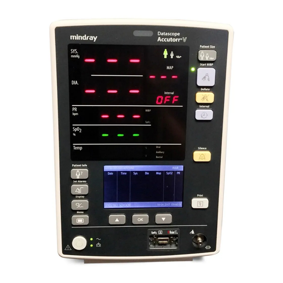
Controls and Indicators Front Panel Front Panel FIGURE 2-1 Accutorr V Front Panel NOTE: The numbers in parentheses ( ) refer to the items described as follows and shown in Figures 2-1 through 2-3. 1. Alarm lamp Flashes red for a high priority alarm and shows continuous yellow for a low priority alarm. - Page 25 The value of systolic pressure is obtained by the NIBP module. When no other LEDs illuminate and the SYS LED displays three (3) flashing dashes and the LCD display (17) is blank, the Accutorr V is in the standby state. 3. Mean pressure (MAP) The value of mean pressure is obtained by the NIBP module.
- Page 26 Moves the cursor down within the LCD display (17). 20. SpO Connector Used to attach an SpO sensor to the Accutorr V. 21. Patient size indicator Patient sizes include adult, pediatric, or neonate from left to right. 22. NIBP status indicator •...
- Page 27 32. Temperature Unit indicator The current temperature unit. 33. PRINT key Starts or stops the recorder. 34. NIBP connector Used to attach the specified NIBP hose to the Accutorr V. 2 - 6 0070-10-0699-02 Accutorr V Operating Instructions...
-
Page 28: Rear Panel
OFF. Refer to Section 3.16.1 for turning BARCODE POWER to OFF. 39. Nurse call connector Provides compatible communication from the Accutorr V to the hospital’s nurse call system. NOTE: All equipment attached to the communications ports on the Accutorr V must meet the requirements as specified in EN 60601-1-1. -
Page 29: Recorder Module
43. AC power input connector Connects the monitor to the AC power through a 3-core power cable. Recorder Module FIGURE 2-3 Accutorr V — Recorder Module 44. Print button Prints the PLETH curve or the trend data on the current display. 45. Paper outlet Recorder feeds paper out of slot. -
Page 30: Operation
SpO2 Measurements ..................3-26 Temperature Measurement ................3-34 Recorder ....................... 3-39 Setting The Clock (Date and Time) ..............3-40 Battery Operation................... 3-41 Creating a User Configuration ................. 3-42 Status and Error Codes ................... 3-47 Accutorr V Operating Instructions 0070-10-0699-02 3 - 1... -
Page 31: Introduction
This section of the Operating Instructions provides guidelines and step-by-step instructions for proper operation of the Accutorr V. The numbers in parentheses ( ) refer to the items described in Chapter 2.0 , “Controls and Indicators” and shown in Figures 2-1 through 2-3. - Page 32 8. If the optional Temperature module kit is installed, test the predictive thermometer by removing the probe from its holder. 9. Verify that the message “Temp Warming Up” displays, followed by the message “Predictive Temp Ready” and a double beep. Accutorr V Operating Instructions 0070-10-0699-02 3 - 3...
-
Page 33: Standby And Power Off
3.4.4 Selecting a Configuration When power to the Accutorr V is turned on, it automatically loads one of three configurations. • The FACTORY DEFAULT (or FACTORY CONFIG) is installed by the factory and cannot be modified. - Page 34 (19) to highlight a configuration to load. 4. Once the choice is highlighted, press (18) to select it. 5. Press (12) to display the SYSTEM SETUP dialog. 6. Press (12) again to display the main screen. Accutorr V Operating Instructions 0070-10-0699-02 3 - 5...
-
Page 35: Patient Setup
Patient Setup Operation Patient Setup 3.5.1 Entering Patient Information Patient information in the Accutorr V monitor consists of the PATIENT ID and the PATIENT TYPE as shown in FIGURE 3-4. FIGURE 3-4 Example PATIENT INFORMATION Dialog To enter patient information: 1. -
Page 36: Quick Admit
Select patient size using one of the two methods: • Press (9) to display the PATIENT INFORMATION dialog (see Section 3.5.1). • Press (23) as follows. Adult Neonate Pediatric FIGURE 3-6 Patient Size Graphics and Indicators (21) Accutorr V Operating Instructions 0070-10-0699-02 3 - 7... -
Page 37: Setting Initial Cuff Inflation Pressure
(12) to display the SYSTEM SETUP dialog as shown in FIGURE 3-7. 2. Press (16) or (19) to highlight MAINTENANCE. FIGURE 3-7 SYSTEM SETUP Dialog 3. Once MAINTENANCE is highlighted, press (18) to display the MAINTENANCE dialog as shown in FIGURE 3-8. 3 - 8 0070-10-0699-02 Accutorr V Operating Instructions... - Page 38 (19) to highlight INITIAL PRESSURE to display the INITIAL PRESSURE dialog as shown in FIGURE 3-10. Once INITIAL PRESSURE is highlighted, press (18) select it. FIGURE 3-10 Example NIBP Cuff Initial Pressure Dialog Accutorr V Operating Instructions 0070-10-0699-02 3 - 9...
- Page 39 INITIAL PRESSURE dialog to the NIBP TOOLS dialog. NOTE: Select CANCEL and then press (18) to cancel the operation and exit the INITIAL PRESSURE dialog without changing the initial pressure values. 3 - 10 0070-10-0699-02 Accutorr V Operating Instructions...
-
Page 40: Manual Nibp Measurements
Manual NIBP Measurements Manual NIBP Measurements The Accutorr V calculates NIBP values using the oscillometric method of noninvasive blood pressure measurement. These measurements correspond to comparisons with auscultatory values, measured using the fifth Korotkoff sound within ANSI/AAMI SP10 standards for accuracy. - Page 41 The cuff begins to inflate to the selected cuff pressure. After reaching the selected pressure, the cuff begins to slowly deflate, and the Accutorr V collects oscillometric pulsations. If the unit detects inadequate initial cuff inflation, the unit retries with a higher inflation pressure (+50 mmHg in the adult and pediatric modes;...
-
Page 42: Nibp Pressure Limit Fail Safe
3.6.3 Automatic Retry If an NIBP measurement fails, the Accutorr V retries measuring up to three times. The message “NIBP RETRY” is displayed after the cuff deflates. If the measurement fails all three retries, the LCD Display (17) shows the Sys, Dia, and Map values as “XXX” and PR as “–” if not providing the pulse rate. -
Page 43: Automatic Nibp Measurements (Interval Mode)
To take an immediate measurement and to reactivate the Interval mode, press (24). The Accutorr V continues the interval mode. For example, if the interval was set to 30 minutes, the next timed measurement will be 30 minutes after pressing... -
Page 44: Changing The Interval Setting
For example: The interval time is set to 60 minutes. Thirty minutes have elapsed since the last timed automatic measurement and the interval time is changed to 10 minutes. Once the interval time is entered, the Accutorr V will take an automatic NIBP measurement in 10 minutes and then once every 10 minutes. -
Page 45: Automatic Retry
3.7.6 Automatic Retry If an NIBP measurement fails, the Accutorr V retries measuring up to three times. The message “NIBP RETRY” is displayed after the cuff deflates. If the measurement fails all three retries, the LCD Display (17) shows the Sys, Dia, and Map values as “XXX” and PR as “–” if not providing the pulse rate. -
Page 46: Alarms
Operation Alarms Alarms The Accutorr V provides HI (high) and LO (low) alarm limit settings for systolic, diastolic, MAP, pulse rate, and SpO . An alarm violation occurs when one or more patient parameters equals or exceed the specified alarm limits. - Page 47 Neonate Off, 51–100 DPM SpO Adult 50–99 %SpO Pediatric 50–99 Neonate 50–99 DPM SpO Pulse Rate High Adult Off, 2–254 Pediatric Neonate DPM SpO Pulse Rate Low Adult Off, 0–252 Pediatric Neonate 3 - 18 0070-10-0699-02 Accutorr V Operating Instructions...
-
Page 48: Alarm Violations
If the message “ALARM DISABLED!” is shown on the LCD Display (17), one or more alarms is OFF as shown for the ALM HI in FIGURE 3-11. To view the alarm settings, press (10). Accutorr V Operating Instructions 0070-10-0699-02 3 - 19... -
Page 49: Pausing And Silencing Alarms
The alarm tone returns if the next measurement value violates the selected limits. NOTE: The Accutorr V counts down time remaining for the alarm pause in the Trend display. • Press (29) for two (2) seconds or more to silence the alarm. The alarm tone returns after the next measurement value that violates the selected limits. -
Page 50: Viewing And Deleting Stored Trend Data
Storing Measurements The Accutorr V automatically stores measurements in trend memory. It stores a maximum of 1,200 rows of data. When the trend memory is full, the Accutorr V automatically deletes the oldest data for the currently displayed patient. The Accutorr V stores SpO and monitor mode Temp values once every 30 seconds and when an NIBP measurement is acquired. -
Page 51: Reviewing And Deleting Stored/Trend Data
Viewing and Deleting Stored Trend Data Operation NOTE: When the time or date settings in the Accutorr V are changed, the monitor saves the new data with the new time and/or date, and trend data displays according to the actual saved time sequence. -
Page 52: Deleting Trend Data
2. Once OK is highlighted, press (18) to accept the selections and return to the Trend List Display. NOTE: Select CANCEL and then press (18) to cancel the any changes or deletions. Accutorr V Operating Instructions 0070-10-0699-02 3 - 23... -
Page 53: Common Setup
• Set the LCD contrast and brightness (refer to Section 3.10.2). 3.10.2 Setting the LCD Brightness and Contrast To adjust the brightness or contrast on the Accutorr V LCD Display (17) for optimum viewing: 1. Press (16) or (19) to highlight the contrast or brightness selection field. - Page 54 Any changes made to LCD BRIGHT and LCD CONTRAST remain when the monitor is turned off and then on again. NOTE: There is no setting item “LCD CONTRAST” on the color LCD display. Accutorr V Operating Instructions 0070-10-0699-02 3 - 25...
-
Page 55: Spo Measurements
3.11 Measurements To obtain SpO measurements and SpO Heart Rate from the Accutorr V with an optional module, see: section 3.11.2 for units with Nellcor SpO , section 3.11.3 for units with Masimo SpO , and section 3.11.4 for units with DPM SpO The LCD Display (17) can display a normalized PLETH waveform from SpO data. - Page 56 • Do not drop on the floor, or jolt the sensor(s). Between use, store the sensors in the accessory pouch, or coil the sensor cable and store on the side of the Accutorr V rolling stand using the optional cable retainer. For accessory part number information see section 5.0, “Accutorr V Accessories”.
-
Page 57: Sequence For Establishing Spo With Nellcor Pulse Oximetry
Nellcor® Oxisensor® patient dedicated adhesive sensors. Use of other oxygen transducers may cause improper oximeter performance. CAUTION: Excessive ambient light may cause inaccurate SpO2 measurements. Cover the sensor with opaque materials. 3 - 28 0070-10-0699-02 Accutorr V Operating Instructions... -
Page 58: Nellcor ® Sensors
LNCS® patient dedicated adhesive sensors and MASIMO PC Series Patient Cable. Use of other oxygen transducers may cause improper oximetry performance. CAUTION: Excessive ambient light may cause inaccurate SpO2 measurements. Cover the sensor with opaque materials. Accutorr V Operating Instructions 0070-10-0699-02 3 - 29... - Page 59 Pulse Rate LED (6). 3. If needed, adjust the beep volume. See Section 3.10.1, “Setting the Alarm Volume, Key Volume, and Pulse Volume, and NIBP End Tone Volume”, for details on adjusting the beep volume. 3 - 30 0070-10-0699-02 Accutorr V Operating Instructions...
-
Page 60: Masimo ® Sensors And Patient Cable
Oximetry Sensitivity Mode and Post Averaging Time The Accutorr V sensitivity mode for SpO is set to normal and the averaging of the saturation, pulse rate, and signal strength measurements for SpO is set to 8 seconds. - Page 61 4. Align the key slot on the connector on the end of the SpO extension cable with the receptacle on the right side panel of the Accutorr V. Push the connector into the receptacle until a “click” is heard. The SpO measurement displays when the Accutorr V detects that the sensor is connected to the patient.
- Page 62 Perform frequent site checks to verify skin integrity is not compromised. CAUTION: When using the Accutorr V equipped with SpO , use only Mindray supplied oxygen transducers and patient cables. Use of other oxygen transducers may cause improper oximeter performance.
-
Page 63: Temperature Measurement
The Accutorr V automatically enters the predict mode when the probe is replaced in the probe sheath. MONITOR MODE: In MONITOR mode, the patient’s temperature is obtained in 3 to 5 minutes and the temperature reading is continuously shown as long as the probe is kept at the measurement position and the patient’s temperature is within the measuring range. -
Page 64: Applying A Probe Cover (Smartemp)
Taking an Oral Temperature Measurement To measure Oral Temperature. 1. Verify that the oral/axillary probe is connected to the probe connector, and the indicator lamp illuminates to indicate that TEMP module is operating. Accutorr V Operating Instructions 0070-10-0699-02 3 - 35... -
Page 65: Taking An Axillary Temperature Measurement
Check that the probe tip is completely surrounded by the axillary tissue. Lower the patient’s arm so that it is tightly placed at the patient side. Keep the patient’s arm and the probe in place throughout the measurement. 3 - 36 0070-10-0699-02 Accutorr V Operating Instructions... -
Page 66: Measuring Rectal Temperature
3/4" (1.25 to 2 cm) for adults and 1/4" to 1/2" (0.5 to 1.25 cm) for children. A lubricant may be used if desired. The measurement will proceed similarly to the oral measurement, and the final reading will be displayed when the display stops flashing. Accutorr V Operating Instructions 0070-10-0699-02 3 - 37... - Page 67 Always store in the sheath for the protection of the probe and to reset the temperature module. NOTE: The thermometer will not take a reading if the patient’s temperature is less than 6°F (3.3°C) above the ambient temperature. 3 - 38 0070-10-0699-02 Accutorr V Operating Instructions...
-
Page 68: Recorder
Operation Recorder 3.13 Recorder The Accutorr V provides a permanent record of patient data using the recorder. • To print the data on the current display (5 lines of data), press (33) for less than 2 seconds (1 beep tone). -
Page 69: Setting The Clock (Date And Time)
User Configuration. There are six (6) properties to set in the clock dialog: DATE FORMAT, YEAR, MONTH, DAY, HOUR, and MINUTE. NOTE: The Accutorr V always displays time in a 24-hour format. FIGURE 3-25 Example TIME SETUP Dialog To set the time and date: 1. -
Page 70: Battery Operation
AC receptacle. When the unit is plugged into an AC receptacle, the Battery status indicator (15) is always illuminated. Maximum battery recharge time is 4.5 hours for Lithium ion with the Accutorr V in standby mode or off, and 6 hours in normal running mode (not in Standby mode). -
Page 71: Creating A User Configuration
Creating a User Configuration Operation 3.16 Creating a User Configuration The operator can set custom default settings. Each time the Accutorr V is turned on, it will use the User Configuration (custom default settings). To create a User Configuration: 1. Press (12) to display the SYSTEM SETUP dialog FIGURE 3-7. -
Page 72: Turning Barcode Power On Or Off
When the RS-232 connector is used for DIAP, barcode power must be set to OFF. 3.16.2 Selecting a Language 1. Follow steps 1 to 18 above to access the USER MAINTENANCE dialog as shown in FIGURE 3-28. Accutorr V Operating Instructions 0070-10-0699-02 3 - 43... -
Page 73: Turning Alarm Tones Off
9. In steps 1 through 4 of Section 3.10.1, set the ALARM VOL to 0. 3.16.4 Sensor Off When SPO2 SENSOR OFF is set to OFF, the Accutorr V disables all alarm indications related to the SpO sensor off alarm. -
Page 74: Setting A Default Power-On Configuration
3.16.6 Setting a Default Power-on Configuration The operator can select the default power-on configuration. Each time the Accutorr V is turned on, it will use that default configuration. To select a default power-on configuration: 1. Press (12) to display the SYSTEM SETUP dialog FIGURE 3-7. - Page 75 (18) select it. 23. Press (16) or (19) to highlight OK or CANCEL. 24. Once the OK or CANCEL is highlighted, press (18) select it and return to the USER MAINTENANCE dialog. 3 - 46 0070-10-0699-02 Accutorr V Operating Instructions...
-
Page 76: Status And Error Codes
, but not RECORDER (for RECORDER, see Section 3.17.9). ## stands for patient category, i.e., adult, pediatric, or neonate. The “Level” field indicates the alarm level: H means high and L means low. Accutorr V Operating Instructions 0070-10-0699-02 3 - 47... -
Page 77: General Alarm Messages Of Parameter Modules
The “A” field indicates whether all alarm indications can be cleared or not, and the “B” field indicates whether all alarm indications except the alarm message can be cleared or not. The alarm levels are H = high and L = low. 3 - 48 0070-10-0699-02 Accutorr V Operating Instructions... - Page 78 The “A” field indicates whether all alarm indications can be cleared or not, and the “B” field indicates whether all alarm indications except the alarm message can be cleared or not. The alarm levels are H = high and L = low. Accutorr V Operating Instructions 0070-10-0699-02...
-
Page 79: Masimo Spo Module Alarm Messages
The “A” field indicates whether all alarm indications can be cleared or not, and the “B” field indicates whether all alarm indications except the alarm message can be cleared or not. The alarm levels are H = high and L = low. * The alarm level is user-adjustable. 3 - 50 0070-10-0699-02 Accutorr V Operating Instructions... -
Page 80: Nellcor Spo Module Alarm Messages
SPO2 ALM LMT Functional failure Notify hospital technician or service personnel PR ALM LMT ERR Functional failure Notify hospital technician or service personnel SPO2 EXCEED value exceeds the measurement Check patient, notify physician range Accutorr V Operating Instructions 0070-10-0699-02 3 - 51... - Page 81 Replace as necessary Low amplitude sensor on same limb as blood Check sensor placement, move as SPO2 signal pressure cuff necessary Patient has poor perfusion Move sensor to limb with better perfusion, notify physician 3 - 52 0070-10-0699-02 Accutorr V Operating Instructions...
-
Page 82: Smartemp ™ Temp Module Alarm Messages
TEMP module. TEMP WRONG PROBE A TEMP probe not supplied Replace with a TEMP by Mindray DS USA, Inc./ probe Mindray DS Shenzhen Mindray Bio- USA, Inc./Shenzhen Medical Electronics Co., Ltd Mindray Bio-Medical is used. -
Page 83: Recorder Module Alarm Messages
The “A” field indicates whether all alarm indications can be cleared or not, and the “B” field indicates whether all alarm indications except the alarm message can be cleared or not. The alarm levels are H = high and L = low. 3 - 54 0070-10-0699-02 Accutorr V Operating Instructions... -
Page 84: System Alarm Messages
(25) to interrupt a with a higher pressure. measurement and deflate the cuff. BARCODE FAILED The barcode reader failed to read the Use another barcode reader. If failure patient’s barcode. continues, contact service personnel. Accutorr V Operating Instructions 0070-10-0699-02 3 - 55... - Page 85 NEONATAL user configuration is loaded None LOADED successfully. NOTE: The prompt message PULSE SEARCH is for the DPM and Nellcor SpO modules only. NOTE: The prompt message SPO2 MOTION is for the Nellcor SpO module only. 3 - 56 0070-10-0699-02 Accutorr V Operating Instructions...
- Page 86 User Maintenance Introduction....................4-2 Cleaning and Disinfection of the Accutorr V Monitor........... 4-3 Sterilization and Cleaning of Reusable Cuffs ............4-5 Battery Maintenance and Replacement.............. 4-6 Recorder Maintenance ..................4-7 Care and Storage of Thermal Paper..............4-9 Resetting the NIBP ..................4-10 Nurse Call Set-up ...................
-
Page 87: User Maintenance
Introduction This section of the manual outlines routine user maintenance care. The Accutorr V is stable for operation over long periods of time and under normal circumstances should not require technical maintenance beyond that described in this section. However, routine maintenance, calibration, and safety checks are recommended at least once a year, or more often as required by local statutory or hospital administration practice. -
Page 88: Cleaning And Disinfection Of The Accutorr V Monitor
User Maintenance Cleaning and Disinfection of the Accutorr V Monitor Cleaning and Disinfection of the Accutorr V Monitor WARNING: Be sure to shut down the monitor and disconnect all power cords from the outlet before cleaning. The equipment should be cleaned regularly. Please consult your hospital’s policy for the recommended frequency for cleaning and disinfecting equipment. -
Page 89: Decontamination Of The Optional Smartemp ™ Temp Probe
Apply a small amount of detergent to a disposable wipe (paper based) and wipe down the outside of the probe. Discard the wipe appropriately. After waiting 10 minutes, use a clean dry wipe to dry the probe. 4 - 4 0070-10-0699-02 Accutorr V Operating Instructions... -
Page 90: Sterilization And Cleaning Of Reusable Cuffs
Cuffs with Bladders • Do not dry clean the cuff. • Do not use detergent and disinfectant other than 70% ethanol or 70% isopropanol. • Clean and disinfect the cuff according to the instructions. Accutorr V Operating Instructions 0070-10-0699-02 4 - 5... -
Page 91: Battery Maintenance And Replacement
2. Rotate the battery retaining clip away from the battery. 3. Slide out the old battery by pulling on the fabric tab attached to the battery. 4. With the main label facing the back of the Accutorr V, slide the replacement battery in until it clicks into place. -
Page 92: Recorder Maintenance
User Maintenance Recorder Maintenance Recorder Maintenance FIGURE 4-2 Accutorr V — Recorder Module 1. Print button 2. Paper outlet 3. Recorder door Open this door to access the recorder paper. 4. Power indicator 5. Recorder door latch Gently pull down on this latch to open the recorder door. - Page 93 3. Replace the paper roll in the holder with the sensitive (shiny) side of the paper facing upward as shown in FIGURE 4-3. 4. Unroll approximately six (6) inches (15 cm.) of paper. 5. Close the recorder door. 4 - 8 0070-10-0699-02 Accutorr V Operating Instructions...
-
Page 94: Care And Storage Of Thermal Paper
We recommend that if long term archives are required, make a photocopy of the printouts as a back-up. Under normal office filing conditions the printouts should retain acceptable image quality for about five (5) years Accutorr V Operating Instructions 0070-10-0699-02 4 - 9... -
Page 95: Resetting The Nibp
(19) to highlight NIBP TOOLS to display the NIBP TOOLS dialog as shown in FIGURE 4-6. 5. Once NIBP TOOLS is highlighted, press (18) to display the NIBP TOOLS dialog. FIGURE 4-6 NIBP TOOLS Dialog 4 - 10 0070-10-0699-02 Accutorr V Operating Instructions... - Page 96 (19) to highlight NIBP RESET to display the INITIAL PRESSURE dialog as shown in FIGURE 4-6. Once NIBP RESET is highlighted, press (18) reset the NIBP. While the NIBP is setting, the prompt message “RESETTING… ” displays. Accutorr V Operating Instructions 0070-10-0699-02 4 - 11...
-
Page 97: Nurse Call Set-Up
16. Once an ALM LEV is highlighted, press to select it. 17. Press to highlight either TECH or PHYS for ALM TYPE. 18. Once an ALM TYPE is highlighted, press to select it. 4 - 12 0070-10-0699-02 Accutorr V Operating Instructions... -
Page 98: Accutorr V Accessories
Accutorr V Accessories Accessories....................5-2 Accutorr V Operating Instructions 0070-10-0699-02 5 - 1... -
Page 99: Accessories
Size 3: 7 – 10 cm, box of 10 0683-23-0003 Size 4: 9 – 13 cm, box of 10 0683-23-0004 Size 5: 12 – 17 cm, box of 10 0683-23-0005 Hose P/N 0683-04-0003 is required. 5 - 2 0070-10-0699-02 Accutorr V Operating Instructions... -
Page 100: Oximetry Sensors And Accessories
518B Adult, pediatric, neonate (multi-sites) reusable Wrap type with 1.1m. 518B-30-72107 cable 512F Adult reusable Finger Clip type with 1.1m. cable 512F-30-28263 512H Pediatric reusable Finger Clip type with 1.1m. cable 512H-30-79061 Envitec DPM SpO2, Adult Ear Sensor 0010-10-12392 Accutorr V Operating Instructions 0070-10-0699-02 5 - 3... -
Page 101: Pulse Oximetry-Masimo Set Lnop Spo
II NeoPt-L-Preterm Neonatal L single patient adhesive 0600-00-0098 sensors-for patients less than 1 kg. (pkg of 20) Posey wraps for Preterm Neonatal L single patient adhesive 0600-00-0097 sensors (pkg of 12) Clothing clips (pkg of 5) 0600-00-0084 5 - 4 0070-10-0699-02 Accutorr V Operating Instructions... -
Page 102: Pulse Oximetry-Masimo Set Lncs Spo
SmarTemp Temperature Accessories DESCRIPTION PART NUMBER TEMP sheath (oral/auxiliary) M09A-20-62062 TEMP sheath (rectal) M09A-20-62062-51 TEMP probe (oral/auxiliary) 801-6006-00009-00 TEMP probe (rectal) 6006-30-39599 Disposable probe cover (20 pcs) M09A-20-62124 Disposable probe cover (2000 pcs) M09A-30-62128 Accutorr V Operating Instructions 0070-10-0699-02 5 - 5... -
Page 103: Nurse Call Connector
Power Cord, 250 Volt (Brazil) 009-001075-00 5.1.9 Mounting Assemblies DESCRIPTION PART NUMBER Mounting kit for Accutorr V to rolling stand (Includes mounting 6101-30-46696 head kit, and mounting bracket) Mounting head kit (For rolling stand) 115-002451-00 Mounting bracket (For wall mount or rolling stand) - Page 104 Spare Latch assembly for rolling stand 115-009638-00 Accutorr V Wall Mount Bracket Mounting Screw Sample Wall Mount FIGURE 5-1 Accutorr V Wall Mount Kit (P/N: ACTVWALLMT FIGURE 5-2 Rolling Stand with Mounting Bracket (P/N: ACTVROLLSTD Accutorr V Operating Instructions 0070-10-0699-02...
- Page 105 Accessories Accutorr V Accessories This page intentionally left blank. 5 - 8 0070-10-0699-02 Accutorr V Operating Instructions...
-
Page 106: Appendix
Electromagnetic Compatibility ................6-15 Indirect Blood Pressure Measurements and Associated Errors ....... 6-19 Precautions With Using Automatically Cycled Blood Pressure Cuffs....... 6-20 User Verification Of The Accutorr V NIBP Measurements ........6-21 Warranty....................... 6-22 Manufacturer’s Responsibility ................6-23 Accutorr V Operating Instructions... -
Page 107: How To Get Assistance
Warranty questions should be directed to a local representative. A list of offices, along with their phone numbers, is provided at the end of this manual. 6 - 2 0070-10-0699-02 Accutorr V Operating Instructions... -
Page 108: Specifications
Less than 40 seconds average at 80 BPM with 180mmHg pump up pressure, without retries, motion artifact or arrhythmia with standard adult cuff on a healthy individual. Cycle time is affected by arm size and wrapping technique. Accutorr V Operating Instructions 0070-10-0699-02 6 - 3... -
Page 109: Pulse Rate
500 cc’s is reduced from a pressure of 150 mmHg to a pressure of 5 mmHg in a maximum of 5 seconds. 6 - 4 0070-10-0699-02 Accutorr V Operating Instructions... -
Page 110: Temperature
When sensors are used on neonatal subjects as recommended, the specified accuracy range ± is increased by 1 digit, to account for the theoretical effect on oximeter measurements of fetal hemoglobin in neonatal blood. Accutorr V Operating Instructions 0070-10-0699-02 6 - 5... -
Page 111: Masimo Performance Specifications
Accuracy Saturation during Motion Conditions Adults / Pediatrics / Neonates 70% – 100% ± 3 <70% unspecified Low Perfusion Performance >0.02% Pulse Amplitude and %Transmission >5% %SpO Accuracy: ±2 digits Pulse Accuracy:±3 digits 6 - 6 0070-10-0699-02 Accutorr V Operating Instructions... - Page 112 0.02% and a % transmission of greater than 5% for saturation’s ranging from 70 to 100%. This variation equals plus or minus one standard deviation. Plus or minus one standard deviation encompasses 68% of the population. Accutorr V Operating Instructions 0070-10-0699-02 6 - 7...
-
Page 113: Dpm Performance Specifications
1 second Wavelength of light emitted by red: 660 nm the sensors infrared 905 nm 6.2.11 Battery Battery Type: Lithium Number of Batteries: Battery Voltage: 11.1 VDC nominal Battery Capacity: 4.6 Amp-Hour 6 - 8 0070-10-0699-02 Accutorr V Operating Instructions... - Page 114 Recharge Time: Maximum battery recharge time is 4.5 hours for Lithium ion with the Accutorr V in standby mode or off, and 6 hours in normal running mode (not in Standby mode). Accutorr V Operating Instructions...
-
Page 115: Real Time Clock
6.2.13 Physical Characteristics • Size (maximum): Dimensions: Width 168 mm (6.614 inches) Height 246 mm (9.685 inches) Depth 166 mm (6.535 inches) Weight (full configuration, including battery): <3.5 kilograms <7.71 pounds 6 - 10 0070-10-0699-02 Accutorr V Operating Instructions... -
Page 116: Recovery From Power Loss
6.3.1 Alarm Restoration from Power Loss If the Accutorr V is turned off or loses power for less than 60 seconds, the alarm settings in use at that time are restored when it is turned on. If the Accutorr V is turned off or loses power for more than 60 seconds, the default power-on configuration is restored (see Section 3.16.6, “Setting a Default Power-on Configuration”). -
Page 117: Environmental Characteristics
Environmental Characteristics Appendix Environmental Characteristics • Operating: Temperature: 0°C to 40°C, 32°F to 104°F (Accutorr V & Recorder) 10°C to 40°C, 50°F to 104°F (Predictive Thermometer) Humidity: 15 to 95% max, non-condensing. Altitude: -1,250 to 10,000 feet (-381 to 3048 meters, 70.0 kPa to 106 kPa) -
Page 118: Electrical Ratings
Appendix Electrical Ratings Electrical Ratings Voltage: 100 – 240 VAC Current: 0.85 – 0.5 A Frequency: 60 / 50 Hz Power Consumption: 40 W, maximum Accutorr V Operating Instructions 0070-10-0699-02 6 - 13... -
Page 119: Agency Compliance
Radiated and Conducted Emissions EN 55011:2007 +A2:2007 Sinusoidal Vibration IEC 60068-2-6:1995 Usability IEC 60601-1-6:2004 Clinical Thermometers Part 3: Performance EN 12470-3:2000 of Compact Electrical Thermometers (non- predictive and predictive) with maximum device 6 - 14 0070-10-0699-02 Accutorr V Operating Instructions... -
Page 120: Electromagnetic Compatibility
GUIDANCE AND DECLARATION - ELECTROMAGNETIC EMISSIONS The Accutorr V is intended for use in the electromagnetic environment specified in the table. The customer or the user of the Accutorr V should assure that it is used in such an environment. EMISSIONS... - Page 121 GUIDANCE AND DECLARATION - ELECTROMAGNETIC IMMUNITY The Accutorr V is intended for use in the electromagnetic environment specified in the table. The customer or the user of the Accutorr V should assure that it is used in such an environment. IMMUNITY...
- Page 122 GUIDANCE AND DECLARATION - ELECTROMAGNETIC IMMUNITY The Accutorr V is intended for use in the electromagnetic environment specified in the table. The customer or the user of the Accutorr V should assure that it is used in such an environment. IMMUNITY...
- Page 123 RECOMMENDED SEPARATION DISTANCES BETWEEN PORTABLE AND MOBILE RF COMMUNICATIONS EQUIPMENT AND THE ACCUTORR V The Accutorr V is intended for use in an electromagnetic environment in which radiated RF disturbances are controlled. The customer or the user of the Accutorr V can help prevent...
-
Page 124: Indirect Blood Pressure Measurements And Associated Errors
When the patient is supine, on a flat surface, the arm is near enough to the heart level so no adjustment of the NIBP readings will be necessary. Accutorr V Operating Instructions 0070-10-0699-02 6 - 19... -
Page 125: Precautions With Using Automatically Cycled Blood Pressure Cuffs
Irregular cardiac rhythm changes the stroke volume from beat to beat. This changing stroke volume may increase the time it takes the Accutorr V to make a measurement. The Accutorr V system will take up to four successive attempts to obtain a measurement. -
Page 126: User Verification Of The Accutorr V Nibp Measurements
Regular service to blood pressure equipment will help ensure accurate measurements. Consult the service manual for appropriate information. If the accuracy of the Accutorr V is questionable, check it (the Accutorr V) with a manometer. See the Calibration Section of the Accutorr V Service Manual. -
Page 127: Warranty
Mindray DS USA Inc./ Shenzhen Mindray Bio-Medical Electronics Co., Ltd’s option at the factory or at an authorized distributor, any product which shall under normal use and service appear to the Company to have been defective in material or workmanship. -
Page 128: Manufacturer's Responsibility
• the electrical installation of the relevant room complies with the appropriate requirements; and • the equipment is used in accordance with the Instructions for use. Accutorr V Operating Instructions 0070-10-0699-02 6 - 23... - Page 129 Rev 12.0 March, 2015 0070-10-0699-02...
- Page 130 Hoevelaken • The Netherlands • Tel: +31 33 25 44 911 • Fax: +31 33 25 37 621 Mindray (UK) Limited • 3 Percy Road • St. John’s Park • Huntingdon • Cambridgeshire PE29 6SZ • United Kingdom • Tel: 01480 416840 • Fax: 01480 436588 Mindray Medical France SARL •...
Need help?
Do you have a question about the Accutorr V and is the answer not in the manual?
Questions and answers