
Subscribe to Our Youtube Channel
Related Manuals for Mindray Datascope AS 3000


Summary of Contents for Mindray Datascope AS 3000
- Page 1 s e r v i ce m a n u a l Datascope ™ A n e s t h e s i A D e l i v e r y s y s t e m...
- Page 2 s e r v i ce m a n u a l Datascope ™ A n e s t h e s i A D e l i v e r y s y s t e m...
- Page 3 S-2000 are registered trademarks of Dräger Medical. © Copyright Mindray DS USA, Inc., 2008. All rights reserved. Contents of this publication may not be reproduced in any form without permission of Mindray DS USA, Inc. AS3000™ Service Manual...
-
Page 4: Table Of Contents
Table of Contents Foreword ...............................vii Warnings, Cautions and Notes ........................vii Warnings ..............................vii Cautions ...............................viii Notes ................................ix Theory of Operation .....................1 - 1 Introduction ..............................1 - 1 Microprocessor-controlled Ventilator......................1 - 2 Components............................... 1 - 3 Front View ............................1 - 3 Side View............................ - Page 5 Table of Contents Manual Breathing Bag ....................... 1 - 39 Absorber .......................... 1 - 39 Inspiratory and Expiratory Valves ....................1 - 39 APL (Airway Pressure Limiting) valve .................... 1 - 39 Installation Guide ......................2 - 1 Delivery of The New Anesthesia Machine ...................... 2 - 1 Assembly ..............................
- Page 6 Table of Contents Breathing System ..........................4 - 6 Breathing System Parts List......................4 - 11 Electric Box............................4 - 12 Electric Box Parts List........................4 - 12 Gas Circuit Box..........................4 - 13 Gas Circuit Box Parts List......................4 - 13 User Interface............................
- Page 7 Table of Contents System Self Test......................... 6 - 15 Leak/Safety Valve Test....................... 6 - 15 Leak Test ..........................6 - 17 Compliance Test ........................6 - 20 Manual Leak Test ........................6 - 21 Oxygen Sensor Calibration ......................6 - 22 Pneumatic Leak Tests ..........................
- Page 8 Table of Contents Cleaning and Sterilizing the Breathing System and Components.............. 6 - 39 Preoperative Checklist ..........................6 - 39 Phone Numbers and How To Get Assistance....................6 - 47 Warranty ........................7 - 1 Warranty Statements ........................... 7 - 1 Disclaimers ..............................
- Page 9 Table of Contents This page intentionally left blank. 0070-10-0683 AS3000™ Service Manual...
-
Page 10: Foreword
Foreword Introduction Foreword This Service Manual is intended as a guide for technically qualified personnel performing repair and calibration procedures. Warnings, Cautions and Notes Please read and adhere to all warnings, cautions and notes listed here and in the appropriate areas throughout this manual. A WARNING is provided to alert the user to potential serious outcomes (death, injury, or serious adverse events) to the patient or the user. -
Page 11: Cautions
Introduction Cautions WARNING: Compressed gasses are considered Dangerous Goods/ Hazardous Materials per I.A.T.A. and D.O.T. regulations. It is a violation of federal and international law to offer any package or over pack of dangerous goods for transportation without the package being appropriately identified, packed, marked, classified, labeled and documented according to D.O.T. -
Page 12: Notes
Notes Introduction CAUTION: The bellows dome cannot be autoclaved. CAUTION: Do not clean the machine while it is on and/or plugged in. CAUTION: Pressing “Quit” at any time during the procedure will cancel the session's settings and reload the previously-stored calibration coefficients. - Page 13 Introduction Notes This page intentionally left blank. 0070-10-0683 AS3000™ Service Manual...
-
Page 14: Theory Of Operation
Theory of Operation Introduction The AS3000 is a continuous flow anesthesia system which offers manual or automatic ventilation, easily adjustable fresh gas delivery, anesthetic agent delivery, ventilation monitoring, convenient ergonomics, and state-of-the-art safety systems. The components of the AS3000 Anesthesia System are described this chapter. AS3000™... -
Page 15: Microprocessor-Controlled Ventilator
Microprocessor-controlled Ventilator Theory of Operation Microprocessor-controlled Ventilator The Microprocessor-controlled ventilator, with its dedicated Breathing System, allows time- controlled, pressure limited, constant volume ventilation for all patient groups within a tidal volume range of 40 mL (4 kg infant) to 1400 mL (large adult). Time-controlled, pressure limited, and compliance compensated constant volume ventilation is provided through the Controlled Mandatory Ventilation (CMV) mode. -
Page 16: Components
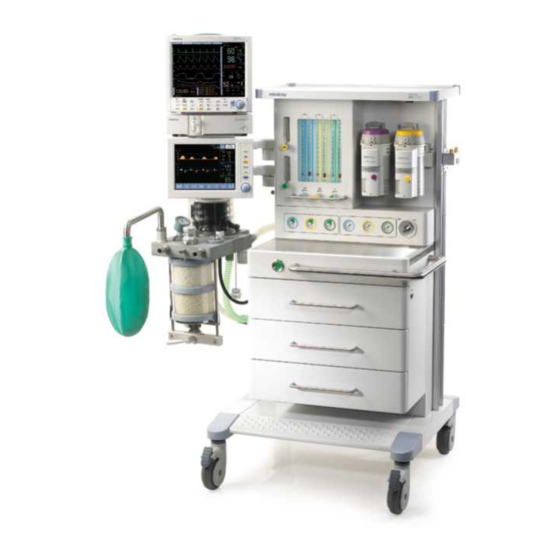
Theory of Operation Components Components 1.3.1 Front View FIGURE 1-2 AS3000 Front View 1. Monitor Arm The Monitor Arm provides support for a bedside monitor. It can easily rotate for more convenient viewing. 2. User Interface The display of the user Interface provides waveforms, numeric data and menu tabs. The keys and Navigator Knob enable the user to power up the system, silence alarms, access menu tabs, and switch between manual and mechanic ventilation. - Page 17 Components Theory of Operation 3. UI Arm The UI Arm provides support for the user interface assembly. It can easily rotate for more convenient viewing. 4. Oxygen Sensor The Oxygen Sensor monitors the oxygen concentration of the inspired gas of the Breathing System.
-
Page 18: Side View
Theory of Operation Components 1.3.2 Side View FIGURE 1-3 AS3000 Side View 12. Upper Mainframe Subassembly The Upper Mainframe Subassembly provides support for the pressure gauges, the Flowmeter, the gas box assembly, the mains supply assembly, and the YOKE assembly. 13. - Page 19 Components Theory of Operation 14. Auxiliary Gas Outlet Assembly The Auxiliary Gas Outlet Assembly provides the patient with auxiliary oxygen and air mixtures (of different concentrations). It also contains an O connection for use with other equipment. 15. Breathing System Interface The Breathing System Interface provides a connection interface for gas signal acquisition between the Breathing System and gas circuit.
-
Page 20: Rear View
Theory of Operation Components 1.3.3 Rear View FIGURE 1-4 AS3000 Rear View 24. Top Shelf Assembly The Top shelf Assembly includes the work light and its switch. It also serves as a storage area. 25. Gas Input Assembly The Gas Input Assembly allows gas in the pipeline and backup gas cylinder to enter the AS3000 for regulation. -
Page 21: Other Components (Not Identified In Graphics)
Components Theory of Operation 26. Vaporizer Storage Mount The Vaporizer Storage Mount provides the AS3000 with auxiliary placement for a vaporizer. 27. Mains Supply Assembly The Mains Supply Assembly attaches the AS3000 to an external AC wall outlet. It also supplies power throughout the unit. -
Page 22: Breathing System
Theory of Operation Components 37. Bellows Assembly The AS3000 employs ascending ventilation bellows, in which mixed gas is stored. Drive gas supplied by the ventilator forces the bellows to descend sending mixed gas into the inspiratory passage of patient's airway. If a patient's airway suffers from gas leakage, the bellows will collapse, informing the operator of a possible problem. -
Page 23: Adjustable Alarms
Components Theory of Operation 1.3.7 Adjustable Alarms Minimum and maximum alarm limits can be set for Peak Pressure, Mean Pressure and FiO Minimum alarm limits can be set for Tidal Volume and Minute Volume. Exceeding the peak pressure alarm limit automatically halts the inspiratory phase preventing airway pressure from exceeding the high alarm setting. -
Page 24: Electrical Supply
Theory of Operation Electrical Supply Electrical Supply 1.4.1 Electrical components Anesthesia Ventilator UI 10.4” TFT-LCD Backlight Inverter Amplifier for Keypad audio alarm PC104 Communication Knob and Interface Cable Ventilator Control and Drive Switch PWR MNG Ctrl & Amplifier DC/DC Protect Switch Power Supply AC/DC... -
Page 25: Ventilator Control And Drive
Ventilator Control and Drive Theory of Operation Ventilator Control and Drive 1.5.1 BDU (Basic Digital Unit) The BDU serves as the active ventilator control. The BDU controls the actions of the PEEP, calibration, and proportional valves, and reads the signal flow, and pressure sensors and valves FIGURE 1-6 BDU Control Board, Top View 1 - 12... - Page 26 Theory of Operation Ventilator Control and Drive FIGURE 1-7 BDU Control Board, Bottom View AS3000™ Service Manual 0070-10-0683 1 - 13...
-
Page 27: Amplifier Board
Ventilator Control and Drive Theory of Operation 1.5.1.1 Amplifier Board FIGURE 1-8 Amplifier Board, Top View FIGURE 1-9 Amplifier Board, Bottom View 1 - 14 0070-10-0683 AS3000™ Service Manual... - Page 28 Theory of Operation Ventilator Control and Drive Sensor Input, S4 NAME FUNCTION Sensor Input - Sensor Input - Sensor Input + Sensor Input + DC Power Input, J7 NAME FUNCTION Power Ground Controller Logic Power P12V Power 12V PWBUS Power Bus 24V Analog Ground A12V Analog 12V...
- Page 29 Ventilator Control and Drive Theory of Operation Signals and Power to Keyboard, J5 (Continued) NAME FUNCTION PWBUS PowerBus PWBUS PowerBus PWBUS PowerBus Ground Ground DC24V DC24V monitor BATV+ Battery monitor /MUTE No connection Ground TTLTX TTL Transmit 232ATX RS232A Transmit 232BTX RS232B Transmit Ground...
- Page 30 Theory of Operation Ventilator Control and Drive Signals and Power to Sensor Board, J30 (Continued) NAME FUNCTION AGND Analog Ground AGND Analog Ground AGND Analog Ground Bus to BDU, J96 NAME FUNCTION 1 - 3 5V Power 4 - 6 Ground Test Point Definition DESIGNATOR...
- Page 31 Ventilator Control and Drive Theory of Operation Test Point Definition DESIGNATOR NAME FUNCTION RANGE -10V Negative Voltage -10V -10V A12V Analogue 12V Power 5V 5VAUX 5V Auxiliary Analogue +10V +10V AD-Inhale Inhale-STATE feedback No activity may indicate open connection from driver to valve (ie.
-
Page 32: Drive Gas Pressure Sensor Board
Theory of Operation Ventilator Control and Drive 1.5.1.2 Drive Gas Pressure Sensor Board FIGURE 1-10 Drive Gas Pressure Sensor Board, Top View FIGURE 1-11 Drive Gas Pressure Sensor Board, Bottom View Pair Board Pair, J1 NAME FUNCTION AGND Analog Ground Pair Pressure of air No connection... -
Page 33: Paw Pressure Sensor Board
Ventilator Control and Drive Theory of Operation 1.5.1.3 PAW Pressure Sensor Board FIGURE 1-12 Paw Pressure Sensor Board, Top View FIGURE 1-13 Paw Pressure Sensor Board, Bottom View Paw Board Paw, J2 NAME FUNCTION AGND Analog Ground Pressure inside airway AR5V No connection No connection... -
Page 34: Breathing System Heater
Theory of Operation Ventilator Control and Drive 1.5.1.4 Breathing System Heater FIGURE 1-14 Breathing System Heater Board, Top View FIGURE 1-15 Breathing System Heater Board, Bottom View NAME FUNCTION Power Ground Controller Power, Output Enable Heater Power Supply No Connection AS3000™... - Page 35 Ventilator Control and Drive Theory of Operation NAME FUNCTION Heater Power Ground Sensor signal Heater Output Test point definition DESIGNATOR NAME FUNCTION Power Ground Controller Power Heater Power input POUT Heater Output Indicating lamp definition DESIGNATOR STATUS FUNCTION Heater Output available GREEN Heater Ready 1 - 22...
-
Page 36: Sensor Board
Theory of Operation Ventilator Control and Drive 1.5.1.5 Sensor Board FIGURE 1-16 Sensor Board, Top View FIGURE 1-17 Sensor Board, Bottom View AS3000™ Service Manual 0070-10-0683 1 - 23... - Page 37 Ventilator Control and Drive Theory of Operation Sensor Board Pair, J1 NAME FUNCTION AGND Analog Ground Pair Pressure of air No connection AR10V No connection PAW, J2 NAME FUNCTION AGND Analog Ground Pressure inside airway AR5V No connection No connection Work Light Power, J11 NAME FUNCTION...
- Page 38 Theory of Operation Ventilator Control and Drive Inspire Valve, J12 NAME FUNCTION 1 - 2 3 - 4 Valexp inspire Valve Drive Man/Auto Valve, J14 NAME FUNCTION Valman Manual/Auto Valve Drive Signals and Power of Sensor Board, J13 NAME FUNCTION A+12V Analogue +12V FL_INS...
-
Page 39: Power Management
Ventilator Control and Drive Theory of Operation 1.5.2 Power Management Power management is located behind the Rear Panel Assembly. This module serves as the voltage supply for the ventilator control and drive BDU, the flowmeter backlight, the work light, the Breathing System Heater, and the charging/discharging control for the battery. FIGURE 1-18 Power Board, Top View FIGURE 1-19 Power Board, Bottom View 1 - 26... - Page 40 Theory of Operation Ventilator Control and Drive Power Board Battery input, J4 NAME FUNCTION Battery Input + Power Ground BATTEST Battery test input DC24V Power input, J3 NAME FUNCTION Power Ground Power Ground Power input Power input DC Power output, J2 NAME FUNCTION Power Ground...
-
Page 41: Battery
Ventilator Control and Drive Theory of Operation Power Control, J2 (Continued) NAME FUNCTION Auxiliary Power Enable CHAR_SIGNAL Charge Status, No connection /MUTE Mute, No connection Power Switch, J5 NAME FUNCTION Ground No Connection PWON Power On Enable, Low active Test Point definitions DESIGNATOR NAME FUNCTION... -
Page 42: Anesthesia System Components
Theory of Operation Anesthesia System Components Anesthesia System Components 1.6.1 Auxiliary Outlets The AS3000 has four auxiliary outlets (120 VAC, 60 Hz, 2A maximum each). There are two 2A fuses for each outlet. 1.6.2 Absorber Heater Wire Board FIGURE 1-20 Absorber Heater Wire Board, Top View FIGURE 1-21 Absorber Heater Wire Board, Bottom View 1.6.3 Work Light Board... - Page 43 Anesthesia System Components Theory of Operation Work light Power, J11 NAME FUNCTION Power No Connection Power Ground Work light switch, J11 NAME FUNCTION Power 24V No Connection Low dim HIGH High dim 1 - 30 0070-10-0683 AS3000™ Service Manual...
-
Page 44: Ventilator Ui
Theory of Operation Ventilator UI Ventilator UI 1.7.1 Keyboard Board FIGURE 1-24 Keyboard Board, Top View AS3000™ Service Manual 0070-10-0683 1 - 31... - Page 45 Ventilator UI Theory of Operation FIGURE 1-25 Keyboard Board, Bottom View 1 - 32 0070-10-0683 AS3000™ Service Manual...
- Page 46 Theory of Operation Ventilator UI Keyboard Signals and Power of Keyboard, J1 NAME FUNCTION ENPW Power Enable, High active Ground /PWON / Power on Enable, Low active DC24V DC24V monitor 5VAUX 5V Auxiliary BATV+ Battery monitor Auxiliary Power Enable /MUTE No connection Ground Ground...
-
Page 47: Display
Ventilator UI Theory of Operation Backlight Power, J2 (Continued) NAME FUNCTION ON/OFF Backlight ENABLE Contrast adjust Power of 232 Isolator, J9 NAME FUNCTION Power 5V No connection Ground COM1/2 NAME FUNCTION 232RXD TO PC104 INPUT 232TXD TO PC104 OUTPUT Ground Test Point Definition DESIGNATOR NAME... -
Page 48: Communication Interface / Rs232 Isolate Board
Theory of Operation Ventilator UI 1.7.3 Communication Interface / RS232 Isolate Board FIGURE 1-26 RS232 Isolate Board, Top View FIGURE 1-27 RS232 Isolate Board, Bottom View RS232 Isolator Power, J3 Name Function Power 5V No connection Ground COM1/2 Name Function 232RXD TO PC INPUT 232TXD TO PC OUTPUT Ground... -
Page 49: Ventilator Pneumatic - O Drive Gas
Ventilator Pneumatic - O Drive Gas Theory of Operation Ventilator Pneumatic - O Drive Gas 1.8.1 Ventilator pneumatic drive Oxygen is the driving gas for the ventilator. In addition to the flowmeter block, a high pressure regulator reduces the supply pressure to 25.4 psi (175 kPa). This pressure represents the drive gas for the ventilator. -
Page 50: The Breathing System
Theory of Operation The Breathing System The Breathing System 1.9.1 CMV mode, inspiration Tidal volume (T Vol.) compensates for variations in gas flow. This is to ensure that the set tidal volume is delivered to the patient. Exp. Valve APL Valve Exp. -
Page 51: Manual Mode, Inspiration
The Breathing System Theory of Operation 1.9.3 Manual mode, inspiration As the breathing bag is compressed, the gas is directed to the patient. Pressures exceeding the set value of the APL Valve will pass through the APL Valve the AGSS. Exp. -
Page 52: Pneumatic Peep
Theory of Operation The Breathing System 1.9.5 Pneumatic PEEP The PEEP valve regulates the pressure at which the exhaust valve opens, therefore the exhaust valve opens only when the pressure exceeds the set PEEP pressure. 1.9.6 Ventilator in Standby When the AS3000 is in the standby mode, monitoring will be inactive, The patient should not be ventilated when the system is in standby mode. - Page 53 The Breathing System Theory of Operation This page intentionally left blank. 1 - 40 0070-10-0683 AS3000™ Service Manual...
-
Page 54: Installation Guide
Installation Guide Delivery of The New Anesthesia Machine The following customer supplied material must be present prior to installation. Missing equipment can result in delays, incomplete installations and/or extra visits. • Compatible emergency O O, and AIR cylinders • Agent vaporizers and key fillers, if not purchased with the AS3000 •... -
Page 55: Assembly
Assembly Installation Guide Assembly NOTE: The AS3000 Breathing System Block is matched to the AS3000 it is attached to by calibration and installation. After removing the Breathing System Block from the Mounting Arm of the AS3000, assure that the Breathing System Block is returned to the same AS3000 that it came from originally. -
Page 56: Attaching The Mounting Arms And User Interface
Installation Guide Assembly 2.2.2.1 Attaching the Mounting Arms and User Interface (see FIGURE 2-1) 1. Remove the mounting arms from small box and install them onto the AS3000 using a 3 mm allen wrench. 2. Remove the keys from the parts box, and unlock the AS3000 drawers and put parts box into top drawer. -
Page 57: Tank Wrench And Pre-Operation Checklist
Assembly Installation Guide 2. Attach the Drive Gas Hose to the designated port on the Breathing System Interface. 3. Attach the Heater Cable to the designated port on the Breathing System Interface. 4. Attach the O Cable to the designated port on the Breathing System Interface. 5. -
Page 58: High Pressure Hoses
Installation Guide Assembly 2. Discard the washers that came with the vaporizer. Use only approved O-rings that come mounted on the vaporizer mounting ports of the AS3000. 3. Mount a mechanical vaporizer to either side of the AS3000 vaporizer mount by placing the vaporizer on the ports and locking down the lever. -
Page 59: Monitoring Products - Mounting And Electrical Connection
Assembly Installation Guide 2.2.11 Monitoring Products - Mounting and Electrical Connection 1. Any monitoring system compatible with the GCX mounting system's swivel head may be mounted to the AS3000’s arm. NOTE: Use of other monitors and mounting hardware is the responsibility of the installer. - Page 60 Installation Guide Assembly NOTE: If the system is going to be used during the calibration, insert the O cell plug into the port from which the oxygen sensor was removed using a push and turn motion. a. Select 21% to enter the 21% oxygen concentration calibration screen. b.
-
Page 61: Installation Checkout Procedure
Installation Checkout Procedure Installation Guide Installation Checkout Procedure Complete each step to verify the functionality of the AS3000 prior to clinical use. Also, perform this checkout after installation, reinstallation, servicing or after any periodic maintenance activity. This checklist does not replace periodic maintenance actions that must be performed to maintain peak performance. - Page 62 Installation Guide Installation Checkout Procedure 5. Check N O, O and AIR Lines for leaks. a. Remove the cylinders from the AS3000. b. Connect the O , AIR and N O hoses to the gas line inlets. NOTE: If a specific gas source is not available, skip the corresponding leak test.
- Page 63 Installation Checkout Procedure Installation Guide 9. Test the O O ratio system (applicable to -02 units only). a. Set all flow control knobs to minimum. b. Set the flow of O to 1 L/min. c. Open the N O flow knob and verify that the N O flow will not increase higher than 3.7 L/min.
- Page 64 Installation Guide Installation Checkout Procedure 11. Perform Leak/Safety Valve Test a. Follow the on-screen instructions. FIGURE 2-3 Leak Test Setup b. Select Continue to start the test. FIGURE 2-4 Safety Valve Test Setup AS3000™ Service Manual 0070-10-0683 2 - 11...
- Page 65 Installation Checkout Procedure Installation Guide FIGURE 2-5 Safety Valve Test in Progress FIGURE 2-6 Safety Valve Test Passed Message c. After 3 seconds, the screen will prompt to the Leak Test. 12. Perform Leak Test 2 - 12 0070-10-0683 AS3000™ Service Manual...
- Page 66 Installation Guide Installation Checkout Procedure a. Follow the on-screen instructions. b. Select Continue to start the test. FIGURE 2-7 Leak Test Setup AS3000™ Service Manual 0070-10-0683 2 - 13...
- Page 67 Installation Checkout Procedure Installation Guide FIGURE 2-8 Leak Test in Progress c. Select Continue to prompt to the Compliance Test. FIGURE 2-9 Leak Test Results 2 - 14 0070-10-0683 AS3000™ Service Manual...
- Page 68 Installation Guide Installation Checkout Procedure 13. Perform Compliance Valve Test a. Follow the on-screen instructions. b. Select Continue to start the test. FIGURE 2-10 Compliance Test Setup FIGURE 2-11 Compliance Test in Progress AS3000™ Service Manual 0070-10-0683 2 - 15...
- Page 69 Installation Checkout Procedure Installation Guide c. Select Continue to prompt to the Normal Screen. FIGURE 2-12 Compliance Test Results 14. Manual Leak Test NOTE: The Manual Leak Test detects smaller leaks than can be detected in the Automatic Leak Test. a.
- Page 70 Installation Guide Installation Checkout Procedure 15. Oxygen Sensor Calibration NOTE: Oxygen Sensor Calibration can be performed in all ventilation modes. NOTE: See ‘‘Periodic Maintenance Schedule of Service Activities’’ on page 6-2 for when to calibrate the oxygen sensor. a. Allow the breathing system to warm up and reach thermal equilibrium (approximately 30-60 minutes).
- Page 71 Installation Checkout Procedure Installation Guide NOTE: If the system is going to be used during the calibration, insert the O cell plug into the port from which the oxygen sensor was removed using a push and turn motion. e. After at least 3 minutes have passed, select the Next button to initiate the calibration process.
- Page 72 Installation Guide Installation Checkout Procedure 16. Proceed based on one of the following two conditions: • If the calibration is successful, the screen shown in FIGURE 2-18 will be displayed, instructing the user to reinstall the oxygen sensor into the Breathing System. Select the Done button to complete the process.
- Page 73 Installation Checkout Procedure Installation Guide e. Set the ventilator controls to: VENTILATOR CONTROLS VENTILATOR SETTINGS Patient Type Adult Ventilation Mode Tidal Volume - V Breath Rate - freq I:E Ratio - I:E Plateau - T PEEP - PEEP f. Select CMV again to begin ventilation. g.
- Page 74 Installation Guide Installation Checkout Procedure c. Attach a Vent Tester between the EXP port and the expiratory hose. d. Set the O flow to 2 L/min and set the N O and AIR flow rates to minimum flow. e. Set the ventilator controls to: VENTILATOR CONTROLS VENTILATOR SETTINGS Patient Type...
- Page 75 Installation Checkout Procedure Installation Guide e. Set the ventilator controls to: VENTILATOR CONTROLS VENTILATOR SETTINGS Patient Type Adult Ventilation Mode Target Pressure - P TARGET Breath Rate - freq I:E Ratio - I:E PEEP - PEEP Inspiratory Slope - T slope f.
- Page 76 Installation Guide Installation Checkout Procedure 23. Verify that the drive gas pressure loss alarm signals activate and N stops and AIR continues to flow. a. Set the O flow for 1 L/min. b. Set the N O flow to 1 L/min. c.
- Page 77 Installation Checkout Procedure Installation Guide 28. Verify that the Breathing System heats to body temperature. a. Operate the AS3000 on AC operation for approximately 40 minutes. b. Verify the Breathing System has heated up to body temperature 29. Complete electrical safety inspection. NOTE: Perform the electrical safety inspection as the last step after completing a repair or after routine maintenance.
- Page 78 Installation Guide Installation Checkout Procedure 31. Check each vaporizer's agent concentration output and accuracy. a. Insert the agent measuring device sampling tube inside the common gas outlet port. b. Fill the Vaporizer with anesthetic agent. NOTE: Do not overfill by filling past the indicator line on the vaporizer.
- Page 79 Installation Checkout Procedure Installation Guide n. For setting 0 and T there should be no output of anesthetic agent. • At 1 vol.%; 0.8 - 1.2 vol.% * • At 2 vol.%; 1.8 - 2.2 vol.% * • At 3 vol.%; 2.8 - 3.2 vol.% * •...
-
Page 80: Repair Information
Repair Information Introduction This chapter of the Service Manual provides the necessary technical information to perform repairs to the system. The most important prerequisites for effective troubleshooting are a thorough understanding of the system’s functions, as well as understanding its principles of operation. -
Page 81: Warnings And Cautions
Warnings and Cautions Repair Information Warnings and Cautions In the event the instrument covers are removed, observe the following warnings and cautions: 3.2.1 Warnings WARNING: Whenever using anesthetic gases, nitrous oxide, oxygen, or any hospital gas always follow the appropriate agent evacuation/collection procedures. -
Page 82: Special Tools Required
Repair Information Special Tools Required Special Tools Required PART NUMBER DESCRIPTION SPECIFICATION 0070-00-0683 AS3000 Service Manual not applicable Vaporizer Instruction Manual not applicable Safety Analyzer Dempsey 430 or equivalent not applicable Digital Volt Meter 3 1/2 digit not applicable Agent (and N O) Analyzer ±0.3 V/V% + 5% of reading 0138-00-0012... -
Page 83: Troubleshooting Chart
Troubleshooting Chart The following table shows common symptoms and corrective actions for problems when troubleshooting the AS3000. The information given indicates failures during startup and runtime. 3.5.1 Common Symptoms and Corrective Actions for Field Service Technicians MESSAGE/ISSUE OCCURRENCE CAUSE SOLUTION “BDU Communication . - Page 84 MESSAGE/ISSUE OCCURRENCE CAUSE SOLUTION “Vent/Manual Valve Failure” Startup test The wire that connects to the vent/manual Check whether the connection wire of the valve is disconnected or is damaged. vent/manual valve is disconnected or is damaged. The vent/manual solenoid valve is Replace the vent/manual solenoid valve.
- Page 85 MESSAGE/ISSUE OCCURRENCE CAUSE SOLUTION “Inspiration Sensor . . . FAIL” Startup test Fresh gas is flowing during the startup Verify that no fresh gas is flowing during the procedure. startup procedure. “Inspiration Sensor . . . FAIL The tubing kinked or occluded. Check the tubing for kinks and remove any Try re-starting the system with occlusions.
- Page 86 MESSAGE/ISSUE OCCURRENCE CAUSE SOLUTION In leakage detection, Safety Startup test The proportional valve on the airway Calibrate the inspiration valve again. valve detection failed. module failed. The safety valve in the airway module Replace the airway module. failed. In leakage detection, the Startup Test The tubing connection is not tight.
- Page 87 MESSAGE/ISSUE OCCURRENCE CAUSE SOLUTION Heating of circuit is non Runtime Line power is not connected. Check the line power connection. functional. The circuit cable is defective. Replace the cable connection to the circuit. Heating control board is defective. Replace the heating control board. AC Outlets are non A fuse is tripped Replace the fuse...
- Page 88 MESSAGE/ISSUE OCCURRENCE CAUSE SOLUTION “Ventilator setting is not Runtime A parameter has been set to a limit that can The parameter set cannot exceed the possible!” be set. adjustable range. If the limit is not reached, another parameter may be limiting the range and needs to be adjusted accordingly “Displayed parameter values Runtime...
- Page 89 MESSAGE/ISSUE OCCURRENCE CAUSE SOLUTION High FiO Runtime Oxygen concentration is higher than the Adjust the upper limit set for the Oxygen upper limit set for the Oxygen Concentration Concentration alarm or the actual oxygen alarm. concentration. Oxygen calibration is inaccurate. Calibrate the oxygen concentration sensor again.
-
Page 90: Leak Troubleshooting
Repair Information Leak Troubleshooting Leak Troubleshooting Manual No Leaks Leak Test PASS PASS Leak Test Detected FAIL FAIL Seal the Manual Check APL scavenger port PASS PASS Leak Test Valve and repeat the test Check the Manual bag FAIL FAIL and bag arm Check the Check the... -
Page 91: Test Pneumatics
Test Pneumatics The following section shows the pneumatic components involved while performing the AS3000 startup tests. 3.7.1 Leak Test - Manual Ventilation Test Exp. Valve APL Valve Exp. Flow Sensor Exhaust Absorber Valve Patient Canister Bellows Breathing Reversing Valve AGSS System O2 Sensor Insp. -
Page 92: Safety Valve Test
3.7.2 Safety Valve Test Exp. Valve APL Valve Exp. Flow Sensor Exhaust Absorber Valve Patient Canister Bellows Breathing Reversing AGSS Valve System O2 Sensor Insp. Valve Insp. Flow Sensor Electronic PEEP Control Valve Solenoid Valve Ventilator Proportional Valve Pressure AIR• Regulator Flow Flow... -
Page 93: Leak Test - Automatic Ventilation Test
3.7.3 Leak Test - Automatic Ventilation Test Exp. Valve APL Valve Exp. Flow Sensor Exhaust Absorber Valve Patient Canister Bellows Breathing Reversing AGSS Valve System O2 Sensor Insp. Valve Insp. Flow Sensor Electronic PEEP Control Valve Solenoid Valve Ventilator Proportional Valve Pressure AIR•... -
Page 94: Compliance Test
3.7.4 Compliance Test Exp. Valve APL Valve Exp. Flow Sensor Exhaust Absorber Valve Patient Canister Bellows Breathing Reversing AGSS Valve System O2 Sensor Insp. Valve Insp. Flow Sensor Electronic PEEP Control Valve Solenoid Valve Ventilator Proportional Valve Pressure AIR• Regulator Flow Flow Meter... -
Page 95: Pneumatic Hose And Wiring Diagrams
Pneumatic Hose and Wiring Diagrams 3.8.1 Pneumatic Hose Labeling Exp. Valve APL Valve Exp. Flow Sensor Exhaust Absorber Patient Valve Canister Bellows Breathing Reversing AGSS Valve System O2 Sensor Insp. Valve Insp. Flow 8• Sensor Electronic PEEP Control Valve Solenoid Valve Ventilator Proportional... -
Page 96: Sampling Pipeline Module Interface Labeling
3.8.2 Sampling Pipeline Module Interface Labeling 11 Insp. High 12 Manual/Auto Switch 9 Exp. Low 10 Insp. Low 8 Exp. High 7 PEEP Control 12 Manual/Auto Switch 10 Insp. Low 11 Insp. High 8 Exp. High 7 PEEP Control 9 Exp. Low FIGURE 3-7 Sampling Pipeline Module Interface Diagram... -
Page 97: Electrical Cable Labeling
3.8.3 Electrical Cable Labeling GAS UINT INVERTER TopLight-Switc h TopLigh t Sensor PC104 BackLigh t KeyBoar d Speake r J5 SPK J7 PWR 232 ISOLATOR FSU3 COM1 FSfm DB25 COMA COM1 COM1 COM4 COM1 COM2 COM3 COM2 COM2 COM2 COMB Mains input LJ3S Mains Auxiliary... -
Page 98: Replacement Parts And Accessories
4.2.1 Exchange Program Mindray DS USA, Inc. offers an exchange policy for many of the printed circuit board assemblies. This program may provide the most expedient method of servicing the equipment. A standard charge is associated with this service. Contact the Service Department for details concerning this exchange program. -
Page 99: Ordering Information
Label, Fuse Replacement, Serial No. XXXX (2) ea. P/N 0213-07-0404 Screw, Self Tap, #4 x 0.25", Serial No. XXXX NOTE: Mindray DS USA, Inc. maintains a policy of continuous development for product improvement and reserves the right to change materials, specifications, and prices without notice. -
Page 100: Isometric Drawings
Replacement Parts and Accessories Isometric Drawings Isometric Drawings 4.3.1 Chassis FIGURE 4-1 AS3000 Frontview AS3000™ Service Manual 0070-10-0683 4 - 3... - Page 101 Isometric Drawings Replacement Parts and Accessories FIGURE 4-2 AS3000 Rearview 4 - 4 0070-10-0683 AS3000™ Service Manual...
-
Page 102: Chassis Parts List
Replacement Parts and Accessories Isometric Drawings 4.3.1.1 Chassis Parts List FIG. NO. DESCRIPTION PART NUMBER Arm, Monitor 0436-00-0248 User Interface Assembly 0997-00-0620 (M31) 021-000026-00 (M32) 115-005982-00 (M33) Aux Gas Assembly 0997-00-0634 Channel, Left Side 0436-00-0250 Breathing System 115-005967-00 Absorber Canister Assembly 0997-00-0629 (original) 115-005724-00 (revised) Flush Valve Assembly... -
Page 103: Breathing System
Isometric Drawings Replacement Parts and Accessories 4.3.2 Breathing System FIGURE 4-3 Breathing System, Top View 4 - 6 0070-10-0683 AS3000™ Service Manual... - Page 104 Replacement Parts and Accessories Isometric Drawings FIGURE 4-4 Breathing System Bottom View AS3000™ Service Manual 0070-10-0683 4 - 7...
- Page 105 Isometric Drawings Replacement Parts and Accessories FIGURE 4-5 Breathing System Exploded Top View 4 - 8 0070-10-0683 AS3000™ Service Manual...
- Page 106 Replacement Parts and Accessories Isometric Drawings FIGURE 4-6 Breathing System Exploded Bottom View AS3000™ Service Manual 0070-10-0683 4 - 9...
- Page 107 Isometric Drawings Replacement Parts and Accessories FIGURE 4-7 Absorber Canister Exploded View 4 - 10 0070-10-0683 AS3000™ Service Manual...
-
Page 108: Breathing System Parts List
Replacement Parts and Accessories Isometric Drawings 4.3.2.1 Breathing System Parts List FIG. NO. DESCRIPTION PART NUMBER Common Gas Outlet Assembly 0997-00-0633 Sensor 0600-00-0149 Airway Pressure Gauge 0118-00-0038 Bag Arm Tall 0009-00-0013 APL Valve 0104-00-0065 Absorber Canister Assembly 0997-00-0629 (original) 115-005724-00 (revised) Breathing System Pneumatics Hose 082-000387-00 Breathing System Support Arm... -
Page 109: Electric Box
Isometric Drawings Replacement Parts and Accessories 4.3.3 Electric Box FIGURE 4-8 Electric Box Assembly 4.3.3.1 Electric Box Parts List FIG. NO. DESCRIPTION PART NUMBER PC Board Assembly, Power 0671-00-0264 (M31) 051-000484-00 (M32) 051-000484-00 (M33) Power Supply, SNP-B209, Switching 0014-00-0091 PC Board Assembly, Breathing System Heater 0671-00-0107 Cable, Amp PC Board to Sensor PC Board 0012-00-1777... -
Page 110: Gas Circuit Box
Replacement Parts and Accessories Isometric Drawings 4.3.4 Gas Circuit Box FIGURE 4-9 Gas Circuit Box Assembly 4.3.4.1 Gas Circuit Box Parts List FIG. NO. DESCRIPTION PART NUMBER Electronic Flow Meter Assembly 0154-00-0010 PC Board Assembly, Sensor 0671-00-0265 PEEP Valve 0104-00-0062 Gas Drive Module Assembly 0997-00-0632 Valve, Pressure Reducer... -
Page 111: User Interface
Isometric Drawings Replacement Parts and Accessories 4.3.5 User Interface FIGURE 4-10 User Interface Assembly FIGURE 4-11 User Interface Rearview 4 - 14 0070-10-0683 AS3000™ Service Manual... -
Page 112: User Interface Parts List
Replacement Parts and Accessories Isometric Drawings 4.3.5.1 User Interface Parts List FIG. NO. DESCRIPTION PART NUMBER LCD Display 0160-00-0119 Keypad Overlay 0331-00-0139 Knob, Navigator™ 0366-00-0136 PC Board RS232 0671-00-0111 Cable, Comm PC Board to Display Panel 0012-00-1774 Speaker Assembly 0119-00-0230 Inverter, LCD 0671-00-0112 Cable, PC104 PC Board to Display... -
Page 113: Flowmeter
Isometric Drawings Replacement Parts and Accessories 4.3.6 Flowmeter FIGURE 4-12 Flowmeter Module 4.3.6.1 Flowmeter Parts List FIG. NO. DESCRIPTION PART NUMBER Flow Meter FM400 Assembly 0997-00-0617 (for -01 units) 115-005969-00 (for -02 units) Label, Flowmeter N 0334-00-1780 O Knob 0366-00-0134 Label, Flowmeter AIR 0334-00-1781 AIR Knob... -
Page 114: Calibration
Calibration Introduction This section provides detailed information required to properly test and calibrate the AS3000. Calibration consists of making mechanical and electrical adjustments with the proper test equipment. The instrument should be tested and calibrated after repairs have been completed or at regular intervals as part of a periodic maintenance procedure. NOTE: Both calibration and a functional test must be performed to verify complete and proper operation. -
Page 115: Calibration Warnings, Precautions, And Notes
Calibration Warnings, Precautions, and Notes Calibration Calibration Warnings, Precautions, and Notes 5.2.1 Warnings WARNING: For continued protection against fire hazard, replace all fuses with the specified type and rating. WARNING: In order to prevent an electric shock, the machine (protection class I) may only be connected to a correctly grounded mains connection (socket outlet with grounding contact). -
Page 116: Notes
Calibration Calibration Warnings, Precautions, and Notes 5.2.3 Notes NOTE: Only bacterial filters with a low flow resistance must be connected to the patient module and/or the patient connection. NOTE: Use surgical gloves whenever touching or disassembling valves or other internal components of the Breathing System. -
Page 117: General Guidelines
General Guidelines Calibration General Guidelines 1. Before disconnecting any pneumatic hoses, the hoses and mating fittings should be tagged to show the proper connections. When reconnecting, all hoses must be checked for proper connection. To further assure proper connection, all pneumatic calibrations and tests defined in this manual should be accomplished before use on a patient. - Page 118 Calibration Calibration Procedures NOTE: If the system is going to be used during the calibration, insert the O cell plug into the port from which the oxygen sensor was removed using a push and turn motion. a. Select 21% to enter the 21% oxygen concentration calibration screen. b.
-
Page 119: Proportional Valve Regulator Calibration
Calibration Procedures Calibration 5.5.2 Proportional Valve Regulator Calibration 1. Open the gas cover panel. 2. Remove the drive pressure source from the AS3000. 3. Disconnect the input hose from the Proportional Valve. 4. Connect a Digital Pressure Meter to the proportional valve input hose. 5. -
Page 120: Flow Sensor Calibration
Calibration Calibration Procedures 5.5.3 Flow Sensor Calibration 1. Preparing the unit FIGURE 5-2 Connecting the FIGURE 5-3 Blocking the Bag Port Respiration Tube a. Remove the Inspiratory and Expiratory valve disks, and reinstall the valve covers. b. Connect a Respiration Tube between the Inspiratory and Expiratory Ports. (see FIGURE 5-2) c. - Page 121 Calibration Procedures Calibration 2. Calibration FIGURE 5-4 Connecting the Vent Tester to the AS3000 a. Connect one end of the Calibration Hose to the High Pressure port on the AS3000 and the other to the inlet on the Vent Tester. b.
-
Page 122: Flow Valve Calibration
Calibration Calibration Procedures 5.5.4 Flow Valve Calibration 1. Preparing the unit FIGURE 5-5 Connecting the breathing circuit a. Reinstall the Inspiratory and Expiratory valve disks. b. Connect a breathing circuit to the Breathing System (see FIGURE 5-5). c. Connect a 3L bag to the Y-fitting. NOTE: A 2.3L bag can be used in place of a 3L bag. -
Page 123: Paw Sensor
Calibration Procedures Calibration 5.5.5 Paw Sensor 1. 0 cmH O Calibration FIGURE 5-6 Removing the 3L bag a. Remove the 3L bag from the breathing circuit. b. Set the APL Valve to 0 cmH c. Select Continue to start calibration. d. -
Page 124: Peep Valve
Calibration Calibration Procedures 2. 30 cmH O Calibration FIGURE 5-7 Connecting the Y-fitting to the Test Port a. Set the APL Valve to 30 cmH b. Connect the Y-fitting to the Test Port (see FIGURE 5-7) c. Connect a Pressure Meter between the Y-fitting and the AS3000 (use an adapter if necessary). -
Page 125: Flow Meter
Calibration Procedures Calibration 5.5.7 Flow Meter 1. Calibration FIGURE 5-9 Connecting the Flow Analyzer a. Connect one end of the Respiration Tube to the Common Gas Outlet on the AS3000, and the other to the inlet on the Flow Analyzer (Certifier-FA PLUS). b. -
Page 126: Leakage Detection
Calibration Calibration Procedures 5.5.8 Leakage detection 5.5.8.1 Startup leakage detection After restarting, select Continue to enter the Leakage Detection screen. Connect the Y-fitting to the AS3000’s Test Port, and use the AS3000 Test Plug to block the Bag Port. Adjust the APL Valve to 30 cmH O and close the Flowmeter. - Page 127 Calibration Procedures Calibration This page intentionally left blank. 5 - 14 0070-10-0683 AS3000™ Service Manual...
-
Page 128: Periodic Maintenance
Periodic Maintenance Maintenance Schedule The following is a list of activities required for periodic maintenance of the AS3000 Anesthesia System. Physical inspection, replacement of consumables and performance checks should be periodically performed per the schedule listed below. Certain calibration adjustments are required only after replacing one or both of the active devices. The manufacturer is not responsible for component failure or loss resulting from the use of stated consumables beyond their recommended replacement interval. -
Page 129: Periodic Maintenance Schedule Of Service Activities
Periodic Maintenance Schedule of Service Activities Periodic Maintenance Periodic Maintenance Schedule of Service Activities AFTER EVERY EVERY EACH ADDITIONAL REQUIRED ACTION SERVICE MONTHS MONTHS INFORMATION Check list before surgery Visual Inspection Checklist Replace of Consumable Parts Battery Maintenance and Replacement Functional Tests Preoperative Checklist Sensor Calibration: 21%... -
Page 130: Replacement Of Consumable Parts
Replacement of Consumable Parts Parts are replaced at multiple intervals from the date of installation. CONSUMABLE PARTS AMOUNT 12 MONTH PM 36 MONTH PM PART NUMBER Sensor check check 0600-00-0149 Battery Assembly SLA-5AH24V check replace 0997-00-0619 Drive Gas Tube check replace 0004-00-0098 Bellows Assembly... -
Page 131: Check Valve Cleaning
Check Valve Cleaning Periodic Maintenance Check Valve Cleaning Check valve cleaning is applicable only the original beathing system model (P/N 0997-00- 0618) only. It does not need to be performed on the revised beathing system model (P/N 115-005967-00) (see FIGURE 6-1). Constant contact with moist patient gas can result in the breathing system check valve becoming sticky. -
Page 132: Cleaning Procedure
Periodic Maintenance Check Valve Cleaning 6.6.2 Cleaning Procedure 1. Remove Absorber Locking Mechanism and Absorber Mount Assembly: 1. Rotate the cam handle to the unlocked position. 2. Remove (2) Absorber Canister Assemblies. 3. Remove Absorber Hose from port on Absorber Mount Assembly. 4. - Page 133 Check Valve Cleaning Periodic Maintenance 2. Remove Absorber Guide Rods and Mounting Plate: 1. Loosen the locking nuts on (2) Absorber Guide Rods. 2. Remove the (2) Absorber Guide Rods by unscrewing them from the Breathing System Block. 3. Remove Gasket and Screen from Absorber Mounting Plate. 4.
- Page 134 Periodic Maintenance Check Valve Cleaning 3. Remove Breathing System parts: 1. Remove the following parts from the Breathing System: • APL Valve • Breathing Circuit • Manual Bag • Bag Arm • Bellows Cover • Airway Pressure (PAW) Gauge • Bellows •...
- Page 135 Check Valve Cleaning Periodic Maintenance 4. Remove Breathing System bottom block: 1. Remove (15) 3mm hex screws securing the bottom block of the Breathing System. Save the screws. 2. Remove the bottom block of the Breathing System by inserting a standard 12mm socket into the Absorber Port to hold down the block.
- Page 136 Periodic Maintenance Check Valve Cleaning 5. Remove and clean check valve: 1. Using needle nose pliers, remove the bellows check valve by gently inserting into round holes, then prying loose. 2. Separate valve holder, check valve and valve seat. 3. Clean check valve, valve seat, and valve holder using a cloth or equivalent moistened with isopropyl alcohol .
- Page 137 Check Valve Cleaning Periodic Maintenance 6. Inspect gaskets and secure bottom block: 1. Inspect all internal gaskets and make sure they are seated properly. 2. Secure the bottom block with the original (15) 3mm hex screws: • Loosely install all (15) screws •...
- Page 138 Periodic Maintenance Check Valve Cleaning 7. Install absorber canister assembly: 1. Apply Loctite 243 to (3) screws of the Absorber Mounting Plate. 2. Secure mounting plate to Breathing System Block using (3) screws and (3) associated washers. 3. Apply Loctite 243 to the threads of (2) Absorber Guide Rods. 4.
- Page 139 Check Valve Cleaning Periodic Maintenance 8. Secure rods and install final assembly: 1. Both rods must be equal in height. Secure rods by tightening the locking nuts. 2. Install an Absorber Gasket and a Screen onto the Absorber Mounting Plate. 3.
-
Page 140: Battery Maintenance And Replacement
Periodic Maintenance Battery Maintenance and Replacement Battery Maintenance and Replacement 6.7.1 Battery Maintenance 1. The AS3000 uses a sealed lead-acid battery. Due to the self-discharge characteristics of this type of battery, it is imperative that it is charged after 3 months of storage (or after extended periods of non-use). -
Page 141: Pressure Regulator Checks
Functional Tests Periodic Maintenance 6.8.2 Pressure Regulator Checks 6.8.2.1 Proportional Valve Regulator 1. Open the gas cover panel. 2. Remove the drive pressure source from the AS3000. 3. Disconnect the input hose from the Proportional Valve. 4. Connect a Digital Pressure Meter to the proportional valve input hose. 5. -
Page 142: O 2 :N 2 O Ratio System
Periodic Maintenance Functional Tests 6.8.3.2 O Ratio System For -01 units: 1. Set the O and N O Flow Control Valves to minimum. 2. Rotate the N O Flow Control Valve until the top of the O flow meter's float rises to 1L/min. 3. - Page 143 Functional Tests Periodic Maintenance FIGURE 6-12 Leak Test Setup 2. Select Continue to start the test. FIGURE 6-13 Safety Valve Test Setup 6 - 16 0070-10-0683 AS3000™ Service Manual...
-
Page 144: Leak Test
Periodic Maintenance Functional Tests FIGURE 6-14 Safety Valve Test in Progress FIGURE 6-15 Safety Valve Test Passed Message 3. After 3 seconds, the screen will prompt to the Leak Test. 6.8.4.3 Leak Test 1. Follow the on-screen instructions. AS3000™ Service Manual 0070-10-0683 6 - 17... - Page 145 Functional Tests Periodic Maintenance 2. Select Continue to start the test. FIGURE 6-16 Leak Test Setup FIGURE 6-17 Leak Test in Progress 6 - 18 0070-10-0683 AS3000™ Service Manual...
- Page 146 Periodic Maintenance Functional Tests 3. Select Continue to prompt to the Compliance Test. FIGURE 6-18 Leak Test Results AS3000™ Service Manual 0070-10-0683 6 - 19...
-
Page 147: Compliance Test
Functional Tests Periodic Maintenance 6.8.4.4 Compliance Test 1. Follow the on-screen instructions. 2. Select Continue to start the test. FIGURE 6-19 Compliance Test Setup FIGURE 6-20 Compliance Test in Progress 6 - 20 0070-10-0683 AS3000™ Service Manual... -
Page 148: Manual Leak Test
Periodic Maintenance Functional Tests 3. Select Continue to prompt to the Normal Screen. FIGURE 6-21 Compliance Test Results 6.8.4.5 Manual Leak Test NOTE: The Manual Leak Test detects smaller leaks than can be detected in the Automatic Leak Test. 1. Ensure that the gas pressure for O O, and AIR are at 50 ±10 psi. -
Page 149: Oxygen Sensor Calibration
Functional Tests Periodic Maintenance 6.8.4.6 Oxygen Sensor Calibration NOTE: Oxygen Sensor Calibration can be performed in all ventilation modes. ™ 1. Press the MENU key and then use the Navigator Knob to scroll to the Calibrate menu tab (see FIGURE 6-22). Select the Start Calibration button. FIGURE 6-22 Calibrate Menu Tab 2. - Page 150 Periodic Maintenance Functional Tests FIGURE 6-23 Oxygen Sensor FIGURE 6-24 Oxygen Sensor Calibration Calibration Instructions Progress Bar 3. Proceed based on one of the following two conditions: • If the calibration is successful, the screen shown in FIGURE 6-25 will be displayed, instructing the user to reinstall the oxygen sensor into the Breathing System.
-
Page 151: Pneumatic Leak Tests
Functional Tests Periodic Maintenance 6.8.5 Pneumatic Leak Tests 6.8.5.1 O Cylinder Leak Test 1. Remove the N O line pressure hose from the line pressure inlet on the AS3000. 2. Mount a full N O cylinder to the rear panel yoke. If necessary, place a new clean tank washer between the cylinder and the yoke to minimize any leaks at the yoke connection. -
Page 152: N 2 O Line Pressure Leak Test
Periodic Maintenance Functional Tests 6.8.5.5 O Line Pressure Leak Test 1. Remove the N O cylinder from the AS3000. 2. Connect the N O line pressure hose to the line pressure inlet on the AS3000. 3. Pinch the N O line pressure hose to stop N O line flow. -
Page 153: Breathing System Checks
Functional Tests Periodic Maintenance 6.8.6 Breathing System Checks 6.8.6.1 Waste Gas Scavenger Test (if available) 1. Connect one end of the low pressure waste gas hose to the port on the Waste Gas Scavenger Assembly. Connect the other end of the hose to the EVAC port. NOTE: If operating the AS3000 with other types of waste gas scavenging, ensure that waste gases are directed from the... -
Page 154: Performance Verification
Periodic Maintenance Functional Tests 6.8.7 Performance Verification 6.8.7.1 Standby Mode Ventilation Test 1. Ensure that the gas pressure for O O, and AIR are at 50 ±10 psi. 2. Power ON the AS3000. 3. Perform the start up tests per the on-screen instructions. Ensure successful completion. 4. -
Page 155: Cmv Adult Ventilation Mode Test
Functional Tests Periodic Maintenance 6.8.7.5 CMV Adult Ventilation Mode Test 1. Attach a breathing circuit and breathing bag. NOTE: For testing purposes always use a reusable breathing circuit. 2. Attach an adult test lung to the Y-fitting of the breathing circuit. 3. -
Page 156: Cmv Child Ventilation Mode Test
Periodic Maintenance Functional Tests 6.8.7.6 CMV Child Ventilation Mode Test 1. Attach a breathing circuit and breathing bag. NOTE: For testing purposes always use a reusable breathing circuit. 2. Attach an adult test lung to the Y-fitting of the breathing circuit. NOTE: Limit the volume in the test lung to provide sufficient airway pressure to satisfy the Low Peak Pressure alarm. -
Page 157: Pcv Adult Ventilation Mode Test
Functional Tests Periodic Maintenance 6.8.7.8 PCV Adult Ventilation Mode Test 1. Attach a breathing circuit and breathing bag. NOTE: For testing purposes always use a reusable breathing circuit. 2. Attach an adult test lung to the Y-fitting of the breathing circuit. 3. -
Page 158: Pressure Support (Ps) Ventilation Mode Test
Periodic Maintenance Functional Tests 6.8.7.9 Pressure Support (PS) Ventilation Mode Test 1. Attach a breathing circuit and breathing bag. NOTE: For testing purposes always use a reusable breathing circuit. 2. Attach an adult test lung to the Y-fitting of the breathing circuit. 3. -
Page 159: Alarms And Failsafe Functions
Functional Tests Periodic Maintenance 6.8.8 Alarms and Failsafe Functions 6.8.8.1 Set Up 1. Ensure that the gas pressure for O O, and AIR are at 50 ±10 psi. 2. Power ON the AS3000. 3. Perform the Startup Tests per the on-screen instructions. Ensure successful completion. 4. -
Page 160: High Fio 2 Alarm Test
Periodic Maintenance Functional Tests 6.8.8.3 High FiO Alarm Test 1. Set the high FiO Alarm limit to 49% O 2. Set the FiO flow control valve to 5 L/min. 3. Set the AIR flow controller to minimum. 4. Verify the following High FiO alarm signals activate: •... -
Page 161: Minute Volume Alarm Test
Functional Tests Periodic Maintenance 6.8.8.5 Minute Volume Alarm Test 1. Set the MV Low alarm limit set point to the highest value. 2. Verify the following alarms activate: • Low MV message appears on the screen. • An alarm tone sounds. 3. -
Page 162: Auxiliary Flowmeter
Periodic Maintenance Functional Tests 6.8.9.4 Auxiliary Flowmeter 1. Verify an AIR flow of 15 L/min can be obtained by connecting the auxiliary AIR hose to the pressure source and opening the flow meter. 2. Verify an O flow of 15 L/min can be obtained by connecting the auxiliary O hose to the pressure source and opening the flow meter. -
Page 163: Vaporizer Accuracy Test
Functional Tests Periodic Maintenance 6.8.10.2 Vaporizer Accuracy Test WARNING: Avoid exposure to respiratory gases by always directing the fresh gas flow from the fresh gas outlet to the waste gas scavenger. 1. Remove the Fresh Gas Hose from the Common Gas Outlet. 2. -
Page 164: Dräger Vapor 2000 Operating Instructions Arrb-F001
Periodic Maintenance Functional Tests 6.8.10.4 Dräger Vapor 2000 Operating Instructions ARRB-F001 1. Fill Vaporizer - at least half full between minimum and maximum mark. 2. Allow the filled Vapor to warm up to room temperature of 20-24 C. Wait long enough for the temperature to equalize - the time will vary depending on the temperature differential 'T'. -
Page 165: Electrical Tests
Functional Tests Periodic Maintenance 6.8.11 Electrical Tests CAUTION: Perform the electrical safety inspection as the last step after completing a repair or after routine maintenance. Perform this inspection with all covers, panels, and screws installed. 6.8.11.1 Convenience AC Outlets Test 1. -
Page 166: Cleaning
Periodic Maintenance Cleaning Cleaning 6.9.1 Cleaning and Disinfecting the AS3000 Before cleaning, switch off the AS3000 and disconnect it from the mains. NOTE: See the “AS3000 Operating Instructions” (P/N: 0070-00-0684-XX) for more in-depth cleaning instructions. 6.9.2 Cleaning and Sterilizing the Breathing System and Components Cleaning method and chemical STERILIZATION MAXIMUM... - Page 167 Preoperative Checklist Periodic Maintenance 2. Per manufacturers’ specifications, turn ON the patient monitors to allow time for their warm-up (ECG, Blood Pressure, SpO , Gas Monitoring, etc.). 3. Prepare the Anesthetic Gas Scavenging System (AGSS). a. Remove the AGSS from the AS3000. While viewing the float, turn the AGSS upside down to verify whether the float moves freely along its shaft.
- Page 168 Periodic Maintenance Preoperative Checklist 7. Check AIR cylinder supply: a. Disconnect line pressure hoses (if connected) and return the cylinder and line pressure gauges to zero using the flow control knobs. b. Open the AIR cylinder, and check for pressure. c.
- Page 169 Preoperative Checklist Periodic Maintenance 13. Check Unidirectional Valves: a. Set the Ventilation mode to STANDBY. b. Set the APL Valve to 20 cmH c. Attach a test lung to the Y-fitting of the breathing circuit. d. Set the AIR flow to 5 L/min. e.
- Page 170 Periodic Maintenance Preoperative Checklist 16. Test the Ventilator in STANDBY mode: a. Set the APL Valve to 20 cmH b. Attach a test lung to the breathing circuit Y-fitting. c. Set the AIR flow to 5 L/min. d. Press the O Flush Valve to fill the breathing bag with volume.
- Page 171 Preoperative Checklist Periodic Maintenance 19. Test the Tidal Volume in the PCV ventilation mode: a. Set the O flow to 2 L/min and set the N O and AIR flow rates to minimum flow. b. Set the ventilator controls to: ATTRIBUTE SETTING Patient Type...
- Page 172 Periodic Maintenance Preoperative Checklist 22. High and Low PAW Alarm Test a. Set the PAW low alarm to the lowest setting. b. Set the PAW high alarm limit set point about 5 to 8 digits below the Peak Pressure displayed on the upper left of the screen. c.
- Page 173 Preoperative Checklist Periodic Maintenance 24. Place the system in STANDBY mode. 25. Check for appropriate level of patient suction. 26. Check, connect, and calibrate other electronic monitors. 27. Turn on and set other appropriate alarms for equipment to be used. NOTE: The following step should be performed every 3 days or when prompted by the machine.
-
Page 174: Phone Numbers And How To Get Assistance
Periodic Maintenance Phone Numbers and How To Get Assistance 6.11 Phone Numbers and How To Get Assistance A network of service representatives and factory-trained distributors is available. Prior to requesting service, perform a complete operational check of the instrument to verify proper control settings. - Page 175 Phone Numbers and How To Get Assistance Periodic Maintenance This page intentionally left blank. 6 - 48 0070-10-0683 AS3000™ Service Manual...
-
Page 176: Warranty
Mindray DS USA, Inc.’s option at the factory or at an authorized distributor, any product which shall under normal use and service appear to the Company to have been defective in material or workmanship. -
Page 177: Disclaimers
Disclaimers Warranty No agent, employee, or representative of Mindray DS USA, Inc. has any authority to bind Mindray DS USA, Inc. to any affirmation, representation, or warranty concerning its products, and any affirmation, representation or warranty made by any agent, employee, or representative shall not be enforceable by buyer. - Page 178 Warranty Manufacturer’s Responsibility This page intentionally left blank. AS3000™ Service Manual 0070-10-0683 7 - 3...
- Page 179 0070-10-0683 Rev K August 8, 2014...
- Page 180 Hoevelaken • The Netherlands • Tel: +31 33 25 44 911 • Fax: +31 33 25 37 621 Mindray (UK) Limited • 3 Percy Road • St. John’s Park • Huntingdon • Cambridgeshire PE29 6SZ • United Kingdom • Tel: 01480 416840 • Fax: 01480 436588 Mindray Medical France SARL •...
Need help?
Do you have a question about the Datascope AS 3000 and is the answer not in the manual?
Questions and answers